EP0141478B1 - Procédé de fabrication d'un élément de construction composé - Google Patents
Procédé de fabrication d'un élément de construction composé Download PDFInfo
- Publication number
- EP0141478B1 EP0141478B1 EP84201618A EP84201618A EP0141478B1 EP 0141478 B1 EP0141478 B1 EP 0141478B1 EP 84201618 A EP84201618 A EP 84201618A EP 84201618 A EP84201618 A EP 84201618A EP 0141478 B1 EP0141478 B1 EP 0141478B1
- Authority
- EP
- European Patent Office
- Prior art keywords
- floor boards
- steel
- boards
- slots
- forming
- Prior art date
- Legal status (The legal status is an assumption and is not a legal conclusion. Google has not performed a legal analysis and makes no representation as to the accuracy of the status listed.)
- Expired - Lifetime
Links
Images


Classifications
-
- E—FIXED CONSTRUCTIONS
- E04—BUILDING
- E04C—STRUCTURAL ELEMENTS; BUILDING MATERIALS
- E04C3/00—Structural elongated elements designed for load-supporting
- E04C3/02—Joists; Girders, trusses, or trusslike structures, e.g. prefabricated; Lintels; Transoms; Braces
- E04C3/29—Joists; Girders, trusses, or trusslike structures, e.g. prefabricated; Lintels; Transoms; Braces built-up from parts of different material, i.e. composite structures
- E04C3/293—Joists; Girders, trusses, or trusslike structures, e.g. prefabricated; Lintels; Transoms; Braces built-up from parts of different material, i.e. composite structures the materials being steel and concrete
- E04C3/294—Joists; Girders, trusses, or trusslike structures, e.g. prefabricated; Lintels; Transoms; Braces built-up from parts of different material, i.e. composite structures the materials being steel and concrete of concrete combined with a girder-like structure extending laterally outside the element
-
- E—FIXED CONSTRUCTIONS
- E01—CONSTRUCTION OF ROADS, RAILWAYS, OR BRIDGES
- E01D—CONSTRUCTION OF BRIDGES, ELEVATED ROADWAYS OR VIADUCTS; ASSEMBLY OF BRIDGES
- E01D2/00—Bridges characterised by the cross-section of their bearing spanning structure
- E01D2/02—Bridges characterised by the cross-section of their bearing spanning structure of the I-girder type
-
- E—FIXED CONSTRUCTIONS
- E01—CONSTRUCTION OF ROADS, RAILWAYS, OR BRIDGES
- E01D—CONSTRUCTION OF BRIDGES, ELEVATED ROADWAYS OR VIADUCTS; ASSEMBLY OF BRIDGES
- E01D21/00—Methods or apparatus specially adapted for erecting or assembling bridges
-
- E—FIXED CONSTRUCTIONS
- E04—BUILDING
- E04B—GENERAL BUILDING CONSTRUCTIONS; WALLS, e.g. PARTITIONS; ROOFS; FLOORS; CEILINGS; INSULATION OR OTHER PROTECTION OF BUILDINGS
- E04B5/00—Floors; Floor construction with regard to insulation; Connections specially adapted therefor
- E04B5/16—Load-carrying floor structures wholly or partly cast or similarly formed in situ
- E04B5/17—Floor structures partly formed in situ
- E04B5/23—Floor structures partly formed in situ with stiffening ribs or other beam-like formations wholly or partly prefabricated
- E04B5/29—Floor structures partly formed in situ with stiffening ribs or other beam-like formations wholly or partly prefabricated the prefabricated parts of the beams consisting wholly of metal
-
- E—FIXED CONSTRUCTIONS
- E01—CONSTRUCTION OF ROADS, RAILWAYS, OR BRIDGES
- E01D—CONSTRUCTION OF BRIDGES, ELEVATED ROADWAYS OR VIADUCTS; ASSEMBLY OF BRIDGES
- E01D2101/00—Material constitution of bridges
- E01D2101/20—Concrete, stone or stone-like material
- E01D2101/24—Concrete
- E01D2101/26—Concrete reinforced
- E01D2101/28—Concrete reinforced prestressed
- E01D2101/285—Composite prestressed concrete-metal
Definitions
- the invention relates to a method of forming a composite structural member, in particular a composite girder for bridges or the like, as described in the preamble of claim 1.
- the concrete members are plates extending over the full length of the bridge and are placed on steel beams also spanning the entire bridge length.
- the prestressing wire elements available in the concrete plates are tensioned by means of hydraulic rams arranged at the ends of the bridge.
- the plates are allowed to roll over the underlying steel beams on rollers enclosed between steel profiles connected to the concrete plates, the rollers avoiding the generation of friction forces between the large concrete plates and the steel beams, which may impede a proper prestressing over the entire length of the bridge.
- the concrete plates are connected to the steel beams by riveting and then the tension in the wire elements is relieved at the hydraulic rams so that the tension is transferred to the steel beams.
- This known method requires the manufacture and transport of large concrete members, huge manpower in situ for manipulating the large concrete members, as well as the in situ use of hydraulic rams.
- the subject invention has to its object to provide a method of forming a composite structural member wherein the disadvantages of the known method are avoided.
- the method according to the invention comprises the steps disclosed in the characterizing part of the main claim.
- the relatively small factory made floor boards are supplied already in prestressed condition and provided with compressive stress release means, are arranged directly onto the steel beams with slots encompassing anchoring means provided on the steel beams, filling the slots with mortar to connect the separate boards with the underlying foundation member and at least partly release the prestress in each of the floor boads.
- hydraulic rams are not necessary and the entire operation can be performed with a relatively small crew.
- the first step comprises burying a plurality of PC steel wires in the floor boards in a straight line; forming in the floor boards slots communicating with the outside; disposing in each slot a turnbuckle connecting the PC steel wires with each other and applying to the PC steel wires a tension away from the turnbuckle so as to produce a compressive stress acting along the axial direction of the PC steel wires inside the floor boards, and the last step comprising loosening the turnbuckles so as to release the compressive stress in the floor boards.
- Fig. 1 is a side elevation of one of the embodiments of a bridge built in accordance with this invention
- Fig. 2 is a plan view of Fig. 1.
- a bridge 1 is supported by abutments 2 and 3 at both ends thereof.
- the bridge 1 possesses a framework comprising a plurality of steel beams 4 and the foundation members composed of I-section main beams extending in the axial direction of the bridge 1, and steel members 5 called horizontal beams or opposite inclined structures which are supported by these main beams.
- a passage way board 6 is placed on the steel beams 4. In Fig. 2, the right half of this passage way board 6 is omitted for readily understanding the illustration.
- This passage way board 6 is constituted by a plurality of floor boards 7 joined with one another and acting as auxiliary members.
- a plurality of pc steel wires (high tension steel wires) 8 (see Fig. 3) extending in the width-wise direction are buried in parallel with one another.
- the concrete floor boards 7 are so arranged that the pc steel wires 8 built therein may be parallel to the steel beams 4.
- pc steel bars may be used for the same purpose.
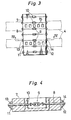
- Fig. 3 is a plan view of prestressed concrete floor board 7 in accordance with this invention
- Fig. 4 is a cross section taken along the line IV-IV in Fig. 3.
- pc steel wires 8 are buried, being extended in the widthwise direction (the transverse direction in Fig. 3), through turnbuckles 9.
- slots 10 are formed, being opened upward and enclosing these turnbuckles 9.
- the internal compressive stress of the concrete floor boards 7 is released by operating the turnbuckles in the slots 10 from outside.
- couplers of which threads are formed inside along the axial direction may be used.
- the pc steel wires 8 may not be necessarily linked by way of turnbuckles 9 or couplers, and in such a case, the internal compressive force may be released by cutting the pc steel wires 8 in the slots 10.
- slots 15 are provided to be filled with high strength mortar or the like in order to make the steel beams 4 and the concrete floor boards 7 integral.
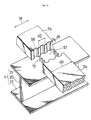
- Such concrete floor boards 7 are prefabricated at shop etc. in the following procedure. As shown in Fig. 5, a form 16a is set as indicated by an imaginary line, and a form 16b for slots 10,15 may be set if necessary.
- this form 16a unbonded pc steel wires 8 which do not adhere to concrete are arranged together with necessary reinforcing bars, and concrete is poured in. After curing for a specified period, a proper tension is applied to the pc steel wires 8 by means of a jack or the like to fix by means of support pressure boards 11 and 12, and fixing members 13 and 14. At this time, a compressive force acts on the concrete with the help of the support pressure boards 11 and 12, and a compressive stress is generated inside.
- concrete floor boards 7 in which a compressive stress is already present can be fabricated.
- Fig. 6 is a simplified perspective view showing part of the state of a concrete floor board 7 mounted on the steel beam 4 and Fig. 7 is a front view seen from the arrow A side of Fig. 6.
- the steel beam 4 extending in the horizontal direction comprises a web 20 extending in the vertical direction, and upper flange 21 and lower flange 22 extending in a direction perpendicular to the web 20 at both ends of the web 20.
- An antiskid member 23 for preventing the concrete floor board 7 from slipping is attached to the upper surface of the upper flange 21.
- This antiskid member 23 is, for example, a dowel which is composed of a plurality of bar- shaped projections 24 welded on the upper surface of the upper flange 21.
- a plurality of antiskid members 23 are disposed on the upper surface of the upper flange 21 at intervals.
- a plurality of concrete floor boards 7 are so placed, side by side, that the pc steel wires 8 and main beam 4 may be parallel to each other.
- protrusions 24 of the antiskid members 23 are inserted into the slots preliminarily provided at predetermined positions of the stopping part 7a called the hunch projecting downward of the concrete floor boards 7, and then the slots 15 are filled up with high strength mortar to fix the concrete floor boards 7 and the main beam 7 rigidly and integrally.
- the composite beam in accordance with the invention has smaller positive bending moment by this negative bending moment than the ordinary composite beam composed of unprestressed concrete floor boards disposed on the main beam.
- Fig. 8 is a plan view of the prestressed concrete floor board 7 of another embodiment, and Fig. 9 a cross section taken along the line IX-IX of Fig. 8.
- like numerals are attached to the parts corresponding to those used in the embodiment shown in Fig. 3.
- turnbuckles 9 are not used. Therefore, slots 10 in the embodiment in Fig. 3 are not formed either.
- the fixing members 13 and 14 of the pc steel wires 8 are loosened by jack operation or the like. Additionally, slots 15 are provided for the purpose of accomplishing the same effect as in the embodiment disclosed in Fig. 3.
- Fig. 10 explains the intensity of stress acting on the steel beam 4 and concrete floor boards 7 when the concrete floor boards shown in Fig. 3 and Fig. 8 are installed in the steel beam 4, while Fig. 11 shows the bending moment diagrams corresponding to Fig. 10.
- Fig. 10 for the convenience of simplified explanation, it is assumed that the steel beam 4 is supported by simple fulcrums 26 and 27 at both ends thereof.
- the state of the steel beam 4 being supported by fulcrums 26 and 27 is illustrated in diagram (1) of Fig. 10. In this state, the steel beam 4 is subjected to a positive bending moment 11 expressed by a parabola in a diagram (1) of Fig. 11 due to the equally distributed load by own weight.
- the actual bending moment is smaller than the bending moment of an ordinary composite beam expressed by an imaginary line 15 by the bending moment 13 due to prestress.
- the positive bending moment may be decreased in this invention, so that the section of steel beam 4 may be made smaller.
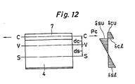
- Fig. 12 is a diagram presenting a foundation for analyzing practically the intensity of stress acting on the concrete floor boards 7 and steel beam 4 after releasing of prestress.
- Sectional forces acting on the composite section that is, the stress in the axial direction N and the bending moment M are expressed in Eqs. 1 and 2.
- pc represents prestress
- dc represents the distance between center of gravity c of the section of concrete floor board and the center of gravity v if composite section.
- edge stresses 6su and 6sl of the steel beam 4 are expressed in Eq. 3.
- Av is the section area of composite section
- Iv is the second moment of area of the composite section
- yvsu is the distance between the center of gravity of composite section and upper flange
- yvsl is the distance between the center of gravity of composite section and lower flange.
- yvcu is the distance between the center of gravity v of composite section and the upper surface of concrete floor board 7
- yvcl is the distance between the center of gravity v of composite section and the upper flange.
- the load to be considered in ordinary composite beams is 0.700 t/m 2 to 1.050 t/m2, while the load to be considered in this invention without using forms is 0.600 t/m 2 to 0.950 t/m 2 . Therefore, the dead load during installation of floor boards may be reduced by 14 to 10%.
- the inventor calculated the design relating to the ordinary composite beams and the composite beams according to this invention, and obtained the results are partly shown in TABLE 2. In this table, the allowable stress is assumed to be ⁇ 2100 kg/cm 2 , and the concrete section, 2736 cm by 230 cm.
- the weight ratio of main beam may be expressed as shown in Eq. 7. That is, in accordance with the invention, the weight of the main beam may be reduced by 12.0% from that of the conventional beam.
- the steel beam of composite beam bridge is subjected to the positive bending moment due to vertical loads of dead load and live loads of own weight of steel beam, floor board, soil covering, balustrade, pavement, etc., and a compressive stress acts on the upper edge side and a tensile stress is present on the lower edge side.
- a tensile force and a negative bending moment act on the steel beam part by releasing stress from the concrete floor boards after integrally forming precast prestressed concrete floor boards having an internal compressive stress and the steel beams, both the compressive stress on the upper edge side and the tensile stress on the lower edge side are reduced as compared with those in the conventional method.
- the method in accordance with the invention enables the composite beam bridge to resist a greater load than that in accordance with the conventional method. That is, when the two are compared in the case of same vertical load being applied to them, the required sectional area of the steel beam in this method is smaller, thereby reducing the steel beam in size and weight. Furthermore, by decreasing the sectional area of steel beam, the beam height can be lowered, so that the load of wind pressure or other factors applied on the side of the bridge may be decreased. Besides, this may be applied in a location where the space beneath the beam is limited, and by diminishing the height of the road erection, it is also economically advantageous.
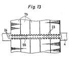
- Fig. 13 is a plan view of the concrete floor board by yet another embodiment
- Fig. 14 is a perspective view magnifying part of Fig. 13.
- Concrete floor boards 7b have undulated surfaces 55 formed at its both ends in the transverse direction (the direction parallel with the bridge axial direction). In each of the undulated surfaces 55, a plurality of concave portions 56 are formed at specified intervals along the bridge axial direction W. If, for example, the width d3 of this concrete floor board 7b is taken as 1.5 m, the depth d1 of the concave portion 56 is 2 cm, and the pitch d2 is 20 cm.
- the shape of the undulated surface 55 is 1.5 m, the depth d1 of the concave portion 56 is 2 cm, and the pitch d2 is 20 cm.
- the shape of the undulated surface 55 is not limited to that shown in Fig. 17, and as a matter of coarse, the depth d1 and d2 are not either limited.
- the concrete floor boards 7b in such shape are disposed, at specified intervals in confronting relation to each other, on the upper flange 10 of the steel beam 4. Thereafter, same as in the preceding embodiment, prestress is introduced, and the boards are fixed by the fixing members 52 after the generation of compressive stress.
- the foundation members and auxiliary members may be members composed of compound bodies of concrete and steel.
Claims (2)
Applications Claiming Priority (4)
| Application Number | Priority Date | Filing Date | Title |
|---|---|---|---|
| JP20959983A JPS60102405A (ja) | 1983-11-07 | 1983-11-07 | プレストレストコンクリ−ト部材を用いた合成構造部材形成工法 |
| JP209599/83 | 1983-11-07 | ||
| JP70503/84 | 1984-04-09 | ||
| JP7050384A JPS60212506A (ja) | 1984-04-09 | 1984-04-09 | 応力調整を伴なう合成構造部材形成工法 |
Related Child Applications (2)
| Application Number | Title | Priority Date | Filing Date |
|---|---|---|---|
| EP19890202096 Division EP0350139A3 (fr) | 1983-11-07 | 1984-11-07 | Procédé de fabrication d'un élément de construction composé |
| EP89202096.7 Division-Into | 1984-11-07 |
Publications (3)
| Publication Number | Publication Date |
|---|---|
| EP0141478A2 EP0141478A2 (fr) | 1985-05-15 |
| EP0141478A3 EP0141478A3 (en) | 1987-01-14 |
| EP0141478B1 true EP0141478B1 (fr) | 1990-10-17 |
Family
ID=26411659
Family Applications (2)
| Application Number | Title | Priority Date | Filing Date |
|---|---|---|---|
| EP84201618A Expired - Lifetime EP0141478B1 (fr) | 1983-11-07 | 1984-11-07 | Procédé de fabrication d'un élément de construction composé |
| EP19890202096 Ceased EP0350139A3 (fr) | 1983-11-07 | 1984-11-07 | Procédé de fabrication d'un élément de construction composé |
Family Applications After (1)
| Application Number | Title | Priority Date | Filing Date |
|---|---|---|---|
| EP19890202096 Ceased EP0350139A3 (fr) | 1983-11-07 | 1984-11-07 | Procédé de fabrication d'un élément de construction composé |
Country Status (3)
| Country | Link |
|---|---|
| US (1) | US4710994A (fr) |
| EP (2) | EP0141478B1 (fr) |
| DE (1) | DE3483413D1 (fr) |
Families Citing this family (34)
| Publication number | Priority date | Publication date | Assignee | Title |
|---|---|---|---|---|
| FR2627526A1 (fr) * | 1988-02-19 | 1989-08-25 | Roret Jean | Procede de fabrication d'une structure mixte beton-metal et structure ainsi obtenue |
| FR2698111B1 (fr) * | 1992-11-18 | 1995-02-03 | Razel Freres Entr | Procédé de construction d'un tablier de pont comportant une dalle en béton supportée par des poutres métalliques longitudinales. |
| US5577284A (en) * | 1994-02-22 | 1996-11-26 | Muller; Jean | Channel bridge |
| US5457840A (en) * | 1994-05-24 | 1995-10-17 | Derechin; Joshua | Fatigue resistant shear connector |
| US6345403B1 (en) * | 1995-05-08 | 2002-02-12 | Schuylkill Products, Inc. | Method of bridge construction using concrete diaphragms |
| US5617599A (en) * | 1995-05-19 | 1997-04-08 | Fomico International | Bridge deck panel installation system and method |
| US5802652A (en) * | 1995-05-19 | 1998-09-08 | Fomico International | Bridge deck panel installation system and method |
| WO1997018356A1 (fr) * | 1995-11-13 | 1997-05-22 | Reynolds Metals Company | Systeme de tablier de pont modulaire comprenant des elements creux extrudes en aluminium solidement fixes aux poutres de soutien |
| US6055693A (en) * | 1995-12-28 | 2000-05-02 | Owen Industries, Inc. | Railway short span trestle bridge |
| US6058666A (en) * | 1997-08-31 | 2000-05-09 | Lin; Wei-Hwang | Twin-axis prestressed single-tee beam with lower flange and process of construction |
| IL123543A (en) * | 1998-03-04 | 1999-12-31 | Meiranz Benjamin | Composite bridge superstructure with precast deck elements |
| KR100380637B1 (ko) * | 1999-05-10 | 2003-04-16 | 주식회사 인터컨스텍 | 교량의 내하력이 조정되는 프리스트레스트 콘크리트 거더및 이를 이용한 교량의 내하력 조정방법 |
| AU754130B1 (en) * | 2001-06-05 | 2002-11-07 | Bonacci Beam Pty Ltd | Building structural element |
| US6785925B1 (en) * | 2002-04-15 | 2004-09-07 | Curtis L. Donaldson | Bridge system |
| WO2004059089A1 (fr) * | 2002-12-30 | 2004-07-15 | Koo, Min Se | Poutre mixte precontrainte, structure de poutre mixte precontrainte en continu et procedes de fabrication et de raccordement correspondants |
| US7475446B1 (en) * | 2004-10-16 | 2009-01-13 | Yidong He | Bridge system using prefabricated deck units with external tensioned structural elements |
| US8020235B2 (en) * | 2008-09-16 | 2011-09-20 | Lawrence Technological University | Concrete bridge |
| US7814724B2 (en) * | 2007-10-09 | 2010-10-19 | Hntb Holdings Ltd. | Method for building over an opening via incremental launching |
| FR2933718B1 (fr) * | 2008-07-08 | 2011-12-02 | Razel | Procede pour realiser un pont, notamment un pont mixte et systeme de coffrage adapte a la mise en oeuvre d'un tel procede |
| US8069519B2 (en) | 2008-12-10 | 2011-12-06 | Bumen James H | Bridge decking panel with fastening systems and method for casting the decking panel |
| US8234738B2 (en) * | 2010-03-15 | 2012-08-07 | Newton Bridge Solutions Ltd | Bridge construction and method of replacing bridges |
| GB2512559B (en) * | 2010-07-05 | 2016-02-24 | Tb Composites Ltd | Bridge superstructure decking panel and attachment system |
| WO2012044097A2 (fr) * | 2010-09-30 | 2012-04-05 | 주식회사 아앤시티 | Structure de dalle de plancher pour pont |
| CN102561194B (zh) * | 2011-12-30 | 2016-05-04 | 邵旭东 | 安全型智能钢绞线二次张拉系统 |
| US9309634B2 (en) | 2012-04-06 | 2016-04-12 | Lawrence Technological University | Continuous CFRP decked bulb T beam bridges for accelerated bridge construction |
| CN103790237B (zh) * | 2014-02-17 | 2016-07-06 | 沈阳建筑大学 | 一种预制混凝土叠合楼板与h型钢梁的连接构件 |
| US10895047B2 (en) | 2016-11-16 | 2021-01-19 | Valmont Industries, Inc. | Prefabricated, prestressed bridge module |
| US10407838B1 (en) * | 2017-02-06 | 2019-09-10 | Integrated Roadways, Llc | Modular pavement slab |
| CN107476180B (zh) * | 2017-08-09 | 2019-09-10 | 重庆交通大学 | 释放桥道板拉应力的钢-砼组合连续梁桥 |
| US11041278B2 (en) * | 2019-10-30 | 2021-06-22 | Dutchland, Inc. | Connection assembly |
| SE2000043A1 (en) * | 2020-02-27 | 2021-08-28 | Filippo Sangiorgio | Self-locking filigree slab |
| CN113073557B (zh) * | 2021-03-19 | 2022-08-30 | 中铁大桥局集团第一工程有限公司 | 一种钢混结合连续钢桁梁桥混凝土桥面板的安装方法 |
| US11718964B2 (en) * | 2021-09-13 | 2023-08-08 | Summit Precast Concrete, Lp | Bridge apparatus, systems and methods of construction |
| CN114961313A (zh) * | 2022-04-11 | 2022-08-30 | 中建国际建设有限公司 | 一种后张预应力楼板锚固端修补方法 |
Family Cites Families (11)
| Publication number | Priority date | Publication date | Assignee | Title |
|---|---|---|---|---|
| US1818254A (en) * | 1927-09-10 | 1931-08-11 | William S Hewett | Method and means for tying concrete |
| US2315895A (en) * | 1941-09-11 | 1943-04-06 | John M Crom | Concrete construction |
| US2590685A (en) * | 1947-02-06 | 1952-03-25 | Coff Leo | Prestressed concrete structure |
| DE971109C (de) * | 1949-06-15 | 1958-12-11 | Demag Ag | Verfahren zum Herstellen von Stahltraegern in Verbund mit einer vorgespannten Stahlbetonplatte, insbesondere fuer Balkenbruecken, Haengebruecken und Stabbogenbruecken |
| DE956685C (de) * | 1953-03-07 | 1957-01-24 | Aug Kloenne Fa | Beton- oder Stahlbetonfertigteil fuer Verbundkonstruktionen |
| US3427772A (en) * | 1966-09-06 | 1969-02-18 | George W Williams | Apparatus for post-tensioning and interconnecting re-enforcing wires using key hole anchor plates in a concrete structure |
| DE2202610A1 (de) * | 1972-01-20 | 1973-07-26 | Hans Muess | Verbundtraeger in fertigteilbauweise |
| DE2519225A1 (de) * | 1975-04-30 | 1976-11-18 | Paul E Loewrigkeit | Belagstein |
| US4125580A (en) * | 1977-05-02 | 1978-11-14 | Dyckerhoff & Widmann Aktiengesellschaft | Process for the manufacture of pretensioned carriageway slabs |
| US4343123A (en) * | 1979-07-16 | 1982-08-10 | Roosseno Soerjohadikusumo | Composite bridge with precompression system |
| US4282619A (en) * | 1979-11-16 | 1981-08-11 | Havens Steel Company | Truss structure |
-
1984
- 1984-11-07 EP EP84201618A patent/EP0141478B1/fr not_active Expired - Lifetime
- 1984-11-07 EP EP19890202096 patent/EP0350139A3/fr not_active Ceased
- 1984-11-07 DE DE8484201618T patent/DE3483413D1/de not_active Expired - Fee Related
-
1986
- 1986-10-06 US US06/915,900 patent/US4710994A/en not_active Expired - Fee Related
Also Published As
| Publication number | Publication date |
|---|---|
| US4710994A (en) | 1987-12-08 |
| EP0141478A3 (en) | 1987-01-14 |
| EP0350139A3 (fr) | 1990-10-17 |
| EP0350139A2 (fr) | 1990-01-10 |
| EP0141478A2 (fr) | 1985-05-15 |
| DE3483413D1 (de) | 1990-11-22 |
Similar Documents
| Publication | Publication Date | Title |
|---|---|---|
| EP0141478B1 (fr) | Procédé de fabrication d'un élément de construction composé | |
| KR100536489B1 (ko) | 프리스트레스트 강합성보의 제작 방법 및 이에 의하여제작된 강합성보 | |
| EP0996795B1 (fr) | Colonne composite en acier/beton | |
| US5457839A (en) | Bridge deck system | |
| KR100522170B1 (ko) | 단경간 및 다경간 합성형교(合成桁橋)의 시공법 | |
| CA1179519A (fr) | Element de construction prefabrique et methode de production | |
| KR101693256B1 (ko) | 조립식 psc 교량의 시공방법 | |
| CA2023198C (fr) | Poutrelle en materiau composite et methode de fabrication de ladite poutrelle | |
| KR101546951B1 (ko) | 프리캐스트 패널과 강박스 거더를 이용한 연속교의 시공 방법 | |
| KR101326170B1 (ko) | 연결부 정착단을 구비한 피에스씨 거더 세그먼트, 이를 이용한 피에스씨 거더 및 모듈러 피에스씨 거더교 시공방법 | |
| DE112004000197T5 (de) | Decking-Kontruktionssystem | |
| US20040107660A1 (en) | Composite floor system | |
| CN111424869A (zh) | 混凝土楼板次梁组合预制构件和制作方法 | |
| KR100565384B1 (ko) | 빔 연결부재와 강재가로보를 이용한 프리캐스트 피에스씨빔의 연속화 구조 및 이를 이용한 교량시공방법 | |
| US4742591A (en) | Cable stayed bridge having box edge beams and method of construction | |
| JPH0475322B2 (fr) | ||
| KR101324982B1 (ko) | 연결부 정착단을 구비한 피에스씨 거더를 이용한 보도교 시공방법 | |
| KR102325276B1 (ko) | 하프 pc 연속슬래브 및 이의 시공 방법 | |
| KR101752285B1 (ko) | 광폭 psc 하부플랜지와 단면확대용 상부플랜지를 갖는 하이브리드 보 및 이를 이용한 구조물 | |
| CN116601364A (zh) | 混凝土结构联接器 | |
| CA2441737C (fr) | Plancher composite | |
| KR20180070097A (ko) | 시공단계에서 연속화 공법이 가능한 프리스트레스트 하이브리드 와이드 플랜지 보 구조시스템 | |
| JPH0320524B2 (fr) | ||
| KR100995114B1 (ko) | 바닥판을 이용한 휨 저항 구조부재의 인장-프리스트레스도입 방법 | |
| CA2288867C (fr) | Colonne composite en acier/beton |
Legal Events
| Date | Code | Title | Description |
|---|---|---|---|
| PUAI | Public reference made under article 153(3) epc to a published international application that has entered the european phase |
Free format text: ORIGINAL CODE: 0009012 |
|
| AK | Designated contracting states |
Designated state(s): BE DE FR GB |
|
| PUAL | Search report despatched |
Free format text: ORIGINAL CODE: 0009013 |
|
| AK | Designated contracting states |
Kind code of ref document: A3 Designated state(s): BE DE FR GB |
|
| 17P | Request for examination filed |
Effective date: 19870710 |
|
| 17Q | First examination report despatched |
Effective date: 19880502 |
|
| GRAA | (expected) grant |
Free format text: ORIGINAL CODE: 0009210 |
|
| AK | Designated contracting states |
Kind code of ref document: B1 Designated state(s): BE DE FR GB |
|
| XX | Miscellaneous (additional remarks) |
Free format text: TEILANMELDUNG 89202096.7 EINGEREICHT AM 07/11/84. |
|
| REF | Corresponds to: |
Ref document number: 3483413 Country of ref document: DE Date of ref document: 19901122 |
|
| ET | Fr: translation filed | ||
| BERE | Be: lapsed |
Owner name: HARUMOTO IRON WORKS CO. LTD Effective date: 19901130 |
|
| PLBE | No opposition filed within time limit |
Free format text: ORIGINAL CODE: 0009261 |
|
| STAA | Information on the status of an ep patent application or granted ep patent |
Free format text: STATUS: NO OPPOSITION FILED WITHIN TIME LIMIT |
|
| 26N | No opposition filed | ||
| PGFP | Annual fee paid to national office [announced via postgrant information from national office to epo] |
Ref country code: GB Payment date: 19911025 Year of fee payment: 8 |
|
| PGFP | Annual fee paid to national office [announced via postgrant information from national office to epo] |
Ref country code: FR Payment date: 19911107 Year of fee payment: 8 |
|
| PGFP | Annual fee paid to national office [announced via postgrant information from national office to epo] |
Ref country code: DE Payment date: 19911129 Year of fee payment: 8 |
|
| PGFP | Annual fee paid to national office [announced via postgrant information from national office to epo] |
Ref country code: BE Payment date: 19920504 Year of fee payment: 8 |
|
| PG25 | Lapsed in a contracting state [announced via postgrant information from national office to epo] |
Ref country code: GB Effective date: 19921107 |
|
| PG25 | Lapsed in a contracting state [announced via postgrant information from national office to epo] |
Ref country code: BE Effective date: 19921130 |
|
| BERE | Be: lapsed |
Owner name: HARUMOTO IRON WORKS CO. LTD Effective date: 19921130 |
|
| GBPC | Gb: european patent ceased through non-payment of renewal fee |
Effective date: 19921107 |
|
| PG25 | Lapsed in a contracting state [announced via postgrant information from national office to epo] |
Ref country code: FR Effective date: 19930730 |
|
| PG25 | Lapsed in a contracting state [announced via postgrant information from national office to epo] |
Ref country code: DE Effective date: 19930803 |
|
| REG | Reference to a national code |
Ref country code: FR Ref legal event code: ST |