EP0141218B1 - Detector for indicating receiving disturbances in fm broadcast reception - Google Patents
Detector for indicating receiving disturbances in fm broadcast reception Download PDFInfo
- Publication number
- EP0141218B1 EP0141218B1 EP84111154A EP84111154A EP0141218B1 EP 0141218 B1 EP0141218 B1 EP 0141218B1 EP 84111154 A EP84111154 A EP 84111154A EP 84111154 A EP84111154 A EP 84111154A EP 0141218 B1 EP0141218 B1 EP 0141218B1
- Authority
- EP
- European Patent Office
- Prior art keywords
- detector
- level
- circuit
- signal
- disturbance
- Prior art date
- Legal status (The legal status is an assumption and is not a legal conclusion. Google has not performed a legal analysis and makes no representation as to the accuracy of the status listed.)
- Expired
Links
Images


Classifications
-
- H—ELECTRICITY
- H04—ELECTRIC COMMUNICATION TECHNIQUE
- H04B—TRANSMISSION
- H04B1/00—Details of transmission systems, not covered by a single one of groups H04B3/00 - H04B13/00; Details of transmission systems not characterised by the medium used for transmission
- H04B1/06—Receivers
- H04B1/10—Means associated with receiver for limiting or suppressing noise or interference
- H04B1/1027—Means associated with receiver for limiting or suppressing noise or interference assessing signal quality or detecting noise/interference for the received signal
Definitions
- the invention relates to a detector for displaying reception interference in FM radio reception of the type referred to in the preamble of claim 1.
- Such a detector is known from DE-B-1 282 746. Such detectors are preferably used to improve radio reception in motor vehicles. The detector has the task of recognizing and displaying a reception fault. A switchover measure is then initiated, which is generally carried out electronically.
- the published patent application DE-A-1 122 057 presents a tuner control with a detector for perceiving the signal level in a radio receiver.
- US Pat. No. 3,825,697 refers to a switchover device which switches from stereo operation to mono operation after detection of a fault as a result of the multipath reception. In all of the cases described, a detector is required to detect the fault.
- the arrangement known from DE-B-1 282 746 also detects interference amplitude modulation; in addition, this arrangement also has a detector for indicating before frequency interference.
- the output signals of the detector for interference amplitude modulation and the detector for frequency interference hub are combined in such a way that for low UHF signal voltage values the interference amplitude modulation is decisive for the display of a reception interference, while for relatively high signal voltage values the frequency interference hub determines the display of a reception interference.
- EP-A-0 010 552 in which interference amplitude modulation and frequency deviation are detected.
- the output signals of the two detectors are used to form the quotient 8 A / Ao ⁇ , which is a measure of the degree of multipath interference.
- the object of the invention is to quickly and accurately identify and indicate the presence of reception interference which occurs in the case of FM stereo or mono reception and in particular results from multi-path reception with large differences in transit time of the superimposed waves.
- a disadvantageous basic idea of the present invention resides in the combination of the output signals of a detector for displaying frequency interference and an AM detector for displaying interference amplitude modulation. All previously known detectors for displaying reception interference are limited to evaluating the interference-related amplitude modulation of the frequency-modulated high-frequency carrier. This creates the false indications of reception disorders described above. In systems based on switching between different antennas, this leads to additional reception interference and to long switching times.
- the RF signal resulting from the superposition of the waves superimposed on Rayleigh does not lead to a distortion in the demodulated signal if the noise level of the receiving system is not fallen below during the drop in amplitude.
- the amplitude modulation shown in FIG. 12 becomes ineffective due to the amplitude limitation before the frequency demodulation. If the transit time difference of the worlds superimposed in the wave field exceeds a certain value, then depending on the frequency useful stroke and on the amplitude ratios of the superimposed waves, an interference frequency deviation occurs, which leads to frequency interference peaks 26, which are shown by curve 27 in FIG. 11. When comparing FIGS. 11 and 12 it can be seen that at times when frequency interference peaks occur in the distorted signal, an amplitude dip occurs in the curve below.
- This correlation is used by the present invention in order to determine reception disturbances particularly quickly and reliably. From the time course of the amplitude modulation, the occurrence of reception interference cannot be concluded with certainty. This is particularly true in the moving vehicle, where the resulting amplitude modulation depends on the one hand on the movement within a wave field with partial waves with small transit time differences, and on the system-related interference as a result of the superposition of several waves with large transit time differences. With the help of the simultaneous evaluation of frequency interference peaks and the amplitude modulation according to the invention, the display of the reception interference detector is fast and reliable enough to initiate switchover measures sufficiently early in the event of a disturbance.
- both the amplitude of the high-frequency carrier and the instantaneous fraud of the resulting received high-frequency oscillation are falsified at the moment of the interference.
- a disturbance can therefore be reliably recognized by the simultaneous occurrence of amplitude and frequency disturbances.
- a longer observation time of the fault is not necessary for its accurate detection.
- a suitable switchover measure to avoid these receiving errors in the receiving system.
- the detection times for reception disturbances which can be realized with the detector according to the invention for displaying reception disturbances can be reduced to the range of ⁇ s. Switching measures can be derived from this, which, if suitably designed, ensure that audible reception interference is avoided.
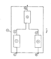
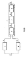
- the 1 shows a detector for displaying reception interference. This consists of a detector 1 for displaying frequency interference, an AM detector 10 for displaying interference amplitude modulation and an evaluation circuit 2 which has two inputs.
- the possibly disturbed signal on the high-frequency or intermediate-frequency carrier 21 is fed to both detectors 1 and 10.
- the two output signals 31 and 33 of these detectors are each fed to the evaluation circuit 2 via an input.
- the evaluation circuit 2 is designed in such a way that the output signal 24 depends both on the interference amplitude modulation of the high-frequency carrier 21 and on its frequency interference swing.
- the evaluation circuit 2 is designed in such a way that the output signal 24 has a binary character and is designed in such a way that the occurrence of a disturbance is only indicated if both the frequency disturbance stroke and the disturbance amplitude modulation of the received high-frequency or intermediate-frequency signal 21 each exceed a certain threshold.
- the binary decision for the presence of a reception fault is made by a logic circuit 4.
- the occurrence of the interference amplitude modulation or the frequency interference stroke is determined. These two pieces of information are linked in logic circuit 4.
- a suitable setting of the threshold values is expediently measured at the audibility threshold of the received disturbances.
- the AM detector 10 is designed as an envelope curve demodulator for displaying interference amplitude modulation. It is advisable to choose a frequency bandwidth of the AM detector that is not smaller than the FM channel bandwidth.
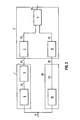
- FIG. 2 shows an advantageous embodiment of the evaluation circuit 2.
- This has a unipolar or bipolar level discriminator 3, to which the output signal 31 of the detector 1 is fed to indicate frequency interference.
- a unipolar level discriminator 11, to which the output signal 33 of the AM detector 10 is fed, is present in the signal branch for determining interference amplitude modulation.
- the output signals 23 and 41 of the two level discriminators 3 and 11 are evaluated by the logic circuit 4 in such a way that the output signal 24 of the evaluation circuit 2 indicates in binary fashion the occurrence of a reception disturbance.
- the output signal 24 only indicates a fault if both thresholds of the level discriminators 3 and 11 are exceeded.
- Reception interference occurs in the output voltages 31 and 33 of the two detectors 1 and 10 in pulse form.
- these pulses are worked out of the rest of the signal with the aid of a circuit which increases the slope of the pulse edges. This leads to a further improvement in the accuracy of the detection of reception problems.
- filters with a high-pass character are provided in the present invention, which do not force a long detection time of the interference by delaying action.
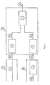
- FIG. 3 shows for the FM detector 1 a circuit 5 which increases the slope of the pulse edges and which is connected downstream of the FM demodulator 8.
- the interference-related pulse peaks in the output signal 31 are accordingly larger than the corresponding peaks in the signal 22, the output signal of the FM demodulator 8, and can be more easily separated from the rest of the useful signal by the level discriminator 3.
- a circuit 5 which increases the slope of the pulse edges can be connected downstream of the AM demodulator 18 in a manner similar to that in the branch for detecting frequency interference.
- the interference pulses in the output signal 33 are more strongly emphasized here than the amplitude curve, which results from the movement of the vehicle in standing waves in the reception field, than in signal 40, the output signal of the AM demodulator 18. This is shown in FIG. 4
- FIG. 5 shows a combination of the measures according to FIGS. 4 and 3.
- a circuit 5 which increases the slope of the pulse edges can be produced in a particularly simple embodiment by an RC high-pass element.
- the time constant of this RC circuit can be set by selecting the series capacitance and the parallel resistance. This time constant is advantageously set so that the usual occurring reception interference, the best possible detection of the interference pulses is made possible.
- Such a differentiating element shown in FIG. 6 can be realized in a further embodiment of the invention as an RC chain circuit, as shown in FIG. 7. The steepness of the pulse edges increases with the number of chain links.
- a unipolar level discriminator 7 and 11 are used both in the branch for determining frequency interference peaks and in the branch for determining interference amplitude modulation.
- a two-way rectifier 9 with the output signal 29 is connected upstream of the unipolar level discriminator 7. Without this two-way rectifier, only interference pulses of one polarity in signal 31 would be evaluated. By additional evaluation of the interference pulses of the other polarity, the security for the detection of the interference can be further increased in a short time.
- the slope of the pulse edge raising circuit 5 is realized by a frequency-dependent network with a high-pass character.
- a circuit can be designed to be frequency-independent.
- a circuit is selected which, in a manner known per se, consists of a power function with even-numbered exponents or a sum of such power functions with the same sign with respect to the relationship between output and input signal, the smallest occurring exponent being greater than the number 1
- the full-wave rectifier 9 can be omitted.
- Such a circuit which increases the slope of the pulse edges, can be assembled in a particularly advantageous manner from semiconductor diode characteristics.
- a circuit is of particular importance, in the context of which there is a hyperbolic cosine function between the output signal and the input signal.
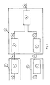
- the logic circuit 4 is designed as an AND gate.
- a unipolar or bipolar level discriminator 3 is used in FIG. 9.
- the output voltage 28 of this circuit 14 increases with the input signals 31 and 33. If the output voltage 28 exceeds the threshold value specified in the level discriminator 3, its output signal 23 results in a binary display for the occurrence of the reception interference.
- the downstream logic circuit 4 could be used for further logical processing of the signal 23.
- the other system components of the detector according to the invention are characterized in claims 17 to 24 with a circuit 14 for analog connection of the output signals 31 and 33.
- the level threshold of the level discriminator or the level discriminators is set dynamically depending on the time-averaged frequency swing.
- This time-averaged frequency deviation can be done in a manner known per se, for. B. derived from the signal 22 at the output of the FM demodulator 8.
- the level threshold is raised accordingly with increasing peaks of the useful frequency swing.
- a detector according to the present invention will also indicate the noise as a disturbance in the event of an unfavorable signal-to-noise ratio in the high-frequency channel.
- the level threshold is additionally set depending on the signal-to-noise ratio.
- This setting is designed according to the invention in such a way that in the presence of pure noise a reception disturbance is still displayed, so that switchover measures can be carried out with the aid of this detection even when there is no signal.
- the signal-to-noise ratio becomes smaller, only the sensitivity of the interference detection is reduced. Since the receiver noise often determines the total noise in the system, the level threshold can be set in a particularly simple embodiment of the invention on the basis of the time-averaged amplitude of the high-frequency carrier.
- the level threshold of the level discriminator 7 or the Level discriminators 3 and 11 may be set to be suitable only or additionally depending on the time-averaged carrier amplitude.
- the level threshold or level thresholds are expediently raised as the carrier amplitude decreases.
- a circuit for determining the peak values of the frequency useful travel can be present and the threshold of the level discriminator 7 or the level discriminators 3 and 11 can be set exclusively or additionally as a function of these peak values of the frequency useful travel. It is expedient if the level threshold or the level thresholds are raised with increasing peak values of the frequency useful stroke.
Description
Die Erfindung betrifft einen Detektor zur Anzeige von Empfangsstörungen beim UKW-Rundfunkempfang der im Oberbegriff des Anspruchs 1 bezeichneten Art.The invention relates to a detector for displaying reception interference in FM radio reception of the type referred to in the preamble of
Ein solcher Detektor ist aus DE-B-1 282 746 bekannt. Solche Detektoren werden Vorzugsweise verwendet zur Verbesserung des Rundfunkempfangs in Kraftfahrzeugen. Der Detektor hat die Aufgabe, eine Empfangsstorung zu erkennen und anzuzeigen. Daraufhin wird eine Umschaltmaßnahme eingeleitet, die im allgemeinen elektronisch durchgeführt wird. Zum Beispiel wird in der Offenlegungsschrift DE-A1-3 107 970 ein FM-Empfanger (FM = Frequenzmodulation) beschrieben, in dem mit Hilfe eines Detektors und einer Umschalteinrichtung automatisch das Mehrwegerauschen vermieden wird. In der Offenlegungsschrift DE-A- 1 122 057 wird eine Tunersteuerung mit einem Detektor zum Wahrnehmen des Signalpegels in einem Rundfunkempfänger vorgestellt. Weiterhin ist in der US-Patentschrift 3 825 697 von einer Umschalteinrichtung die Rede, die nach Erkennung einer Störung infolge des Mehrwegeempfangs von Stereobetrieb auf Monobetrieb umschaltet. In allen beschriebenen Fällen ist ein Detektor zur Erkennung der Störung erforderlich.Such a detector is known from DE-B-1 282 746. Such detectors are preferably used to improve radio reception in motor vehicles. The detector has the task of recognizing and displaying a reception fault. A switchover measure is then initiated, which is generally carried out electronically. For example, the published patent application DE-A1-3 107 970 describes an FM receiver (FM = frequency modulation) in which the multipath noise is automatically avoided with the aid of a detector and a switching device. The published patent application DE-A-1 122 057 presents a tuner control with a detector for perceiving the signal level in a radio receiver. Furthermore, US Pat. No. 3,825,697 refers to a switchover device which switches from stereo operation to mono operation after detection of a fault as a result of the multipath reception. In all of the cases described, a detector is required to detect the fault.
Ein Detektor zur Erkennung von Störungen ist aus der US-Patentschrift 4 216 353 bekannt. Dieser Detektor ist speziell konzipiert für die Erkennung von störender Mehrwegeausbreitung der elektromagnetischen Wellen mit großen unterschiedlichen Laufzeiten. Aus diesem Effekt resultieren am Ausgang des Frequenzdemodulators ein erhöhtes Rauschen und eine Verzerrung der niederfrequenten Nachtricht. Im Fall der Stereo-Aussendung führt dieser Effekt auch zu einem erhöhten Übersprechen zwischen den beiden Stereo-Kanälen. Der in dieser Patentschrift beschriebene Detektor beruht auf der Auswertung des Amplituden/Zeitverlaufs des empfangsseitig vorliegenden frequenzmodulierten Signals. Dieser Detektor hat insbesondere im Hinblick auf einen Einsatz in einem Autoempfänger folgende Nachteile:
- Es ist bekannt, daß die Überlagerung von Teilwellen am Empfangsort bei Laufzeitunterschieden zwischen einer µs und 100 µs zu nennenswerten Verzerrungen der niederfrequenten Nachricht am Ausgang des FM-Demodulators führt. Diese Verzerrung geht einher mit einer vom niederfrequenten Nachrichteninhalt abhängigen Amplitudenmodulation des resultierenden Hochfrequenzträgers am Empfangsort. Der in der US-
Patentschrift 4 216 353 angegebene Detektor erkennt diese Amplitudenmodulation und zeigt sie als Störung an. Meistens jedoch ist das Wellenfeld aus Teilwellen zusammengesetzt, deren Laufzeitunterschiede unter einer Jls liegen. Diese Überlagerung der Teilwellen führt empfängerseitig nicht zu Störungen, verursacht aber eine starke Ortsabhängigkeit der resultierenden Feldamplitude. Der Eingangspegel des Autoempfängers erfährt deshalb durch die Eigenbewegung des Fahrzeugs in diesem Wellenfeld eine zeitliche Amplitudenänderung, die sich als Amplitudenmodulation ausdrückt. Der bekannte Detektor besitzt deshalb den Nachteil, zwischen einer Arnplitudenmodulationsart, die nicht zu Störungen führt, und einer anderen Amplitudenmodulationsart, die auf Grund der Mehrwegeausbreitung mit großen Laufzeitunterschieden entsteht und deshalb Störungen hervorruft, unterscheiden zu müssen. Besonders schwierig ist die Situation dadurch, daß beide Modulationsarten statistisch und zeitweise gleichzeitig auftreten. Daraus resultiert eine unsichere Erkennung der wirklichen Störung und eine verhältnismäßig große Detektionszeit. Diese Detektionszeit führt dazu, daß die Eingriffe in das Empfangssystem durch Umschalten erst so spät vorgenommen werden können, daß der Rundfunkhörer die Störung bereits wahrgenommen hat.
- It is known that the superposition of partial waves at the receiving location with delay differences between one µs and 100 µs leads to significant distortions of the low-frequency message at the output of the FM demodulator. This distortion is accompanied by an amplitude modulation of the resulting high-frequency carrier at the receiving location, which is dependent on the low-frequency message content. The detector disclosed in US Pat. No. 4,216,353 detects this amplitude modulation and indicates it as a disturbance. Most of the time, however, the wave field is composed of partial waves, the transit time differences of which are less than one Jl s. This superposition of the partial waves does not lead to interference on the receiver side, but causes the resulting field amplitude to be highly dependent on location. The input level of the car receiver therefore experiences a temporal change in amplitude due to the vehicle's own movement in this wave field, which is expressed as amplitude modulation. The known detector therefore has the disadvantage of having to distinguish between one type of amplitude modulation which does not lead to interference and another type of amplitude modulation which arises due to the multipath propagation with large differences in transit time and therefore causes interference. The situation is particularly difficult because both types of modulation occur statistically and temporarily at the same time. This results in an uncertain detection of the real disturbance and a relatively long detection time. This detection time means that the interventions in the receiving system can only be made by switching over so late that the radio listener has already noticed the interference.
Auch die aus DE-B-1 282 746 bekannte Anordnung erkennt Störamplitudenmodulation, daneben besitzt diese Anordnung auch einen Detektor zur Anzeige vor Frequenzstörhub. Die Ausgangssignale des Detektors für Störamplitudenmodulation und des Detektors für Frequenzstörhub werden auf eine Solche Weise kombiniert, daß für niedrige UHF Signalspannungswerte die Störamplitudenmodulation bestimmend ist für die Anzeige einen Empfangstörung, während für relativ hohe Signalspannungswerte der Frequenzstörhub die Anzeige einer Empfangsstörung bestimmt.The arrangement known from DE-B-1 282 746 also detects interference amplitude modulation; in addition, this arrangement also has a detector for indicating before frequency interference. The output signals of the detector for interference amplitude modulation and the detector for frequency interference hub are combined in such a way that for low UHF signal voltage values the interference amplitude modulation is decisive for the display of a reception interference, while for relatively high signal voltage values the frequency interference hub determines the display of a reception interference.
Weiter ist aus EP-A-0 010 552 eine Anordnung bekannt, bei der Störungamplitudenmodulation und Frequenzhub detektiert werden. Die Ausgangssignale der beiden Detektoren werden dabei zur Formung des Quotients 8 A/Ao δω, der ein Maß for den Grad der Mehrwegsempfangstörungen ist, benutz.Furthermore, an arrangement is known from EP-A-0 010 552 in which interference amplitude modulation and frequency deviation are detected. The output signals of the two detectors are used to form the quotient 8 A / Ao δω, which is a measure of the degree of multipath interference.
Aufgabe der Erfindung ist es, das Vorliegen von Empfangsstörungen, die beim UKW-Stereo-oder -Monoempfang auftreten und insbesondere vom Mehrwegeempfang mit starken Laufzeitunterschieden der überlagerten Wellen herrühren, schnell und treffsicher zu erkennen und anzuzeigen.The object of the invention is to quickly and accurately identify and indicate the presence of reception interference which occurs in the case of FM stereo or mono reception and in particular results from multi-path reception with large differences in transit time of the superimposed waves.
Diese Aufgabe wird durch die Merkmale des Kennzeichens des Anspruchs 1 gelöst.This object is achieved by the features of the characterizing part of
Weitere vorteilhafte Merkmale und vorteilhafte Ausführungsformen der Erfindung sind in den abhängigen Ansprüchen gekennzeichnet.Further advantageous features and advantageous embodiments of the invention are characterized in the dependent claims.
Die Erfindung, Ihre Merkmale und Vorteile sowie weitere Einzelheiten werden anhand von Ausführungsbeispeilen erläutert, die in der Zeichnung dargestellt sind. In dieser Beschreibung werden folgende Abkorzungen verwendet: FM = Frequenzmodulation, AM = Amplitudenmodulation, HF = Hochfrequenz. ZF = Zwischenfreguenz. In der Zeichnung zeigen:
- Fig. 1 ein Blockschaltbild der grundsätzlichen Ausführung des Detektors nach der Erfindung,
- Fig. 2 ein Blockschaltbild einer Ausführungsform der Auswerteschaltung des Detektors,
- Fig. 3 und 4 ein Blockschaltbild bzw. Teilblockschaltbild zweier abgewandelter Ausführungsformen des Detektors nach der Erfindung mit besonderen Ausführungen von FM-und AM-Detektor und der Auswerteschaltung nach Fig. 2,
- Fig. 5 ein Blockschaltbild einer Ausführungsform des Detektors als Kombination von Fig. 3 und 4,
- Fig. 6 und 7 je ein Schaltbild zweier Ausführungsformen der die Steilheit der Pulsflanken anhebenden Schaltung,
- Fig. 8 ein Teilblockschaltbild des Detektors nach der Erfindung mit einer weiteren Ausführungsform der Auswerteschaltung,
- Fig. 9 ein Blockschaltbild des Detektors mit einer Schaltung (14) zur analogen Verknüpfung der Ausgangssignale des Detektors zur Anzeige von Frequenzstörhub (1) und des AM-Detektors (10) zur Anzeige von Störamplitudenmodulation,
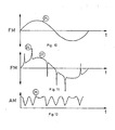
- Fig. 10 ein Diagramm des zeitlichen Verlaufs des Nutzfrequenzhubes bei sinusförmigem NF-Signal,
- Fig. 11 ein Diagramm des zeitlichen Verlaufs des resultierenden Frequenzhubes bei Überlagerung von Wellen mit großen Laufzeitunterschieden bei sinusförmigem Nutzsignal,
- Fig. 12 ein Diagramm des zeitlichen Verlaufs der resultierenden Empfangsträgeramplitude bei Mehrwegeausbreitung mit großen Laufzeitunterschieden oder beim Empfang im fahrenden Auto bei Mehrwegeausbreitung mit kleinen Laufzeitunterschiedenoder bei vermischten Effekten.
- 1 is a block diagram of the basic design of the detector according to the invention,
- 2 shows a block diagram of an embodiment of the evaluation circuit of the detector,
- 3 and 4 is a block diagram or partial block diagram of two modified embodiments of the detector according to the invention with special designs of FM and AM detector and the evaluation circuit according to FIG. 2,
- 5 is a block diagram of an embodiment of the detector as a combination of FIGS. 3 and 4,
- 6 and 7 are each a circuit diagram of two embodiments of the circuit increasing the slope of the pulse edges,
- 8 is a partial block diagram of the detector according to the invention with a further embodiment of the evaluation circuit,
- 9 is a block diagram of the detector with a circuit (14) for the analog connection of the output signals of the detector for displaying frequency interference (1) and the AM detector (10) for displaying interference amplitude modulation,
- 10 shows a diagram of the time profile of the useful frequency swing with a sinusoidal LF signal,
- 11 shows a diagram of the course over time of the resulting frequency swing when waves with large transit time differences are superimposed on a sinusoidal useful signal,
- Fig. 12 is a diagram of the temporal course of the resulting receiver carrier amplitude when multipath propagation with large transit time differences or when receiving in a moving car with multipath propagation with small transit time differences or with mixed effects.
Ein widtiger Grundgedanke der vorliegenden Erfindung beruht in der Verknüpfung der Ausgangssignale eines Detektors zur Anzeige von Frequenzstörhub und eines AM-Detektors zur Anzeige von Störamplitudenmodulation. Alle bisher bekannten Detektoren zur Anzeige von Empfangsstörungen sind darauf beschränkt, die störungsbedingte Amplitudenmodulation des frequenzmodulierten Hochfrequenzträgers auszuwerten. Dadurch entstehen die oben beschriebenen Fehlindikationen von Empfangsstörungen. Dies führt bei Systemen, die auf der Umschaltung zwischen verschiedenen Antennen beruhen, zu zusätzlichen Empfangsstörungen und zu lagen Umschaltzeiten.A disadvantageous basic idea of the present invention resides in the combination of the output signals of a detector for displaying frequency interference and an AM detector for displaying interference amplitude modulation. All previously known detectors for displaying reception interference are limited to evaluating the interference-related amplitude modulation of the frequency-modulated high-frequency carrier. This creates the false indications of reception disorders described above. In systems based on switching between different antennas, this leads to additional reception interference and to long switching times.
Die Mangelhaftigkeit der Erkennung von Empfangsstörungen aus dem zeitlichen Verlauf der Trägeramplitude nach den am Anmeldetag bekannten Verfahren, geht beispielhaft aus folgender Betrachtung der in Fig. 10 bis 12 dargestellten Signal-Zeitverläufe hervor. Ist das zu übertragende Signal 25 sinusförmig, so ist bei ungestörter Übertragung der zeitliche Verlauf 25 des Nutzfrequenzhubs ebenfalls sinusförmig, wie in Fig. 10 dargestellt. Bewegt sich die Antenne im Empfangswellenfeld, das sich aus einer Reihe von überlagerten, aus unterschiedlichen Richtungen infolge von Mehrwegeausbreitung einfallenden Wellen mit kleinen Laufzeitunterschieden zusammensetzt, so kann sich am Empfängereingang ein zeitlicher Verlauf der Trägeramplitude einstellen, wie er z. B. durch die Kurve 28 in Fig. 12 dargestellt ist. In diesem Fall führt das aus der Superposition der nach Rayleigh überlagerten Wellen resultierende HF-Signal dann nicht zu einer Verzerrung im demodulierten Signal, wenn während der Amplitudeneinbrüche der Rauschpegel der Empfangsanlage nicht unterschritten wird. Die in Fig. 12 dargestellte Amplitudenmodulation wird durch die Amplitudenbegrenzung vor der Frequenzdemodulation unwirksam. Überschreitet die Laufzeitdifferenz der sich im Wellenfeld überlagernden Welten einen bestimmten Wert, so stellt sich abhängig vom Frequenznutzhub und von den Amplitudenverhältnissen der überlagerten Wellen ein Störfrequenzhub ein, der zu Frequenzstörhubspitzen 26 führt, die durch die Kurve 27 in Fig. 11 dargestellt sind. Beim Vergleich von Fig. 11 und 12 ist erkennbar, daß zu Zeiten, zu denen Frequenzstörhubspitzen im verzerrten Signal auftreten, ein Amplitudeneinbruch in der darunterstehenden Kurve auftritt. Diese Korrelation macht sich die vorliegende Erfindung zu Nutze, um Empfangsstörungen insbesondere schnell und sicher festzustellen. Aus dem Zeitverlauf der Amplitudenmodulation kann nicht sicher auf das Auftreten von Empfangsstörungen geschlossen werden. Dies trifft insbesondere im fahrenden Fahrzeug zu, wo die resultierende Amplitudenmodulation einerseits von der Bewegung innerhalb eines Wellenfeldes mit Teilwellen kleiner Laufzeitunterschiede abhängt, als auch von der systembedingten Störung als Folge der Überlagerung mehrerer Wellen mit großen Laufzeitunterschieden entsteht. Mit Hilfe der erfindungsgemäßen gleichzeitigen Auswertung von Frequenzstörhubspitzen und der Amplitudenmodulation ist die Anzeige des Empfangsstörungsdetektors schnell und sicher genug, um Umschaltmaßnahmen hinreichend frühzeitig bei Auftreten einer Störung einzuleiten.The inadequacy of the detection of reception interference from the time profile of the carrier amplitude according to the methods known on the filing date can be seen, for example, from the following consideration of the signal-time profiles shown in FIGS. 10 to 12. If the
Bei Empfangsstörungen durch Mehrwegeempfang mit nicht zu kleinen Laufzeitunterschieden wird also sowohl die Amplitude des Hochfrequenzträgers als auch die Momentanfreauenz der resultierenden empfangenen Hochfrequenz schwingung im Moment der Störung verfälscht. Eine Störung kann also an der Gleichzeitigkeit des Auftretens von Amplituden- und Frequenzstörung sicher erkannt werden. Eine längere Beobachtungszeit der Störung ist für ihre treffsichere Erkennung nicht nötig. Durch gleichzeitige Überwachung der störungsbedingten Amplituden und Frequenzfehler der resultierenden Hochfrequenzschwingung am Empfangsort kann deshalb unmittelbar nach Auftreten beider Fehler eine geeignete Umschaltmaßnahme zur Vermeidung dieser Empfangsfehler im Empfangssystem eingeleitet werden. Die mit dem erfindungsgemäßem Detektor zur Anzeige von Empfangsstörungen realisierbaren Erkennungszeiten für Empfangsstörungen können bis in den Bereich von µs reduziert werden. Daraus können Umschaltmaßnahmen abgeleitet werden, die bei geeigneter Ausführung eine Vermeidung von hörbaren Empfangsstörungen gewährleisten.In the case of reception interference due to multipath reception with not too small transit time differences, both the amplitude of the high-frequency carrier and the instantaneous fraud of the resulting received high-frequency oscillation are falsified at the moment of the interference. A disturbance can therefore be reliably recognized by the simultaneous occurrence of amplitude and frequency disturbances. A longer observation time of the fault is not necessary for its accurate detection. By simultaneously monitoring the interference-related amplitudes and Frequency errors of the resulting high-frequency oscillation at the receiving location can therefore be initiated immediately after the occurrence of both errors, a suitable switchover measure to avoid these receiving errors in the receiving system. The detection times for reception disturbances which can be realized with the detector according to the invention for displaying reception disturbances can be reduced to the range of μs. Switching measures can be derived from this, which, if suitably designed, ensure that audible reception interference is avoided.
In Fig. 1 ist ein Detektor zur Anzeige von Empfangsstörungen dargestellt. Dieser besteht aus einem Detektor 1 zur Anzeige von Frequenzstörhub, einem AM-Detektor 10 zur Anzeige von Störamplitudenmodulation und einer Auswerteschaltung 2, die zwei Eingänge besitzt. Beiden Detektoren 1 und 10 wird das gegebenenfalls gestörte Signal auf dem hoch-oder zwischenfrequenten Träger 21 zugeführt. Die beiden Ausgangssignale 31 und 33 dieser Detektoren werden über jeweils einen Eingang der Auswerteschaltung 2 zugeführt Die Auswerteschaltung 2 ist derart ausgestaltet, daß das Ausgangssignal 24 sowohl von der Störamplitudenmodulation des hochfrequenzten Trägers 21 als auch von seinem Frequenzstörhub abhängt.1 shows a detector for displaying reception interference. This consists of a
In einer besonderen Ausführung der Erfindung ist die Auswerteschaltung 2 derart gestaltet, daß das Ausgangssignal 24 binären Charakter besitzt und derart gestaltet ist, daß nur dann das Auftreten einer Störung angezeigt wird, wenn sowohl der Frequenzstörhub als auch die Störamplitudenmodulation des empfangenen hochfrequenten bzw. zwischenfrequenzten Signals 21 jeweils einen bestimmten Schwellenwert überschreiten. Die binäre Entscheidung für das Vorliegen einer Empfangsstörung wird von einer Logikschaltung 4 getroffen. Am Eingang der Auswerteschaltung 2 wird das -erschreiten der Störamplitudenmodulation bzw. des Frequenzstörhubs, bezogen auf geeignet eingestellte Schwellenwerte, festgestellt. Die Verknüpfung dieser beiden Informationen erfolgt in der Logikschaltung 4. Eine geeignete Einstellung der Schwellenwerte wird zweckmäßiger Weise an der Hörbarkeitsschwelle der empfangenen Störungen gemessen.In a special embodiment of the invention, the
In einer besonders vorteilhaften einfachen Ausführungsform der Erfindung wird der AM-Detektor 10 zur Anzeige von Störamplitudenmodulation als Hüllkurvendemodulator ausgeführt. Hierbei ist zweckmäßig, die Frequenzbandbreite des AM Detektors nicht kleiner als die UKW-Kanalbandbreite zu wählen.In a particularly advantageous simple embodiment of the invention, the
In Fig. 2 ist eine vorteilhafte Ausgestaltung der Auswerteschaltung 2 dargestellt. Diese besitzt einen unipolar oder bipolar arbeitenden Pegeldiskriminator 3, dem das Ausgangssignal 31 des Detektors 1 zur Anzeige von Frequenzstörhub zugeführt ist. Im Signalzweig zur Feststellung von Störamplitudenmodulation ist ein unipolarer Pegeldiskriminator 11 vorhanden, dem das Ausgangssignal 33 des AM-Detektors 10 zugeführt wird. Die Ausgangssignale 23 und 41 der beiden Pegeldiskriminatoren 3 und 11 werden von der Logikschaltung 4 ausgewertet derart, daß das Ausgangssignal 24 der Auswerteschaltung 2 binär das Auftreten einer Empfangsstörung anzeigt. Das Ausgangssignal 24 zeigt nur dann eine Störung an, wenn beide Schwellen der Pegeldiskriminatoren 3 und 11 überschritten werden.2 shows an advantageous embodiment of the
Empfangsstörungen treten in den Ausgangsspannungen 31 und 33 der beiden Detektoren 1 und 10 in Impulsform auf. Um diese Störungen besser von den Nutzinhalten der Empfangssignale unterscheiden zu können, werden diese Pulse in einer vorteilhaften Ausgestaltung der Erfindung mit Hilfe von einer die Steilheit der Pulsflanken anhebenden Schaltung aus dem übrigen Signal herausgearbeitet. Dies führt zu einer weiteren Verbesserung der Treffsicherheit bei der Feststellung von Empfangsstörungen. Im Gegensatz zu dem eingangs erwähnten Stand der Technik, demgemäß Empfangsstörungen durch Amplitudendemodulation mit nachgeschalteten Tiefpässen ermittelt werden, sind bei der vorliegenden Erfindung Filter mit Hochpaßcharakter vorgesehen, die nicht durch Verzögernde Wirkung eine lange Erkennungszeit der Störungen erzwingen. Fig. 3 zeit für den FM-Detektor 1 eine die Steilheit die Pulsflanken anhebende Schaltung 5, die dem FM-Demodulator 8 nachgeschaltet ist. Die störungsbedingten Pulsspitzen im Ausgangssignal 31 sind demnach größer als die entsprechenden Spitzen im Signal 22, dem Ausgangssignal des FM-Demodulators 8, und können vom Pegeldiskriminator 3 leichter vom übrigen Nutzsignal abgetrennt werden. Auf ähnliche Weise wie im Zweig zur Erkennung von Frequenzstörhub kann eine die Steilheit der Pulsflanken anhebende Schaltung 5 dem AM-Demodulator 18 nachgeschaltet werden. Auf ähnliche Weise sind hier die Störpulse im Ausgangssignal 33 gegenüber dem Amplitudenverlauf, der sich durch Bewegung des Fahrzeugs im stehende Wellen im Empfangsfeld ergibt, stärker hervorgehoben, als im Signal 40, dem Ausgangssignal des AM-Demodulators 18. Dies in in Fig. 4 dargestelltReception interference occurs in the
Fig. 5 zeigt eine Kombination der Maßnahmen nach Fig. 4 und Fig. 3.FIG. 5 shows a combination of the measures according to FIGS. 4 and 3.
Eine die Steilheit der Pulsflanken anhebende Schaltung 5 kann in einer besonders einfachen Ausgestaltung durch ein RC-Hochpaßglied hergestellt werden. Auf an sich bekannte Weise kann die Zeitkonstante dieser RC-Schaltung durch Wahl der Serienkapazität und des Parallelwiderstandes eingestellt werden. Diese Zeitkonstante wird vorteilhafter weise so eingestellt, daß bei den üblicherweise auftretenden Empfangsstörungen eine bestmögliche Erkennung der Störpulse ermöglicht wird. Ein derartiges in Fig. 6 dargestelltes Differenzierglied kann in einer weiteren Ausgestaltung der Erfindung als RC-Kettenschaltung, wie in Fig. 7 dargestellt, realisiert werden. Die Steilheit der Pulsflanken wächst mit der Zahl der Kettenglieder an.A
In Fig. 8 sind sowohl im Zweig zur Feststellung von Frequenzstörhubspitzen als auch im Zweig zur Feststellung von Störamplitudenmodulation jeweils ein unipolarer Pegeldiskriminator 7 und 11 eingesetzt. Um trotzdem die bipolaren Pulsfolgen im Ausgangssignal 31 des FM-Detektors 1 verarbeiten zu können, wird in einer vorteilhaften Ausgestaltung der Erfindung ein Zweiweggleichrichter 9 mit dem Ausgangssignal 29 dem unipolar arbeitenden Pegeldiskriminator 7 vorgeschaltet. Ohne diesen Zweiweggleichrichter würden lediglich Störpulse einer Polarität im Signal 31 ausgewertet. Durch zusätzliche Auswertung der Störpulse der anderen Polarität kann die Sicherheit für die Erkennung der Störung in kurzer Zeit weiter erhöht werden.8, a
In Fig. 6 ist die Steilheit der Pulsflanken anhebende Schaltung 5 durch ein frequenzabhängiges Netzwerk mit Hochpaßcharakter realisiert. In einer weiteren Ausgestaltung der Erfindung kann eine derartige Schaltung frequenzunabhängig gestaltet werden. In diesem Fall wird eine Schaltung gewählt, die auf an sich bekannte Weise bezüglich des Zusammenhangs zwischen Ausgangs- und Eingangssignal aus einer Potenzfunktion mit geradzahligen Exponenten oder aus einer Summe solcher Potenzfunktionen mit gleichen Vorzeichen besteht, wobei der kleinste vorkommende Exponent größer ist als die Zahl 1. In einem solchen Fall kann der Doppelweggleichrichter 9 entfallen. Auf besonders vorteilhafte Weise läßt sich eine derartige die Steilheit der Pulsflanken anhebende Schaltung aus Halbleiterdioden-Kennlinien zusammensetzen. Hierbei ist eine Schaltung von besonderer Bedeutung, bei deren Zusammenhang zwischen Ausgangs- und Eingangssignal eine Hyperbel-Cosinusfunktion vorliegt.In Fig. 6, the slope of the pulse
Die Logikschaltung 4 wird in einer besonders einfachen Ausgestaltung als UND-Gatter ausgeführt.In a particularly simple embodiment, the
In einer einfachen Ausgestaltung der Erfindung wird in Fig. 9 nur ein unipolarer oder bipolarer Pegeldiskriminator 3 angewandt. In diesem Fall ist es notwendig, am Eingang der Auswerteschaltung 2 eine Schaltung 14 zur analogen Verknüpfung des Ausgangssignals 31 und des Ausgangssignals 33 vorzunehmen. Die Ausgangsspannung 28 dieser Schaltung 14 wächst mit den Eingangssignalen 31 und 33 an. Überschreitet die Ausgangsspannung 28 den im Pegeldiskriminator 3 vorgegebenen Schwellwert, so ergibt sich seinem Ausgangssignal 23 eine binäre Anzeige für das Auftreten der Empfangsstörung. Die nachgeschaltete Logikschaltung 4 könnte in diesem Fall zur weiteren logischen Verarbeitung des Signals 23 dienen. Auf ähnliche Weise, wie in den Ansprüchen 2 bis 14 werden in den Ansprüchen 17 bis 24 die übrigen Systemkomponenten des erfindungsgemäß vorliegenden Detektors mit einer Schaltung 14 zur analogen Verknüpfung der Ausgangssignale 31 und 33 gekennzeichnet.In a simple embodiment of the invention, only a unipolar or
In einer vorteilhaften Ausgestaltung der Erfindung wird die Pegelschwelle des Pegeldiskriminators bzw. der Pegeldiskriminatoren abhängig vom zeitlich gemittelten Frequenzhub dynamisch eingestellt. Dieser zeitlich gemittelte Frequenzhub kann auf an sich bekannte Weise z. B. aus dem Signal 22 am Ausgang des FM-Demodulators 8 abgeleitet werden. Um den Störfrequenzhub zu relativieren, ist es in einer besonderen Ausgestaltung der Erfindung vorteilhaft, mit steigendem Nutzfrequenzhub die Schwelle zur Feststellung eines Störfrequenzhubes entsprechend anzuheben. Auf diese Weise wird die Empfindlichkeit der Störfrequenzhubanzeige bei kleinem Nutzfrequenzhub angehoben. Insbesondere bei Nutzsignalen mit großer Dynamik ist es vorteilhaft, die Pegelschwelle des Pegeldiskriminators in Abhängigkeit von den auftretenden Spitzen des Nutzfrequenzhubes einzustellen. Hierbei wird die Pegelschwelle mit wachsenden Spitzen des Nutzfrequenzhubes entsprechend angehoben. Ein Detektor gemäß der vorliegenden Erfindung wird bei ungünstigem Signalrauschverhältnis im Hochfrequenzkanal auch das Rauschen als Störung anzeigen. Um diese Art der Störung von Mehrwegeempfangsstörungen besser abzugrenzen, wird die Pegelschwelle zusätzlich vom Signalrauschverhältnis abhängig eingestellt. Hierbei ist es erforderlich, mitkleiner werdendem Signalrauschverhältnis die Pegelschwelle zur Feststellung einer Empfangsstörung dynamisch anzuheben. Dabei wird auf vorteilhafte Weise verhindert, daß in Erripfangsgebieten mit kleiner Empfangsfeldstärke, d.h. mit schlechtem Signalrauschverhältnis, Empfangsstörungen angezeigt werden, die lediglich auf das Fehlen von Empfangspegel zurückzuführen sind. Diese Einstellung wird dabei erfindungsgemäß derart ausgestaltet, daß bei Vorliegen von reinem Rauschen trotzdem noch eine Empfangsstörung angezeigt wird, so daß auch bei fehlendem Signal Umschaltmaßnahmen mit Hilfe dieser Detektion durchgeführt werden können. Mit kleiner werdendem Signalrauschverhältnis wird somit lediglich die Empfindlichkeit der Störungsdetektion herabgesetzt. Da das Empfängerrauschen häufig das Gesamtrauschen im System bestimmt, kann in einer besonders einfachen Ausführungsform der Erfindung die Einstellung der Pegelschwelle anhand der zeitlich gemittelten Amplitude des Hochfrequenzträgers vorgenommen werden.In an advantageous embodiment of the invention, the level threshold of the level discriminator or the level discriminators is set dynamically depending on the time-averaged frequency swing. This time-averaged frequency deviation can be done in a manner known per se, for. B. derived from the
Nach einer weiteren Ausführungsform der Erfindung kann die Pegelschwelle des Pegeldiskriminators 7 oder der Pegeldiskriminatoren 3 und 11 ausschließlich oder zusätzlich abhängig von der zeitlich gemittelten Trägeramplitude geeignet eingestellt sein. Hierbei werden zweckmäßig die Pegelschwelle bzw. Pegelschwellen mit abnehmender Trägeramplitude angehoben. In weiterer Ausgestaltung der Erfindung kann eine Schaltung zur Ermittlung der Spitzenwerte des Frequenznutzhubes vorhanden sein und die Schwelle des Pegeldiskriminators 7 oder der Pegeldiskriminatoren 3 und 11 ausschließlich oder zusätzlich abhängig von diesen Spitzenwerten des Frequenznutzhubes geeignet eingestellt sein. Dabei ist es zweckmäßig, wenn die Pegelschwelle bzw. die Pegelschwellen mit steigenden Spitzenwerten des Frequenznutzhubes angehoben werden.According to a further embodiment of the invention, the level threshold of the
Claims (10)
Applications Claiming Priority (4)
| Application Number | Priority Date | Filing Date | Title |
|---|---|---|---|
| DE3334735 | 1983-09-26 | ||
| DE19833334735 DE3334735A1 (en) | 1983-09-26 | 1983-09-26 | DETECTOR FOR DISPLAYING MULTIPLE-WAY RECEPTION ERRORS |
| JP60015241A JPH0771016B2 (en) | 1983-09-26 | 1985-01-29 | Reception interference detector when receiving UHF-FM broadcasting |
| US07/009,115 US4777659A (en) | 1983-09-26 | 1987-01-28 | Detector for indicating reception disturbances during ultrashort wave broadcast reception |
Publications (3)
| Publication Number | Publication Date |
|---|---|
| EP0141218A2 EP0141218A2 (en) | 1985-05-15 |
| EP0141218A3 EP0141218A3 (en) | 1986-01-08 |
| EP0141218B1 true EP0141218B1 (en) | 1989-05-31 |
Family
ID=27191299
Family Applications (1)
| Application Number | Title | Priority Date | Filing Date |
|---|---|---|---|
| EP84111154A Expired EP0141218B1 (en) | 1983-09-26 | 1984-09-19 | Detector for indicating receiving disturbances in fm broadcast reception |
Country Status (3)
| Country | Link |
|---|---|
| EP (1) | EP0141218B1 (en) |
| JP (1) | JPH0771016B2 (en) |
| DE (2) | DE3334735A1 (en) |
Families Citing this family (14)
| Publication number | Priority date | Publication date | Assignee | Title |
|---|---|---|---|---|
| DE3517247A1 (en) * | 1985-05-13 | 1986-11-13 | Gerhard Prof. Dr.-Ing. 8012 Ottobrunn Flachenecker | ANTENNA DIVERSITY RECEIVING SYSTEM FOR ELIMINATION OF RECEIVING ERRORS |
| NL8502695A (en) * | 1985-10-02 | 1987-05-04 | Philips Nv | RECEIVER FITTED WITH A MULTI-PATH DETECTOR. |
| NL8603221A (en) * | 1986-12-18 | 1988-07-18 | Philips Nv | MODIFIED MULTI-PATH DETECTOR. |
| DE3836046A1 (en) | 1987-10-31 | 1989-05-11 | Hirschmann Radiotechnik | RECEIVING METHOD AND RECEIVING ANTENNA SYSTEM FOR CARRYING OUT THE METHOD |
| DE3802131A1 (en) * | 1988-01-26 | 1989-08-03 | Hirschmann Radiotechnik | AERIAL SYSTEM FOR BROADCAST RECEIVING IN MOTOR VEHICLES |
| DE3802130A1 (en) * | 1988-01-26 | 1989-08-03 | Hirschmann Radiotechnik | Antenna system for broadcast radio reception in motor vehicles |
| JPH0750860B2 (en) * | 1988-03-07 | 1995-05-31 | パイオニア株式会社 | Pulse noise elimination device in FM receiver |
| DE8816338U1 (en) * | 1988-03-26 | 1989-07-06 | Blaupunkt-Werke Gmbh, 3200 Hildesheim, De | |
| DE3814899A1 (en) | 1988-05-03 | 1989-11-16 | Hirschmann Richard Gmbh Co | RECEPTION METHOD AND RECEIVING ANTENNA SYSTEM FOR MOBILE RECEPTION |
| JPH0750861B2 (en) * | 1988-08-10 | 1995-05-31 | パイオニア株式会社 | Pulse noise suppression device for FM receiver |
| DE4008502A1 (en) * | 1990-03-16 | 1991-09-19 | Hirschmann Richard Gmbh Co | METHOD FOR MOBILE RECEIVING DIGITAL SIGNALS |
| DE4024178C2 (en) * | 1990-07-30 | 1995-08-17 | Hirschmann Richard Gmbh Co | Method for the mobile reception of frequency-modulated stereo multiplex signals |
| DE19854073B4 (en) * | 1998-11-24 | 2005-07-07 | Robert Bosch Gmbh | Method and device for detecting and removing glitches in a useful signal and use of the device in a radio receiver |
| CN113067789B (en) * | 2021-03-25 | 2022-08-02 | 沸蓝建设咨询有限公司 | Intelligent monitoring system for communication engineering feature recognition |
Family Cites Families (8)
| Publication number | Priority date | Publication date | Assignee | Title |
|---|---|---|---|---|
| DE1282746B (en) * | 1966-10-27 | 1968-11-14 | Telefunken Patent | Receiver for frequency, phase or amplitude modulated vibrations with a crash barrier |
| DE2724376C3 (en) * | 1977-05-28 | 1979-11-15 | Institut Fuer Rundfunktechnik Gmbh, 8000 Muenchen | Method and device for measuring the reception quality of a frequency-modulated VHF signal |
| JPS6026331B2 (en) * | 1977-09-09 | 1985-06-22 | 松下電器産業株式会社 | Multipath detection circuit |
| JPS5920290B2 (en) * | 1978-06-30 | 1984-05-12 | 日本ビクター株式会社 | Interference distortion amount indicating device in an interference distortion removal device generated in a demodulated signal due to interference between FM wave signals |
| JPS5550746A (en) * | 1978-10-07 | 1980-04-12 | Honda Motor Co Ltd | Noise reduction unit for automobile audio equipment |
| EP0010552B1 (en) * | 1978-10-25 | 1983-08-24 | Theodor Tobias Dipl.-Phys. Bossert | Method and circuit for measuring the reception quality of a frequency modulated very high frequency signal |
| JPS5830338U (en) * | 1981-08-25 | 1983-02-28 | 横河電機株式会社 | multiplexer drive circuit |
| JPS58151735A (en) * | 1982-03-05 | 1983-09-09 | Nippon Telegr & Teleph Corp <Ntt> | Radio interference detecting system |
-
1983
- 1983-09-26 DE DE19833334735 patent/DE3334735A1/en not_active Ceased
-
1984
- 1984-09-19 EP EP84111154A patent/EP0141218B1/en not_active Expired
- 1984-09-19 DE DE8484111154T patent/DE3478555D1/en not_active Expired
-
1985
- 1985-01-29 JP JP60015241A patent/JPH0771016B2/en not_active Expired - Lifetime
Non-Patent Citations (1)
| Title |
|---|
| PATENTS ABSTRACTS OF JAPAN, Band 4, Nr. 36 (E-3)(518), 26 März 1980, Seite 23 E 3; & JP - A - 55 6972 & JP - A - 55 6973 * |
Also Published As
| Publication number | Publication date |
|---|---|
| EP0141218A3 (en) | 1986-01-08 |
| DE3478555D1 (en) | 1989-07-06 |
| DE3334735A1 (en) | 1985-04-18 |
| JPS61174827A (en) | 1986-08-06 |
| EP0141218A2 (en) | 1985-05-15 |
| JPH0771016B2 (en) | 1995-07-31 |
Similar Documents
| Publication | Publication Date | Title |
|---|---|---|
| EP0141218B1 (en) | Detector for indicating receiving disturbances in fm broadcast reception | |
| EP0201977B1 (en) | Antenna diversity reception arrangement for eliminating reception disturbances | |
| EP0629053B1 (en) | Circuit for detecting and rejecting adjacent channel interference | |
| EP1455466A1 (en) | Scanning antenna Diversity system for FM radio for vehicles | |
| EP1825602B1 (en) | Apparatus and method for determining a correlation maximum | |
| DE102009047061A1 (en) | Automatic bandwidth control with detection of high deviations | |
| DE10249866B4 (en) | Device for determining the position of at least one second transmitting and receiving device with respect to a first transmitting and receiving device operating in a GHz range passive access control system | |
| EP0132752B1 (en) | Detector for the indication of parasitic frequency deviation peaks | |
| DE3721918C1 (en) | Method for evaluating the suitability for reception of the frequency-modulated broadcast transmissions received in an FM broadcast receiver, and circuit arrangement for carrying out the method | |
| DE3818752A1 (en) | FM RECEIVER | |
| DE4338700C2 (en) | Circuit arrangement for the detection of adjacent channel interference in a stereo multiplex broadcast receiver | |
| DE3126224C2 (en) | ||
| US4777659A (en) | Detector for indicating reception disturbances during ultrashort wave broadcast reception | |
| DE19722385C2 (en) | Method for detecting multipath interference in FM radio reception and circuit arrangement for carrying out the method | |
| DE2902616C3 (en) | VHF receiver, especially car receiver, with field strength-dependent volume control | |
| WO2004017587A1 (en) | Reception arrangement for a radio signal | |
| EP0149117B1 (en) | Method for the automatic search of a transmitter and searching receiver for the realisation of this method | |
| DE3138395C2 (en) | ||
| DE3211104A1 (en) | Method and arrangement for automatic detection of a communication signal | |
| EP0824818B1 (en) | Production of a frequency control signal in an fsk receiver | |
| DE1290605B (en) | Arrangement for determining the temporal position of the half-value point of the rising edge of a pulse in a transponder to query the distance in radio navigation systems | |
| DE2600687A1 (en) | CIRCUIT FOR COMPARATIVE VECTOR MEASUREMENT OF RADIO SIGNAL PULSES ARRIVING AT SEVERAL RECEIVERS AT ALMOST SIMULTANEOUSLY | |
| DE19746501C1 (en) | Method for detecting multipath interference and circuit arrangement for carrying out the method | |
| DE3040854C2 (en) | ||
| WO1993015568A1 (en) | Process for generating a signal indicating adjacent channel interference |
Legal Events
| Date | Code | Title | Description |
|---|---|---|---|
| PUAI | Public reference made under article 153(3) epc to a published international application that has entered the european phase |
Free format text: ORIGINAL CODE: 0009012 |
|
| AK | Designated contracting states |
Designated state(s): DE FR GB IT NL SE |
|
| PUAL | Search report despatched |
Free format text: ORIGINAL CODE: 0009013 |
|
| AK | Designated contracting states |
Designated state(s): DE FR GB IT NL SE |
|
| 17P | Request for examination filed |
Effective date: 19860701 |
|
| RAP1 | Party data changed (applicant data changed or rights of an application transferred) |
Owner name: N.V. PHILIPS' GLOEILAMPENFABRIEKEN Owner name: HANS KOLBE & CO. |
|
| 17Q | First examination report despatched |
Effective date: 19871126 |
|
| GRAA | (expected) grant |
Free format text: ORIGINAL CODE: 0009210 |
|
| AK | Designated contracting states |
Kind code of ref document: B1 Designated state(s): DE FR GB IT NL SE |
|
| REF | Corresponds to: |
Ref document number: 3478555 Country of ref document: DE Date of ref document: 19890706 |
|
| ITF | It: translation for a ep patent filed |
Owner name: ING. C. GREGORJ S.P.A. |
|
| ET | Fr: translation filed | ||
| GBT | Gb: translation of ep patent filed (gb section 77(6)(a)/1977) | ||
| PLBE | No opposition filed within time limit |
Free format text: ORIGINAL CODE: 0009261 |
|
| STAA | Information on the status of an ep patent application or granted ep patent |
Free format text: STATUS: NO OPPOSITION FILED WITHIN TIME LIMIT |
|
| 26N | No opposition filed | ||
| ITTA | It: last paid annual fee | ||
| EAL | Se: european patent in force in sweden |
Ref document number: 84111154.5 |
|
| ITPR | It: changes in ownership of a european patent |
Owner name: CAMBIO RAGIONE SOCIALE;PHILIPS ELECTRONICS N.V. |
|
| REG | Reference to a national code |
Ref country code: FR Ref legal event code: CD |
|
| NLT1 | Nl: modifications of names registered in virtue of documents presented to the patent office pursuant to art. 16 a, paragraph 1 |
Owner name: PHILIPS ELECTRONICS N.V. |
|
| REG | Reference to a national code |
Ref country code: GB Ref legal event code: 732E |
|
| REG | Reference to a national code |
Ref country code: FR Ref legal event code: TP |
|
| NLS | Nl: assignments of ep-patents |
Owner name: PHILIPS ELECTRONICS N.V.;FUBA AUTOMOTIVE GMBH |
|
| NLT1 | Nl: modifications of names registered in virtue of documents presented to the patent office pursuant to art. 16 a, paragraph 1 |
Owner name: HANS KOLBE & CO.;PHILIPS ELECTRONICS N.V. |
|
| NLT1 | Nl: modifications of names registered in virtue of documents presented to the patent office pursuant to art. 16 a, paragraph 1 |
Owner name: KONINKLIJKE PHILIPS ELECTRONICS N.V.;FUBA AUTOMOTI |
|
| REG | Reference to a national code |
Ref country code: FR Ref legal event code: CD |
|
| REG | Reference to a national code |
Ref country code: FR Ref legal event code: TQ |
|
| NLS | Nl: assignments of ep-patents |
Owner name: FUBA AUTOMOTIVE GMBH |
|
| REG | Reference to a national code |
Ref country code: GB Ref legal event code: IF02 |
|
| PGFP | Annual fee paid to national office [announced via postgrant information from national office to epo] |
Ref country code: SE Payment date: 20030904 Year of fee payment: 20 |
|
| PGFP | Annual fee paid to national office [announced via postgrant information from national office to epo] |
Ref country code: FR Payment date: 20030909 Year of fee payment: 20 |
|
| PGFP | Annual fee paid to national office [announced via postgrant information from national office to epo] |
Ref country code: GB Payment date: 20030917 Year of fee payment: 20 |
|
| PGFP | Annual fee paid to national office [announced via postgrant information from national office to epo] |
Ref country code: NL Payment date: 20030922 Year of fee payment: 20 |
|
| PGFP | Annual fee paid to national office [announced via postgrant information from national office to epo] |
Ref country code: DE Payment date: 20031002 Year of fee payment: 20 |
|
| PG25 | Lapsed in a contracting state [announced via postgrant information from national office to epo] |
Ref country code: GB Free format text: LAPSE BECAUSE OF EXPIRATION OF PROTECTION Effective date: 20040918 |
|
| PG25 | Lapsed in a contracting state [announced via postgrant information from national office to epo] |
Ref country code: NL Free format text: LAPSE BECAUSE OF EXPIRATION OF PROTECTION Effective date: 20040919 |
|
| REG | Reference to a national code |
Ref country code: GB Ref legal event code: PE20 |
|
| NLV7 | Nl: ceased due to reaching the maximum lifetime of a patent |
Effective date: 20040919 |
|
| EUG | Se: european patent has lapsed |