EP0141082A2 - Filter cloth for disc filters - Google Patents
Filter cloth for disc filters Download PDFInfo
- Publication number
- EP0141082A2 EP0141082A2 EP84109501A EP84109501A EP0141082A2 EP 0141082 A2 EP0141082 A2 EP 0141082A2 EP 84109501 A EP84109501 A EP 84109501A EP 84109501 A EP84109501 A EP 84109501A EP 0141082 A2 EP0141082 A2 EP 0141082A2
- Authority
- EP
- European Patent Office
- Prior art keywords
- filter cloth
- filter
- cloth according
- stiffeners
- legs
- Prior art date
- Legal status (The legal status is an assumption and is not a legal conclusion. Google has not performed a legal analysis and makes no representation as to the accuracy of the status listed.)
- Withdrawn
Links
Images


Classifications
-
- B—PERFORMING OPERATIONS; TRANSPORTING
- B01—PHYSICAL OR CHEMICAL PROCESSES OR APPARATUS IN GENERAL
- B01D—SEPARATION
- B01D39/00—Filtering material for liquid or gaseous fluids
- B01D39/14—Other self-supporting filtering material ; Other filtering material
-
- B—PERFORMING OPERATIONS; TRANSPORTING
- B01—PHYSICAL OR CHEMICAL PROCESSES OR APPARATUS IN GENERAL
- B01D—SEPARATION
- B01D33/00—Filters with filtering elements which move during the filtering operation
- B01D33/15—Filters with filtering elements which move during the filtering operation with rotary plane filtering surfaces
- B01D33/21—Filters with filtering elements which move during the filtering operation with rotary plane filtering surfaces with hollow filtering discs transversely mounted on a hollow rotary shaft
- B01D33/23—Construction of discs or component sectors thereof
-
- B—PERFORMING OPERATIONS; TRANSPORTING
- B01—PHYSICAL OR CHEMICAL PROCESSES OR APPARATUS IN GENERAL
- B01D—SEPARATION
- B01D39/00—Filtering material for liquid or gaseous fluids
- B01D39/08—Filter cloth, i.e. woven, knitted or interlaced material
-
- B—PERFORMING OPERATIONS; TRANSPORTING
- B01—PHYSICAL OR CHEMICAL PROCESSES OR APPARATUS IN GENERAL
- B01D—SEPARATION
- B01D46/00—Filters or filtering processes specially modified for separating dispersed particles from gases or vapours
- B01D46/02—Particle separators, e.g. dust precipitators, having hollow filters made of flexible material
- B01D46/06—Particle separators, e.g. dust precipitators, having hollow filters made of flexible material with means keeping the working surfaces flat
-
- B—PERFORMING OPERATIONS; TRANSPORTING
- B01—PHYSICAL OR CHEMICAL PROCESSES OR APPARATUS IN GENERAL
- B01D—SEPARATION
- B01D2239/00—Aspects relating to filtering material for liquid or gaseous fluids
- B01D2239/06—Filter cloth, e.g. knitted, woven non-woven; self-supported material
- B01D2239/065—More than one layer present in the filtering material
- B01D2239/0654—Support layers
-
- B—PERFORMING OPERATIONS; TRANSPORTING
- B01—PHYSICAL OR CHEMICAL PROCESSES OR APPARATUS IN GENERAL
- B01D—SEPARATION
- B01D2239/00—Aspects relating to filtering material for liquid or gaseous fluids
- B01D2239/06—Filter cloth, e.g. knitted, woven non-woven; self-supported material
- B01D2239/065—More than one layer present in the filtering material
- B01D2239/0659—The layers being joined by needling
Definitions
- the invention relates to a filter cloth for a disc filter with in particular sector-shaped and stiffening filter cells.
- Another disadvantage of the heavily bulged filter cloth is that the air cannot escape quickly enough and the filter cloth thus passes the scraper when it is inflated and grazes there.
- Such a disc filter therefore has two perforated plates on which the filter cloth is clamped by means of clamping strips. These terminal strips can run radially and / or in the form of an arc of a circle and / or in the shape of a star or a plate. It is essential, however, that in this existing disc filter to fix the filter cloth, in addition to the perforated plates, clamping strips are required in order to rule out excessive bulges of the filter cloth. Retrofitting existing filter systems is not without problems, since perforated plates and terminal strips have to be adapted accordingly, so that the undesired strong bulges are safely excluded. It is therefore an object of the invention to provide a filter cloth in which strong bulges during the action of compressed air to remove the filter cake are excluded in a simple manner.
- stiffeners are included directly in the fabric of the filter cloth.
- the stiffeners made of metal or plastic or other rigid material are U-shaped brackets, the leg or end distance of which is adapted to the disc filter segment thickness.
- the brackets can have a flat profile or a round profile.
- clamps are fixed with their legs, for example, in a hem formed by the seam of two filter bag halves or in a hemstitch obtained by sewing a band-shaped piece of fabric onto the fabric of the filter cloth or in loops attached to the fabric of the filter cloth, making it possible in a simple manner to include the stiffening brackets in the fabric of the filter cloth: it is sufficient if the free ends or legs of the brackets are inserted into the hems or hemstitch or tabs, whereby the disc filter segment thickness is determined at the same time.
- the ends of the limbs of the clips can be fixed with tabs, which results in a particularly secure connection between the tissue and clips. It is also possible to fix the ends of the limbs of the clips by means of a further clip or clip attached to the outside of the filter cloth.
- the stiffeners can run radially and / or in a circular arc. It is only important that the stiffeners are guided in such a way that excessive bulges of the filter cloth during the action of compressed air are avoided.
- the stiffeners can also be firmly incorporated into the fabric, i.e. the stiffeners in the form of flat profiles or round profiles can be sewn firmly into, for example, hemstitching of the fabric.
- a filter cell it is also possible for a filter cell to have a plurality of stiffeners, which is particularly true if this filter cell has a relatively large surface area, so that larger bulges are to be feared.
- stiffeners or brackets are selected depending on the intended use of the disc filter. If particularly aggressive materials are treated with the disc filter, the stiffeners are suitably made of stainless steel or a suitable plastic.
- the filter cloth according to the invention can also be used together with a perforated plate, on the surface of which it is placed. This will be the case in particular if the disc filter has a relatively large diameter. Such a perforated plate is not required for smaller diameters.
- the stiffeners should also be concave in accordance with the perforated plate so that the filter cloth is adapted to the concave surface of the perforated plate.
- the invention enables a filter cloth for a disc filter, in which the stiffeners are included directly in the fabric of the filter cloth, so that no special measures have to be provided, which consist in an interaction of K clamping strips and a perforated plate only for fixing the filter cloth.
- FIGS. 1 to 5 each show a sector-shaped filter cell of the filter cloth.
- a sector-shaped filter cell 1 which consists of a filter cloth 2, which forms two filter bag halves.
- a clip 7 made of metal or plastic or another stiff material with a flat profile can be inserted.
- This clip 7 has a U-shaped shape and has legs 8.9, which are each fixed in the hemstones 5,6.
- the distance d between the legs 8.9 of the bracket 7 is exactly adapted to the disc filter segment thickness d. If the legs 8, 9 of the clamp 7 are pushed into the hemstones 5, 6 of the filter cell 1, then this filter cell 1 is stiffened in its segment thickness by the clamp 7.
- two tabs 10, 11 can be provided at the head end of the filter cell 1, for example, by means of which the ends of the legs 8, 9 of the clamp 7 are fixed particularly securely.
- the tabs 10 and 11 are attached to the filter segment made of plastic or metal or another corresponding material, so that the leg ends of the clips get an additional hold. It is also possible to attach an additional clip or clip to the outside of the fabric in such a way that the ends of the legs 8, 9 of the clip 7 are particularly well fixed.
- Fig. 2 shows a further embodiment of the invention, in which the leg 3 of the clamp 7 is fixed by loops 12 which are sewn onto the surface of the filter cloth 2.
- loops 12 are sewn onto the surface of the filter cloth 2.
- FIG. 3 shows a filter cell 1 with a particularly large filter segment area.
- this filter segment surface is divided by several hollow seams 5, 6, 15, 16 and 25, 26.
- loops corresponding to the embodiment of FIG. 2 can of course also be provided.
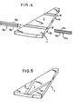
- FIG. 4 shows an embodiment of the invention in which hemsticks 35, 36 and 45, 46 for receiving stiffeners run in a circular arc and not radially as in the other embodiments. If necessary, such circular-arc-shaped stiffeners can be provided in addition to radial stiffeners.
- the U-legs 18a and 18b of the U-shaped fork 17a are inserted into the hemstitch 35 and 36 from one side and the U-legs 19a and 19b of the U-shaped fork 17b from the other side.
- the free ends of the two U-legs 19a and 19b arrive at the locations marked by arrows in the end openings of the U-legs 18a and 18b, which are designed as hollow profiles. With sufficient rigidity of the brackets, any additional mounting is unnecessary in this embodiment, since the two Fix each other in brackets.
- FIG. 5 shows a further exemplary embodiment of the invention, in which hemstuffs 55 and 65 practically run from a common point on the circumference of the filter cell 1 in a V-shape towards the center of the pane.
- This embodiment is particularly advantageous for very wide filter cells. Namely, it is a particularly large area of the filter cell through the embodiment illustrated in Figure 5 of the Principalsfnrm Erfindun sgenenstandes g such divided dministerkeine large bulge can occur more.
Abstract
Die Erfindung betrifft ein Filtertuch für Scheibenfilter mit insbesondere sektorförmigen Filterzellen aus einem Filtertuch. In dieses Filtertuch sind direkt Versteifungen in der Form von U-förmigen Klammern eingearbeitet und dort in Säumen oder Hohlsäumen oder Schlaufen festgelegt.The invention relates to a filter cloth for disc filters with in particular sector-shaped filter cells made of a filter cloth. Stiffeners in the form of U-shaped brackets are directly incorporated into this filter cloth and fixed there in hems or hemstitching or loops.
Description
Die Erfindung betrifft ein Filtertuch für ein Scheibenfilter mit insbesondere sektorförmigen und Versteifungen aufweisenden Filterzellen.The invention relates to a filter cloth for a disc filter with in particular sector-shaped and stiffening filter cells.
Bei Scheibenfiltern muß bekanntlich der während des Filtervorganges auf dem Filtertuch aufgewchsene Filterkuchen am Ende eines Filterzyklus abgehoben werden, was gewöhnlich mittels Druckluft geschieht, die in den Innenraum der Filterzelle eingeblasen wird. Der bei deisem Einblasen auf das Filtertuch einwirkende Druckluftstoß sollte an sich eine möglichst steil verlaufende Flanke des Druckluftanstiegprofils haben, damit sich der Filterkuchen vollständig vom Filtertuch lösen kann. Eine zu starke Ausbauchung des Filtertuches ist dabei aber nicht erwünscht, weil eine zu große Luftmenge in die Zelle geblasen werden muß. Dies bedeutet einen hohen Luftverbrauch und damit einen unerwünschten Energieverbrauch. Außerdem wird die Blaszeit zu lange, so daß keine höheren Drehzahlen gefahren werden können. Die Überschneidungszeit reicht nicht aus, um den Innenraum des Beutels mit Luft zu füllen. Ein weiterer Nachteil besteht darin, daß die großen Ausbauchungen auch große Spannungen im Filtertuch hervorrufen, durch welche dessen Lebensdauer vermindert wird.In the case of disc filters, it is known that the filter cake grown on the filter cloth during the filtering process must be lifted off at the end of a filter cycle, which is usually done by means of compressed air which is blown into the interior of the filter cell. The blast of compressed air acting on the filter cloth when blowing in should in itself have the steepest possible flank of the compressed air rise profile so that the filter cake can completely detach from the filter cloth. Excessive bulging of the filter cloth is not desirable, however, because too much air has to be blown into the cell. This means high air consumption and thus undesirable energy consumption. In addition, the blowing time is too long, so that higher speeds can not be driven. The overlap time is not sufficient to fill the interior of the bag with air. Another disadvantage is that the large bulges also cause large tensions in the filter cloth, which reduces its service life.
Ein weiterer Nachteil des stark ausgebauchten Filtertuchs besteht darin, daß die Luft nicht rasch genug entweichen kann und das Filtertuch somit im aufgeblasenen Zustand den Schaber passiert und dort entlang streift.Another disadvantage of the heavily bulged filter cloth is that the air cannot escape quickly enough and the filter cloth thus passes the scraper when it is inflated and grazes there.
Ein derartiges Scheibenfilter weist also zwei Lochplatten auf, auf denen das Filtertuch mittels Klemmleisten eingespannt ist. Diese Klemmleisten können dabei radial und/oder kreisbogenförmig und/oder sternförmig oder auch tellerförmig verlaufen. Wesentlich ist aber, daß bei diesem bestehenden Scheibenfilter zum Festlegen des Filtertuches zusätzlich zu den Lochplatten noch Klemmleisten benötigt werden, um so zu starke Ausbauchungen des Filtertuches auszuschließen. Eine Umrüstung bestehender Filteranlagen ist nicht unproblematisch, da Lochplatten und Klemmleisten entsprechend angepaßt werden müssen, damit die unerwünschten starken Ausbauchungen sicher ausgeschlossen sind. Es ist daher Aufgabe der Erfindung, ein Filtertuch zu schaffen, bei dem auf einfache Weise starke Ausbauchungen während der Drucklufteinwirkung zum Abheben des Filterkuchens ausgeschlossen sind.Such a disc filter therefore has two perforated plates on which the filter cloth is clamped by means of clamping strips. These terminal strips can run radially and / or in the form of an arc of a circle and / or in the shape of a star or a plate. It is essential, however, that in this existing disc filter to fix the filter cloth, in addition to the perforated plates, clamping strips are required in order to rule out excessive bulges of the filter cloth. Retrofitting existing filter systems is not without problems, since perforated plates and terminal strips have to be adapted accordingly, so that the undesired strong bulges are safely excluded. It is therefore an object of the invention to provide a filter cloth in which strong bulges during the action of compressed air to remove the filter cake are excluded in a simple manner.
Diese Aufgabe wird erfindungsgemäß dadurch gelöst, daß die Versteifungen direkt in das Gewebe des Filtertuches einbezogen sind.This object is achieved in that the stiffeners are included directly in the fabric of the filter cloth.
Bei der Erfindung ist also kein Zusammenwirken von Klemmleisten und Lochplatten erforderlich, um die gewünschten Versteifungen für das Filtertuch zu bewirken. Vielmehr sind diese Versteifungen direkt in das Filtertuch einbezogen, so daß es beim Umrüsten einer bestehenden Filteranlage ausreichend ist, wenn das Filtertuch allein mit seinen Versteifungen an diese Anlage angepaßt wird.In the invention, therefore, no interaction of terminal strips and perforated plates is required in order to bring about the desired stiffening for the filter cloth. Rather, these stiffeners are included directly in the filter cloth, so that when converting an existing filter system, it is sufficient if the filter cloth alone is adapted to this system with its stiffeners.
In einer vorteilhaften Weiterbildung der Erfindung ist vorgesehen, daß die Versteifungen aus Metall oder Kunststoff oder anderem steifen Material bestehende U-förmige Klammern sind, deren Schenkel- oder Endabstand der Scheibenfilter-Segmentdicke angepaßt ist. Die Klammern können dabei ein Flachprofil oder ein Rundprofil haben.In an advantageous development of the invention it is provided that the stiffeners made of metal or plastic or other rigid material are U-shaped brackets, the leg or end distance of which is adapted to the disc filter segment thickness. The brackets can have a flat profile or a round profile.
Diese Klammern werden mit ihren Schenkeln beispielsweise in einem durch die Nahtstelle von zwei Filtertaschenhälften gebildeten Saum oder in einem durch Aufnähen eines bandförmigen Gewebestückes auf das Gewebe des Filtertuches erhaltenen Hohlsaum oder in auf dem Gewebe des Filtertuches angebrachten Schlaufen festgelegt, wodurch es auf einfache Weise möglich ist, die die Versteifungen bildenden Klammern in das Gewebe des Filtertuches einzubeziehen: es genügt, wenn die freien Enden oder Schenkel der Klammern in die Säume bzw. Hohlsäume bzw. Laschen eingeschoben werden, wodurch gleichzeitig die Scheibenfilter-Segmentdicke festgelegt wird.These clamps are fixed with their legs, for example, in a hem formed by the seam of two filter bag halves or in a hemstitch obtained by sewing a band-shaped piece of fabric onto the fabric of the filter cloth or in loops attached to the fabric of the filter cloth, making it possible in a simple manner to include the stiffening brackets in the fabric of the filter cloth: it is sufficient if the free ends or legs of the brackets are inserted into the hems or hemstitch or tabs, whereby the disc filter segment thickness is determined at the same time.
Zusätzlich können die Enden der Schenkel der Klammern noch durch Laschen fixiert werden, wodurch eine besonders sichere Verbindung zwischen Gewebe und Klammern erreicht wird. Auch ist es möglich, die Enden der Schenkel der Klammern noch durch eine weitere, an der Außenseite auf das Gewebe des Filtertuches angebrachte Klammer oder Bride zu fixieren.In addition, the ends of the limbs of the clips can be fixed with tabs, which results in a particularly secure connection between the tissue and clips. It is also possible to fix the ends of the limbs of the clips by means of a further clip or clip attached to the outside of the filter cloth.
Die Versteifungen können radial und/oder kreisbogenförmig verlaufen. Wichtig ist lediglich, daß die Versteifungen derart geführt sind, daß übermäßige Ausbauchungen des Filtertuches während der Drucklufteinwirkung vermieden sind.The stiffeners can run radially and / or in a circular arc. It is only important that the stiffeners are guided in such a way that excessive bulges of the filter cloth during the action of compressed air are avoided.
Die Versteifungen können außerdem fest in das Gewebe eingearbeitet sein, d.h., die Versteifungen in Form von Flachprofilen oder Rundprofilen können fest beispielsweise in Hohlsäume des Gewebes eingenäht sein.The stiffeners can also be firmly incorporated into the fabric, i.e. the stiffeners in the form of flat profiles or round profiles can be sewn firmly into, for example, hemstitching of the fabric.
Schließlich ist es auch möglich, daß eine Filterzelle mehrere Versteifungen aufweist, was insbesondere dann gilt, wenn diese Filterzelle eine relativ große Oberfläche besitzt, so daß größere Ausbauchungen zu befürchten sind.Finally, it is also possible for a filter cell to have a plurality of stiffeners, which is particularly true if this filter cell has a relatively large surface area, so that larger bulges are to be feared.
Das Material für die Versteifungen bzw. Klammern wird abhängig von dem beabsichtigten Einsatz des Scheibenfilters gewählt. Sollten mit dem Scheibenfilter besonders aggresive Materialien behandelt werden, so bestehen die Versteifungen in zweckmäßiger Weise aus Edelstahl oder aus einem geeigneten Kunststoff.The material for the stiffeners or brackets is selected depending on the intended use of the disc filter. If particularly aggressive materials are treated with the disc filter, the stiffeners are suitably made of stainless steel or a suitable plastic.
Das erfindungsgemäße Filtertuch kann auch zusammen mit einer Lochplatte verwendet werden, auf deren Oberfläche es aufgelegt wird. Dies wird insbesondere dann der Fall sein, wenn das Scheibenfilter einen relativ großen Durchmesser besitzt. Für kleinere Durchmesser ist aber eine derartige Lochplatte nicht erforderlich.The filter cloth according to the invention can also be used together with a perforated plate, on the surface of which it is placed. This will be the case in particular if the disc filter has a relatively large diameter. Such a perforated plate is not required for smaller diameters.
Wenn die Lochplatte konkav ausgebildet ist, damit das mit Druckluft zu füllende Volumen möglichst klein gehalten ist, dann sollten die Versteifungen ebenfalls entsprechend der Lochplatte konkav geformt sein, damit das Filtertuch an die konkave Oberfläche der Lochplatte angepaßt ist.If the perforated plate is concave so that the volume to be filled with compressed air is kept as small as possible, then the stiffeners should also be concave in accordance with the perforated plate so that the filter cloth is adapted to the concave surface of the perforated plate.
Die Erfindung ermöglicht ein Filtertuch für ein Scheibenfilter, bei dem die Versteifungen direkt in das Gewebe des Filtertuches einbezogen sind, so daß keine besonderen Maßnahmen vorgesehen werden müssen, die in einem Zusammenwirken von Klemmleisten und einer Lochplatte lediglich zum Festlegen des Filtertuches bestehen.The invention enables a filter cloth for a disc filter, in which the stiffeners are included directly in the fabric of the filter cloth, so that no special measures have to be provided, which consist in an interaction of K clamping strips and a perforated plate only for fixing the filter cloth.
Nachfolgend wird die Erfindung anhand der Zeichnung näher erläutert, in deren Figuren 1 bis 5 jeweils eine sektorförmige Filterzelle des Filtertuches gezeigt ist.The invention is explained in more detail below with reference to the drawing, in which FIGS. 1 to 5 each show a sector-shaped filter cell of the filter cloth.
In Fig. 1 ist eine sektorförmige Filterzelle 1 gezeigt, die aus einem Filtertuch 2 besteht, das zwei Filtertaschenhälften bildet. Durch Aufnähen von bandförmigen Gewebestücken 3,4 entstehen zwei Hohlsäume 5,6, in die eine Klammer 7 aus Metall oder Kunststoff oder einem anderen steifen Material mit einem Flachprofil eingeschoben werden kann. Diese Klammer 7 hat eine U-förmige Gestalt und weist Schenkel 8,9 auf, die jeweils in den Hohlsäumen 5,6 festgelegt werden. Der Abstand d zwischen den Schenkeln 8,9 der Klammer 7 ist genau an die Scheibenfilter-Segmentdicke d angepaßt. Wenn also die Schenkel 8,9 der Klammer 7 in die Hohlsäume 5,6 der Filterzelle 1 eingeschoben sind, dann wird diese Filterzelle 1 durch die Klammer 7 in ihrer Segmentdicke versteift.In Fig. 1, a sector-shaped filter cell 1 is shown, which consists of a
Zusätzlich können am Kopfende der Filterzelle 1 noch beispielsweise zwei Laschen 10,11 vorgesehen sein, durch die die Enden der Schenkel 8,9 der Klammer 7 besonders sicher fixiert werden.In addition, two tabs 10, 11 can be provided at the head end of the filter cell 1, for example, by means of which the ends of the legs 8, 9 of the clamp 7 are fixed particularly securely.
Die Laschen 10 und 11 werden auf dem aus Kunststoff oder Metall oder einem anderen entsprechenden Material hergestellten Filtersegment angebracht, so daß die Schenkelenden der Klammern einen zusätzlichen Halt bekommen. Es ist auch möglich, eine zusätzliche Klammer oder Bride an der Außenseite auf dem Gewebe derart anzubringen, daß die Enden der Schenkel 8, 9 der Klammer 7 besonders gut fixiert sind.The tabs 10 and 11 are attached to the filter segment made of plastic or metal or another corresponding material, so that the leg ends of the clips get an additional hold. It is also possible to attach an additional clip or clip to the outside of the fabric in such a way that the ends of the legs 8, 9 of the clip 7 are particularly well fixed.
Fig. 2 zeigt ein weiteres Ausführungsbeispiel der Erfindung, bei dem der Schenkel 3 der Klammer 7 durch Schlaufen 12 festgelegt wird, die auf die Oberfläche des Filtertuches 2 aufgenäht sind. Selbstverständlich ist es auch möglich, diese Schlaufen 12 auf der Innenseite des Filtertuches 2 vorzusehen.Fig. 2 shows a further embodiment of the invention, in which the leg 3 of the clamp 7 is fixed by
In Fig. 3 ist eine Filterzelle 1 mit besonders großer Filtersegmentfläche dargestellt. Um die gewünschte Versteifung zu erzielen, ist diese Filtersegmentfläche durch` mehrere Hohlsäume 5, 6, 15, 16 und 25, 26 unterteilt. Anstelle dieser Hohlsäume können selbstverständlich auch Schlaufen entsprechend dem Ausführungsbeispiel der Fig. 2 vorgesehen werden.3 shows a filter cell 1 with a particularly large filter segment area. In order to achieve the desired stiffening, this filter segment surface is divided by several
In Fig. 4 ist ein Ausführungsbeispiel der Erfindung dargestellt, bei dem Hohlsäume 35, 36 und 45, 46 zur Aufnahme von Versteifungen kreisbogenförmig und nicht radial wie in den übrigen Ausführungsbeispielen verlaufen. Gegebenenfalls können solche kreisbogenförmige Versteifungen zusätzlich zu radialen Versteifungen vorgesehen werden. In die Hohlsäume 35 und 36 werden von der einen Seite die U-Schenkel 18a und 18b der U-förmigen Gabel 17a und von der anderen Seite die U-Schenkel 19a und 19b der U-förmigen Gabel 17b eingeschoben. Dabei gelangen die freien Enden der beiden U-Schenkel 19a und 19b an den durch Pfeile markierten Stellen in die stirnseitigen Öffnungen der U-Schenkel 18a und 18b, welche als Hohlprofile ausgebildet sind. Bei hinreichender Steifigkeit der Klammern erübrigt sich bei dieser Ausführungsform jegliche zusätzliche Halterung, da die beiden Klammern sich gegenseitig fixieren.FIG. 4 shows an embodiment of the invention in which
In der Fig. 5 ist ein weiteres Ausführungsbeispiel der Erfindung dargestellt, bei welchem Hohlsäume 55 und 65 praktisch von einem gemeinsamen Punkt am Umfang der Filterzelle 1 aus V-förmig zur Scheibenmitte hin verlaufen. Diese Ausführungsform ist besonders für sehr breite Filterzellen vorteilhaft. Es wird nämlich eine besonders große Fläche der Filterzelle durch die in der Fig 5 dargestellte Ausführungsfnrm des Erfindungsgenenstandes derart unterteilt, daßkeine große Ausbauchung mehr auftreten kann.5 shows a further exemplary embodiment of the invention, in which
Claims (14)
Applications Claiming Priority (2)
| Application Number | Priority Date | Filing Date | Title |
|---|---|---|---|
| DE3329117 | 1983-08-11 | ||
| DE3329117A DE3329117A1 (en) | 1983-08-11 | 1983-08-11 | FILTER CLOTH FOR DISC FILTER |
Publications (2)
| Publication Number | Publication Date |
|---|---|
| EP0141082A2 true EP0141082A2 (en) | 1985-05-15 |
| EP0141082A3 EP0141082A3 (en) | 1987-08-19 |
Family
ID=6206371
Family Applications (1)
| Application Number | Title | Priority Date | Filing Date |
|---|---|---|---|
| EP84109501A Withdrawn EP0141082A3 (en) | 1983-08-11 | 1984-08-09 | Filter cloth for disc filters |
Country Status (4)
| Country | Link |
|---|---|
| US (1) | US4578192A (en) |
| EP (1) | EP0141082A3 (en) |
| DE (1) | DE3329117A1 (en) |
| FI (1) | FI843164A (en) |
Families Citing this family (6)
| Publication number | Priority date | Publication date | Assignee | Title |
|---|---|---|---|---|
| SE9001807L (en) * | 1990-05-18 | 1991-11-11 | Celleco Hedemora Ab | SILDUCK DEVICE FOR ROTATING FILTERS |
| ATE249869T1 (en) † | 2001-02-20 | 2003-10-15 | Sefar Ag | FILTER CLOTH |
| US8252181B2 (en) * | 2007-07-19 | 2012-08-28 | Gerald Pitre | Horizontal ore filter with replaceable filter elements |
| EP2203231B1 (en) * | 2007-09-26 | 2011-08-10 | Gaudfrin | Disc filtration device |
| US9669338B2 (en) * | 2015-03-11 | 2017-06-06 | GL & V Luxembourg Sàrl | Disc filter and a method of constructing a disc filter sector |
| US11000791B2 (en) * | 2019-03-06 | 2021-05-11 | Veolia Water Solutions & Technologies Support | Rotary disc filter having backwash guides |
Citations (4)
| Publication number | Priority date | Publication date | Assignee | Title |
|---|---|---|---|---|
| GB764500A (en) * | 1953-07-16 | 1956-12-28 | Peterson Filters & Eng | Coutinuous filter and method of operation thereof |
| DE1930046A1 (en) * | 1969-06-13 | 1971-02-11 | Ardie Werk Gmbh | Method and device for switching multi-stage gear change transmissions |
| DE2144806A1 (en) * | 1971-09-08 | 1973-03-15 | Joseph Dipl Ing Brokhage | Filter cloth with mesh backing - has plastics or adhesive attachments between these |
| US4362622A (en) * | 1981-03-30 | 1982-12-07 | Ingersoll-Rand Company | Filter |
Family Cites Families (9)
| Publication number | Priority date | Publication date | Assignee | Title |
|---|---|---|---|---|
| US1240385A (en) * | 1914-05-09 | 1917-09-18 | Ernest J Sweetland | Filter. |
| US1878384A (en) * | 1929-04-18 | 1932-09-20 | Hoover Co | Suction cleaner |
| US1894884A (en) * | 1930-05-07 | 1933-01-17 | Warren E Page | Vacuum cleaner bag attachment |
| US2338549A (en) * | 1941-08-01 | 1944-01-04 | Us Rubber Co | Filter bag |
| FR1059010A (en) * | 1951-04-05 | 1954-03-22 | Tecalemit | Fluid filters |
| NL238623A (en) * | 1958-04-29 | |||
| US3165473A (en) * | 1960-10-24 | 1965-01-12 | Pall Corp | Corrugated filter unit |
| US3807146A (en) * | 1967-02-21 | 1974-04-30 | H Witkowski | Mold for making a filter |
| GB1544822A (en) * | 1976-03-26 | 1979-04-25 | Process Scient Innovations | Filter elements for gas or liquid and methods of making such elements |
-
1983
- 1983-08-11 DE DE3329117A patent/DE3329117A1/en not_active Withdrawn
-
1984
- 1984-08-09 EP EP84109501A patent/EP0141082A3/en not_active Withdrawn
- 1984-08-10 FI FI843164A patent/FI843164A/en not_active Application Discontinuation
- 1984-08-10 US US06/639,404 patent/US4578192A/en not_active Expired - Fee Related
Patent Citations (4)
| Publication number | Priority date | Publication date | Assignee | Title |
|---|---|---|---|---|
| GB764500A (en) * | 1953-07-16 | 1956-12-28 | Peterson Filters & Eng | Coutinuous filter and method of operation thereof |
| DE1930046A1 (en) * | 1969-06-13 | 1971-02-11 | Ardie Werk Gmbh | Method and device for switching multi-stage gear change transmissions |
| DE2144806A1 (en) * | 1971-09-08 | 1973-03-15 | Joseph Dipl Ing Brokhage | Filter cloth with mesh backing - has plastics or adhesive attachments between these |
| US4362622A (en) * | 1981-03-30 | 1982-12-07 | Ingersoll-Rand Company | Filter |
Also Published As
| Publication number | Publication date |
|---|---|
| FI843164A (en) | 1985-02-12 |
| FI843164A0 (en) | 1984-08-10 |
| US4578192A (en) | 1986-03-25 |
| EP0141082A3 (en) | 1987-08-19 |
| DE3329117A1 (en) | 1985-02-28 |
Similar Documents
| Publication | Publication Date | Title |
|---|---|---|
| DE69835963T2 (en) | HUB FILTER | |
| EP0982433B1 (en) | Screening cylinder for a pressure screening device having a replaceable cylindrical screen | |
| DE2218461B2 (en) | Device for attaching the filter bags of bag filters | |
| DE1948774C3 (en) | Filter insert for precoat filtration | |
| DE2551866C3 (en) | Device for installing bag filter assemblies | |
| DE2249603A1 (en) | FILTER ELEMENT | |
| DE2351407A1 (en) | CLAMPING DEVICE FOR A PRESSURE VESSEL | |
| EP0141082A2 (en) | Filter cloth for disc filters | |
| DE3331770A1 (en) | FILTER UNIT AND DETACHABLE FILTER TO CONNECT TO ANOTHER FILTER | |
| WO2015124306A1 (en) | Device for filtering a plastic melt | |
| DE4432004C2 (en) | Device for attaching filter media to filter elements | |
| EP0699465A2 (en) | Air-filter | |
| DE4135359C1 (en) | ||
| DE202019004268U1 (en) | Filtering device for plastic melts | |
| EP0442891B1 (en) | Process and device for folding back the membrane of a pressure filter for suspensions | |
| DE2655273B2 (en) | Ventilation grilles, in particular for rail vehicles | |
| DE2322452B2 (en) | Filter press element | |
| DE10012534C2 (en) | Solid-liquid filter process and system for wastewater and the like | |
| EP0352404B1 (en) | Filter element | |
| EP4272852A1 (en) | Filter bag and filter module for a rotary disc filter, and rotary disc filter | |
| DE1461413C3 (en) | Filter candle with wire mesh jacket | |
| EP0037498B1 (en) | Apparatus for a bag filter | |
| DE927858C (en) | Process for the production of clamping edges on wire meshes for wire mesh floors u. like | |
| DE829244C (en) | Filter device for milk and similar liquids | |
| DE3202227C2 (en) | Row bag filter |
Legal Events
| Date | Code | Title | Description |
|---|---|---|---|
| PUAI | Public reference made under article 153(3) epc to a published international application that has entered the european phase |
Free format text: ORIGINAL CODE: 0009012 |
|
| AK | Designated contracting states |
Designated state(s): CH FR GB IT LI SE |
|
| 17P | Request for examination filed |
Effective date: 19851030 |
|
| PUAL | Search report despatched |
Free format text: ORIGINAL CODE: 0009013 |
|
| AK | Designated contracting states |
Kind code of ref document: A3 Designated state(s): CH FR GB IT LI SE |
|
| 17Q | First examination report despatched |
Effective date: 19880204 |
|
| STAA | Information on the status of an ep patent application or granted ep patent |
Free format text: STATUS: THE APPLICATION IS DEEMED TO BE WITHDRAWN |
|
| 18D | Application deemed to be withdrawn |
Effective date: 19880615 |
|
| RIN1 | Information on inventor provided before grant (corrected) |
Inventor name: MUELLER, HANS-RUDOLF |