EP0140876B1 - Vorrichtung in einem eine rotierende achse tragenden element - Google Patents
Vorrichtung in einem eine rotierende achse tragenden element Download PDFInfo
- Publication number
- EP0140876B1 EP0140876B1 EP82903487A EP82903487A EP0140876B1 EP 0140876 B1 EP0140876 B1 EP 0140876B1 EP 82903487 A EP82903487 A EP 82903487A EP 82903487 A EP82903487 A EP 82903487A EP 0140876 B1 EP0140876 B1 EP 0140876B1
- Authority
- EP
- European Patent Office
- Prior art keywords
- retainer
- screws
- clamping ring
- plate
- bearing
- Prior art date
- Legal status (The legal status is an assumption and is not a legal conclusion. Google has not performed a legal analysis and makes no representation as to the accuracy of the status listed.)
- Expired
Links
- 235000000396 iron Nutrition 0.000 claims description 5
- 229910000746 Structural steel Inorganic materials 0.000 claims description 2
- XEEYBQQBJWHFJM-UHFFFAOYSA-N Iron Chemical compound [Fe] XEEYBQQBJWHFJM-UHFFFAOYSA-N 0.000 description 4
- 230000005540 biological transmission Effects 0.000 description 2
- 229910052742 iron Inorganic materials 0.000 description 2
- 239000002184 metal Substances 0.000 description 2
- 229910052751 metal Inorganic materials 0.000 description 2
- 230000001681 protective effect Effects 0.000 description 2
- 230000008878 coupling Effects 0.000 description 1
- 238000010168 coupling process Methods 0.000 description 1
- 238000005859 coupling reaction Methods 0.000 description 1
- 238000006073 displacement reaction Methods 0.000 description 1
- 230000000694 effects Effects 0.000 description 1
- 229920003023 plastic Polymers 0.000 description 1
- 239000004033 plastic Substances 0.000 description 1
- 230000000717 retained effect Effects 0.000 description 1
Images


Classifications
-
- F—MECHANICAL ENGINEERING; LIGHTING; HEATING; WEAPONS; BLASTING
- F16—ENGINEERING ELEMENTS AND UNITS; GENERAL MEASURES FOR PRODUCING AND MAINTAINING EFFECTIVE FUNCTIONING OF MACHINES OR INSTALLATIONS; THERMAL INSULATION IN GENERAL
- F16C—SHAFTS; FLEXIBLE SHAFTS; ELEMENTS OR CRANKSHAFT MECHANISMS; ROTARY BODIES OTHER THAN GEARING ELEMENTS; BEARINGS
- F16C35/00—Rigid support of bearing units; Housings, e.g. caps, covers
- F16C35/04—Rigid support of bearing units; Housings, e.g. caps, covers in the case of ball or roller bearings
- F16C35/06—Mounting or dismounting of ball or roller bearings; Fixing them onto shaft or in housing
- F16C35/067—Fixing them in a housing
-
- B—PERFORMING OPERATIONS; TRANSPORTING
- B65—CONVEYING; PACKING; STORING; HANDLING THIN OR FILAMENTARY MATERIAL
- B65G—TRANSPORT OR STORAGE DEVICES, e.g. CONVEYORS FOR LOADING OR TIPPING, SHOP CONVEYOR SYSTEMS OR PNEUMATIC TUBE CONVEYORS
- B65G39/00—Rollers, e.g. drive rollers, or arrangements thereof incorporated in roller-ways or other types of mechanical conveyors
- B65G39/10—Arrangements of rollers
- B65G39/12—Arrangements of rollers mounted on framework
-
- F—MECHANICAL ENGINEERING; LIGHTING; HEATING; WEAPONS; BLASTING
- F16—ENGINEERING ELEMENTS AND UNITS; GENERAL MEASURES FOR PRODUCING AND MAINTAINING EFFECTIVE FUNCTIONING OF MACHINES OR INSTALLATIONS; THERMAL INSULATION IN GENERAL
- F16C—SHAFTS; FLEXIBLE SHAFTS; ELEMENTS OR CRANKSHAFT MECHANISMS; ROTARY BODIES OTHER THAN GEARING ELEMENTS; BEARINGS
- F16C13/00—Rolls, drums, discs, or the like; Bearings or mountings therefor
- F16C13/02—Bearings
Definitions
- the subject invention relates to a mounting device for use with a bearing element devised to support a rotating shaft incorporated in a machine or the like, wherein the bearing housing of each individual bearing element is fastened to a machine member by means of a locking ring formed with a first set of screw holes through which pass a first set of screws, to be anchored to the bearing housing with the machine member sandwiched therebetween.
- Fig. 1 is a partly broken vertical longitudinal sectional view through a conveyor roller comprising a bearing element equipped with a device in accordance with the invention provided with a retainer element of a first type
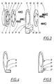
- Fig. 2 is a lateral view of the device in accordance with the invention, equipped with a retainer element of a second type.
- Fig. 3 is an exploded view of the device in accordance with the invention comprising a retainer element of said second type
- Fig. 4 is a perspective view of the retainer element of the first type
- Fig. 5 is a perspective view of a retainer element of a third type
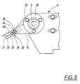
- Fig. 6 is a partly broken lateral view of a conveyor equipped with the device in accordance with the invention
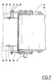
- Fig. 7 is a partly broken view from below of the conveyor in accordance with Fig. 6.
- the bearing element 1 and thus also the rotating shaft 2 and the conveyor roller 3 are maintained in their supported position by the lateral wall 7 because the bearing housing 9 is secured in position in the recess 10 by means of a locking ring 11, see also Fig. 3.
- the latter is retained in position by means of a number of screws 12, three in accordance with the example shown.
- the screws pass through corresponding holes 13 which are countersunk in the locking ring in order to accommodate the countersunk heads of the screws and which are positioned symmetrically at even-pitch spacings along the periphery of the locking ring.
- the screws 12 are screwed into correspondingly positioned threaded bores 14 formed in the bearing housing. Because the annular recessed portion 8 of the bearing housing has a depth which does not exceed the thickness of the lateral wall 7 a positive fastening effect is obtained.
- the device in accordance with the invention consists of a retainer element 15 which is intended to be secured to the bearing element in accordance with the invention by means of a clamping ring 16.
- the retainer element 15 comprises an attachment plate 17 in which is formed a circular aperture 18, and a retainer means 19 which could be of different types, depending on the application.
- the purpose of the retainer means 19 of the retainer element 15 is to support and fasten various members and details incorporated in or associated with the machine. One example thereof will be described in closer detail in the following with reference to Figs. 6 and 7.
- the clamping ring 16 likewise is formed with an aperture 20 the diameter size of which is not particularly decisive but which is intended to provide space for the projecting rotating shaft 2 and its associated protective hood and possibly also to serve to fasten the latter by clamping a flange on the hood.
- the clamping ring 16 further is formed with a number of holes 21, three in accordance with the example illustrated, which holes are positioned symmetrically at even pitch along the periphery of the ring and are designed to receive screws 22 therein.
- the locking ring 11 and the bearing housing 5 are formed with a second set of holes 23, 24 for this second set of screws 22.
- the second set of holes 23, 24 in the locking ring and the bearing housing are angularly displaced relative to the first set of bores 14, for instance in such a manner that they will be positioned symmetrically between the first set of holes and bores.
- the second set of screws 22 extends through the circular aperture 18 formed in the retainer element 15 and thus serves to tighten the clamping ring 16 against the attachment plate 17 of the retainer element and thus to fasten the latter when they are screwed into the second set of bores 24 formed in the bearing housing 9.
- the screws 22 fastening the clamping ring 16 are spaced equal radial distances from the centre of the ring, this radial distance being so chosen relative to the aperture 18 formed in the attachment plate 17 of the retainer element 15 that the screws will form a guiding means to guide the retainer element 15 radially, as best appears from Fig. 2, ensuring that the latter element is positioned centrally with its aperture 18 essentially coaxial with the symmetry axis of the bearing element, that is, with the rotating shaft 2, whereas the locking ring 11 and the clamping ring 16 on either side of the attachment plate will form guiding means for guidance axially.
- the screws 22 When the screws 22 are slightly loosened, that is when they are unscrewed somewhat over a few turns from their fully screwed-in position, the screws together with the clamping ring 16 will form supports on which the retainer element 15 rests while being allowed to be turned relative to the bearing housing 9 to any desired rotational position as a result of the above-referred to cooperation between the periphery of the aperture 18 and the external faces of the screws 22.
- the screws 22 are tightened and the retainer element 15 is maintained securely in position.
- Fig. 4 illustrates in a perspective view a retainer element 15 of the same type as the one shown in Fig. 1 but being formed with a retainer means 19 which is in the from of a tubular piece projecting laterally from the attachment plate 17.
- the tubular piece is hollow and open at both ends and extends through the attachment plate 17.
- This type of retainer element may be used for a variety of purposes and applications and one example of usage is shown in Figs. 6 and 7 as will be described in closer detail in the following.
- the retainer means 19 in accordance with Fig. 4 could also be used as a holder means to support the mounting shaft of a supplementary conveyor roller or the like.
- FIG. 3 A second type of retainer element is shown in the exploded view of Fig. 3, wherein the retainer element retainer means is designated by numeral 25.
- This retainer means is in the form of a piece of box-shaped profile member having two screw holes 26 formed therein.
- This type of retainer element may be used to secure support legs or similar details on which the conveyor is supported.
- the support leg When the retainer means is disposed horizontally as illustrated in Fig. 3, the support leg may be in the form of a horizontal bracket member which is anchored in a neighbouring wall of the premises.
- the device in accordance with the subject invention thus makes it possible to set the retainer means 25 in any desired rotational position relative to the rotating shaft 2 and then be fastened in this position.
- Fig. 5 shows an example of yet another type of retainer element 15 comprising a retainer means 27 in the form of an angle iron in which are formed elongate slots 28.
- This type of retainer element allows any required detail to be fastened by screws in the desired angular position relative to the rotating shaft.
- Figs. 6 and 7 show an example of a member designed to be fastened to the bearing element by means of a retainer element 15 of the invention.
- the supported member is a transfer plate 29 which is disposed at one end of a belt conveyor 4 in order e.g. to allow objects advanced on the conveyor to be transferred from or to the conveyor belt 40 to ensure that they are not entrained on the belt return path but are transported further to a collection point or to the following conveyor.
- the transfer plate 29 is formed on its lower face with two fixed attachment irons 30 each one of which is formed with an elongate slot 31.
- the retainer element of this example is, as mentioned previously, of the first type shown in Figs. 1 and 4 and is connected with a connecting member 32.
- the latter is in the form of an attachment iron 33 and a threaded pin 34 which is secured to one end of the iron and extends through the retainer means 19 and supports a nut 35 at one of its ends.
- the two attachment irons 30 of the transfer plate 29 are joined to the connecting members 32 by means of a screw 36 and a nut 37.
- the transfer plate 29 may be set in any desired position relative to the belt of the conveyor and the rotating shaft 2.
- the vertical position of the transfer plate that is, the position of the retainer means 19, may be set in accordance with the invention by rotating the retainer element about the rotating shaft 2 after the tightening screws 22 have been loosened, said screws being again tightened as soon as the chosen position is set.
- Further angular positions of the transfer plate 29 are possible by pivoting the plate about the retainer means, the nut 35 having been loosened. Adjustment of the trailing end 38 of the transfer plate relative to the conveyor belt 40 is possible by displacement of the attachment irons 30, 33 relative to one another after loosening of the screw 36 and the nut 37.
- the invention is not limited to the embodiments described in the aforegoing and illustrated in the drawings but a number of variations are possible within the scope of the appended claims.
- the number of screws and their positions could be chosen differently.
- the retainer element could have a different configuration and be equipped with other retainer means than those shown, depending on the intended application. It is likewise possible in one and the same bearing element to mount more than one retainer element, for instance two such elements, with the aid of one and the same clamping ring.
Landscapes
- Engineering & Computer Science (AREA)
- General Engineering & Computer Science (AREA)
- Mechanical Engineering (AREA)
- Shafts, Cranks, Connecting Bars, And Related Bearings (AREA)
- Mounting Of Bearings Or Others (AREA)
- Rollers For Roller Conveyors For Transfer (AREA)
- Connection Of Motors, Electrical Generators, Mechanical Devices, And The Like (AREA)
- Rolling Contact Bearings (AREA)
- Golf Clubs (AREA)
- Executing Machine-Instructions (AREA)
- Reduction Or Emphasis Of Bandwidth Of Signals (AREA)
- Sliding-Contact Bearings (AREA)
- Motor Or Generator Frames (AREA)
- Support Of The Bearing (AREA)
- Load-Engaging Elements For Cranes (AREA)
Claims (7)
Priority Applications (1)
| Application Number | Priority Date | Filing Date | Title |
|---|---|---|---|
| AT82903487T ATE25543T1 (de) | 1982-11-15 | 1982-11-15 | Vorrichtung in einem eine rotierende achse tragenden element. |
Applications Claiming Priority (1)
| Application Number | Priority Date | Filing Date | Title |
|---|---|---|---|
| PCT/SE1982/000387 WO1984001986A1 (en) | 1982-11-15 | 1982-11-15 | A device in a rotating shaft supporting bearing element |
Publications (2)
| Publication Number | Publication Date |
|---|---|
| EP0140876A1 EP0140876A1 (de) | 1985-05-15 |
| EP0140876B1 true EP0140876B1 (de) | 1987-02-25 |
Family
ID=20345815
Family Applications (1)
| Application Number | Title | Priority Date | Filing Date |
|---|---|---|---|
| EP82903487A Expired EP0140876B1 (de) | 1982-11-15 | 1982-11-15 | Vorrichtung in einem eine rotierende achse tragenden element |
Country Status (8)
| Country | Link |
|---|---|
| US (1) | US4593811A (de) |
| EP (1) | EP0140876B1 (de) |
| AT (1) | ATE25543T1 (de) |
| AU (1) | AU9127882A (de) |
| DE (1) | DE3275477D1 (de) |
| DK (1) | DK155623C (de) |
| NO (1) | NO156141C (de) |
| WO (1) | WO1984001986A1 (de) |
Families Citing this family (4)
| Publication number | Priority date | Publication date | Assignee | Title |
|---|---|---|---|---|
| DE102007027932A1 (de) * | 2007-06-18 | 2009-01-02 | Interroll-Holding Ag | Über Lagertöpfe gelagerte Förderrolle |
| CN103470639A (zh) * | 2013-09-13 | 2013-12-25 | 天津明贤科技有限公司 | 轴承密封端板 |
| KR200487786Y1 (ko) * | 2017-10-16 | 2018-10-31 | 박효준 | 컨베이어용 롤러 |
| DE102019207973A1 (de) * | 2019-05-29 | 2020-12-03 | Robert Bosch Gmbh | Handwerkzeugmaschine |
Family Cites Families (8)
| Publication number | Priority date | Publication date | Assignee | Title |
|---|---|---|---|---|
| DE844880C (de) * | 1944-08-17 | 1952-07-24 | Maschf Augsburg Nuernberg Ag | Reinigungsvorrichtung fuer Foerderbaender mit zwei hintereinanderliegenden Abstreifern |
| DE1059348B (de) * | 1956-08-08 | 1959-06-11 | Eickhoff Geb | Antriebstrommel fuer Foerderbaender |
| GB1209256A (en) * | 1968-04-23 | 1970-10-21 | Bsr Ltd | Improved bearing assembly |
| US3519121A (en) * | 1968-08-05 | 1970-07-07 | Cincinnati Milling Machine Co | Support structure for endless band |
| DE2105755C3 (de) * | 1971-02-08 | 1975-09-18 | Gebr. Eickhoff, Maschinenfabrik U. Eisengiesserei Mbh, 4630 Bochum | Rollenhalter für Druckrolle eines Förderbandes |
| DE7417259U (de) * | 1973-07-05 | 1976-01-29 | Bus Bodies (S.A.) Ltd., Port Elizabeth, Kapland (Suedafrika) | Drehvorrichtung zum regulieren der relativen winkelstellung zweier organe |
| US4089569A (en) * | 1976-02-19 | 1978-05-16 | Sycor, Inc. | Resilient mount for the driving shaft of an impact matrix printer and the like |
| SU804555A1 (ru) * | 1979-04-05 | 1981-02-15 | Всесоюзный Научно-Исследовательскийи Проектно-Конструкторскийинститут Горнорудного Машиностроения | Устройство дл очистки лентыКОНВЕйЕРА |
-
1982
- 1982-11-15 WO PCT/SE1982/000387 patent/WO1984001986A1/en not_active Ceased
- 1982-11-15 EP EP82903487A patent/EP0140876B1/de not_active Expired
- 1982-11-15 AU AU91278/82A patent/AU9127882A/en not_active Abandoned
- 1982-11-15 US US06/631,551 patent/US4593811A/en not_active Expired - Fee Related
- 1982-11-15 AT AT82903487T patent/ATE25543T1/de not_active IP Right Cessation
- 1982-11-15 DE DE8282903487T patent/DE3275477D1/de not_active Expired
-
1984
- 1984-07-11 DK DK340984A patent/DK155623C/da not_active IP Right Cessation
- 1984-07-12 NO NO84842850A patent/NO156141C/no unknown
Also Published As
| Publication number | Publication date |
|---|---|
| AU9127882A (en) | 1984-06-04 |
| NO842850L (no) | 1984-07-12 |
| DK155623B (da) | 1989-04-24 |
| ATE25543T1 (de) | 1987-03-15 |
| DE3275477D1 (en) | 1987-04-02 |
| DK155623C (da) | 1989-09-04 |
| EP0140876A1 (de) | 1985-05-15 |
| US4593811A (en) | 1986-06-10 |
| WO1984001986A1 (en) | 1984-05-24 |
| DK340984D0 (da) | 1984-07-11 |
| NO156141C (no) | 1987-08-05 |
| DK340984A (da) | 1984-07-11 |
| NO156141B (no) | 1987-04-21 |
Similar Documents
| Publication | Publication Date | Title |
|---|---|---|
| US4687165A (en) | Adapter plate assembly for adjustable mounting of objects | |
| US6986489B2 (en) | Configurable mount for a peripheral device | |
| US4901970A (en) | Fishing pole holder with universally adjustable mount | |
| US4196897A (en) | Clamping device | |
| US4593811A (en) | Device in a rotating shaft supporting bearing element | |
| GB2149042A (en) | Compensating for misalignment of mounting bores | |
| US3542528A (en) | End mill with variable cutting diameter | |
| US4073324A (en) | Slot-mortising or mortising machine | |
| US4131381A (en) | Means and method for mounting a structure on a shaft | |
| CA2053083A1 (en) | Floor scraping machine | |
| GB2334827A (en) | Housing support suitable particularly for housing containing a device such as an electric motor | |
| US3934829A (en) | Novel way system | |
| US3125211A (en) | Motor mount | |
| US5964338A (en) | Conveyor apparatus having adjustable rollers | |
| GB2223560A (en) | Shaft coupling with alignment adjustment means | |
| US4632575A (en) | Cylinder-mounting bracket | |
| US5709482A (en) | Integrated hanger bearing | |
| CA1101896A (en) | Pressure assemblies | |
| US6121549A (en) | Holder for mounting a plate within an enclosure for electric installations | |
| US3794089A (en) | Positioning coupling for a table bracket | |
| CN212160132U (zh) | 调节机构、镀膜夹具及镀膜机 | |
| US6091024A (en) | Holder for mounting a plate within an enclosure for electric installations | |
| JPS5910699Y2 (ja) | 端子箱 | |
| GB2070191A (en) | Vibrator motor weights | |
| SE431964B (sv) | Hallaranordning vid lagringsanordningar for en vridningsaxel |
Legal Events
| Date | Code | Title | Description |
|---|---|---|---|
| PUAI | Public reference made under article 153(3) epc to a published international application that has entered the european phase |
Free format text: ORIGINAL CODE: 0009012 |
|
| 17P | Request for examination filed |
Effective date: 19841213 |
|
| AK | Designated contracting states |
Kind code of ref document: A1 Designated state(s): AT BE CH DE FR GB LI NL SE Designated state(s): AT BE CH DE FR GB LI NL SE |
|
| 17Q | First examination report despatched |
Effective date: 19860312 |
|
| GRAA | (expected) grant |
Free format text: ORIGINAL CODE: 0009210 |
|
| AK | Designated contracting states |
Kind code of ref document: B1 Designated state(s): AT BE CH DE FR GB LI NL SE |
|
| REF | Corresponds to: |
Ref document number: 25543 Country of ref document: AT Date of ref document: 19870315 Kind code of ref document: T |
|
| PG25 | Lapsed in a contracting state [announced via postgrant information from national office to epo] |
Ref country code: SE Effective date: 19870228 |
|
| REF | Corresponds to: |
Ref document number: 3275477 Country of ref document: DE Date of ref document: 19870402 |
|
| ET | Fr: translation filed | ||
| PLBE | No opposition filed within time limit |
Free format text: ORIGINAL CODE: 0009261 |
|
| STAA | Information on the status of an ep patent application or granted ep patent |
Free format text: STATUS: NO OPPOSITION FILED WITHIN TIME LIMIT |
|
| 26N | No opposition filed | ||
| PG25 | Lapsed in a contracting state [announced via postgrant information from national office to epo] |
Ref country code: AT Effective date: 19891115 |
|
| PG25 | Lapsed in a contracting state [announced via postgrant information from national office to epo] |
Ref country code: LI Effective date: 19891130 Ref country code: CH Effective date: 19891130 Ref country code: BE Effective date: 19891130 |
|
| BERE | Be: lapsed |
Owner name: SIREFELT LARS Effective date: 19891130 |
|
| REG | Reference to a national code |
Ref country code: CH Ref legal event code: PL |
|
| PGFP | Annual fee paid to national office [announced via postgrant information from national office to epo] |
Ref country code: GB Payment date: 19901115 Year of fee payment: 9 |
|
| PGFP | Annual fee paid to national office [announced via postgrant information from national office to epo] |
Ref country code: FR Payment date: 19901126 Year of fee payment: 9 |
|
| PGFP | Annual fee paid to national office [announced via postgrant information from national office to epo] |
Ref country code: NL Payment date: 19901130 Year of fee payment: 9 |
|
| PG25 | Lapsed in a contracting state [announced via postgrant information from national office to epo] |
Ref country code: GB Effective date: 19911115 |
|
| PGFP | Annual fee paid to national office [announced via postgrant information from national office to epo] |
Ref country code: DE Payment date: 19911219 Year of fee payment: 10 |
|
| PG25 | Lapsed in a contracting state [announced via postgrant information from national office to epo] |
Ref country code: NL Effective date: 19920601 |
|
| GBPC | Gb: european patent ceased through non-payment of renewal fee | ||
| NLV4 | Nl: lapsed or anulled due to non-payment of the annual fee | ||
| PG25 | Lapsed in a contracting state [announced via postgrant information from national office to epo] |
Ref country code: FR Effective date: 19920731 |
|
| REG | Reference to a national code |
Ref country code: FR Ref legal event code: ST |
|
| PG25 | Lapsed in a contracting state [announced via postgrant information from national office to epo] |
Ref country code: DE Effective date: 19930803 |