EP0140549A1 - Disc brake retraction device - Google Patents
Disc brake retraction device Download PDFInfo
- Publication number
- EP0140549A1 EP0140549A1 EP84306155A EP84306155A EP0140549A1 EP 0140549 A1 EP0140549 A1 EP 0140549A1 EP 84306155 A EP84306155 A EP 84306155A EP 84306155 A EP84306155 A EP 84306155A EP 0140549 A1 EP0140549 A1 EP 0140549A1
- Authority
- EP
- European Patent Office
- Prior art keywords
- piston
- brake
- reaction member
- disc
- cylinder
- Prior art date
- Legal status (The legal status is an assumption and is not a legal conclusion. Google has not performed a legal analysis and makes no representation as to the accuracy of the status listed.)
- Granted
Links
Images
Classifications
-
- F—MECHANICAL ENGINEERING; LIGHTING; HEATING; WEAPONS; BLASTING
- F16—ENGINEERING ELEMENTS AND UNITS; GENERAL MEASURES FOR PRODUCING AND MAINTAINING EFFECTIVE FUNCTIONING OF MACHINES OR INSTALLATIONS; THERMAL INSULATION IN GENERAL
- F16D—COUPLINGS FOR TRANSMITTING ROTATION; CLUTCHES; BRAKES
- F16D65/00—Parts or details
- F16D65/38—Slack adjusters
- F16D65/40—Slack adjusters mechanical
- F16D65/52—Slack adjusters mechanical self-acting in one direction for adjusting excessive play
- F16D65/54—Slack adjusters mechanical self-acting in one direction for adjusting excessive play by means of direct linear adjustment
-
- F—MECHANICAL ENGINEERING; LIGHTING; HEATING; WEAPONS; BLASTING
- F16—ENGINEERING ELEMENTS AND UNITS; GENERAL MEASURES FOR PRODUCING AND MAINTAINING EFFECTIVE FUNCTIONING OF MACHINES OR INSTALLATIONS; THERMAL INSULATION IN GENERAL
- F16D—COUPLINGS FOR TRANSMITTING ROTATION; CLUTCHES; BRAKES
- F16D65/00—Parts or details
- F16D65/14—Actuating mechanisms for brakes; Means for initiating operation at a predetermined position
- F16D65/16—Actuating mechanisms for brakes; Means for initiating operation at a predetermined position arranged in or on the brake
- F16D65/18—Actuating mechanisms for brakes; Means for initiating operation at a predetermined position arranged in or on the brake adapted for drawing members together, e.g. for disc brakes
-
- F—MECHANICAL ENGINEERING; LIGHTING; HEATING; WEAPONS; BLASTING
- F16—ENGINEERING ELEMENTS AND UNITS; GENERAL MEASURES FOR PRODUCING AND MAINTAINING EFFECTIVE FUNCTIONING OF MACHINES OR INSTALLATIONS; THERMAL INSULATION IN GENERAL
- F16D—COUPLINGS FOR TRANSMITTING ROTATION; CLUTCHES; BRAKES
- F16D2121/00—Type of actuator operation force
- F16D2121/02—Fluid pressure
-
- F—MECHANICAL ENGINEERING; LIGHTING; HEATING; WEAPONS; BLASTING
- F16—ENGINEERING ELEMENTS AND UNITS; GENERAL MEASURES FOR PRODUCING AND MAINTAINING EFFECTIVE FUNCTIONING OF MACHINES OR INSTALLATIONS; THERMAL INSULATION IN GENERAL
- F16D—COUPLINGS FOR TRANSMITTING ROTATION; CLUTCHES; BRAKES
- F16D2127/00—Auxiliary mechanisms
- F16D2127/02—Release mechanisms
Definitions
- This invention relates to disc brakes and is particularly suitable for application to motor vehicle disc brakes.
- Disc braking systems currently in use in motor vehicles include a calliper with a piston working in a cylinder and arranged to urge a brake pad into pressure contact with a brake disc when hydraulic fluid is supplied to the cylinder. There is usually no return device for displacing the brake pad from the brake disc after a brake application and the brake pad remains held in contact with the disc by friction in the hydraulic actuating system unless urged back by run out of the disc or by vibration of the calliper relative to the disc.
- the present invention seeks to mitigate the above disadvantages and to permit a precise retraction of the brake pad following each actuation.
- a disc brake calliper including a housing formed with a cylinder, a piston for moving a brake pad into pressure contact with a brake disc and a device for positively retracting the brake pad from the disc to reduce brake drag when the brake is released, characterised in that the device for retracting the brake pad comprises a reaction member, means on the reaction member for frictionally engaging the cylinder, is movable with the piston, and is connected to the piston by a lost motion connection, and a retraction spring acting between the reaction member and the piston to retract the piston upon release of the brake, the retraction distance being precisely predetermined by the amount of lost motion in the connection between the reaction member and the piston.
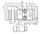
- a disc brake calliper 10 comprises a housing 12 formed with a cylinder 14.
- a piston 16 is arranged to urge brake pads 18 and 20 into pressure contact with opposite faces of a brake disc 22 when hydraulic fluid 24 is forced through inlet 26 into the cylinder 14 by a conventional brake pedal and master cylinder arrangement (not shown).
- the piston 16 comprises and inner element 28 and an outer element 30 joined by a spigot element 32.
- An annular reaction member 34 is positioned in the annular space between the inner and outer piston elements 28 and 30 and has an axial length which is less than the spacing between the inner and outer elements by a distance X equal to the required predetermined retraction distance of the piston.
- the connection between the piston 16 and the reaction member 34 is therefore a lost motion connection allowing a predetermined distance X of movement of the piston relative to the reaction member 34.
- An "0" ring friction element 36 is received in a groove in the outer surface of the reaction member and frictionally engages the inner surface of the cylinder 14.
- a coil shaped retraction spring 38 is located in a recess 40 in the reaction member 34 open towards the inner piston element 28 so that the retraction spring urges the reaction member 34 and the inner piston element 28 apart.
- reaction member and retraction spring may be formed by a plate spring device in friction contact with the cylinder 14.
Landscapes
- Engineering & Computer Science (AREA)
- General Engineering & Computer Science (AREA)
- Mechanical Engineering (AREA)
- Braking Arrangements (AREA)
Abstract
Description
- This invention relates to disc brakes and is particularly suitable for application to motor vehicle disc brakes.
- Disc braking systems currently in use in motor vehicles include a calliper with a piston working in a cylinder and arranged to urge a brake pad into pressure contact with a brake disc when hydraulic fluid is supplied to the cylinder. There is usually no return device for displacing the brake pad from the brake disc after a brake application and the brake pad remains held in contact with the disc by friction in the hydraulic actuating system unless urged back by run out of the disc or by vibration of the calliper relative to the disc.
- It is found that the frictional drag between brake pad and disc when the brakes are not actuated gives rise to an increase of average fuel consumption of the order of one per cent. In city driving on smooth roads and at relatively low speeds the percentage increase is higher.
- There have earlier been proposed means for positive retraction of the brake pad, examples of these being described in GB-A-2,097,876 and GB-A-2,036,898. Such prior solutions have resulted in an imprecise amount of retraction and this in turn caused variation in the amount of pedal movement required from one actuation to the next and different amounts of play in the pads of the different wheels.
- The present invention seeks to mitigate the above disadvantages and to permit a precise retraction of the brake pad following each actuation.
- In accordance with the present invention, there is provided a disc brake calliper including a housing formed with a cylinder, a piston for moving a brake pad into pressure contact with a brake disc and a device for positively retracting the brake pad from the disc to reduce brake drag when the brake is released, characterised in that the device for retracting the brake pad comprises a reaction member, means on the reaction member for frictionally engaging the cylinder, is movable with the piston, and is connected to the piston by a lost motion connection, and a retraction spring acting between the reaction member and the piston to retract the piston upon release of the brake, the retraction distance being precisely predetermined by the amount of lost motion in the connection between the reaction member and the piston.
- The invention will now be described further, by way of example, with reference to the accompanying drawing which is a fragmentary cross-section along the axis of the cylinder in a brake calliper embodying the invention.
- A
disc brake calliper 10 comprises ahousing 12 formed with acylinder 14. Apiston 16 is arranged to urgebrake pads brake disc 22 whenhydraulic fluid 24 is forced throughinlet 26 into thecylinder 14 by a conventional brake pedal and master cylinder arrangement (not shown). - The
piston 16 comprises andinner element 28 and anouter element 30 joined by aspigot element 32. - An
annular reaction member 34 is positioned in the annular space between the inner andouter piston elements piston 16 and thereaction member 34 is therefore a lost motion connection allowing a predetermined distance X of movement of the piston relative to thereaction member 34. - An "0"
ring friction element 36 is received in a groove in the outer surface of the reaction member and frictionally engages the inner surface of thecylinder 14. - A coil shaped
retraction spring 38 is located in arecess 40 in thereaction member 34 open towards theinner piston element 28 so that the retraction spring urges thereaction member 34 and theinner piston element 28 apart. - The force exerted by the
spring 38 on thereaction member 34 is insufficient to overcome the friction between the "O"ring 36 and thecylinder 14 but is sufficient to overcome the frictional forces affecting thepiston 16 and the hydraulic actuating system. - In operation, after the brakes are released the
retraction spring 38 moves thepiston 16 back from thedisc 22 until theouter piston element 30 contacts thereaction member 34. The distance by which thepiston 16 is moved is equal to X, the free movement of the reaction member relative to thepiston 16. - As the brake pads wear the
reaction member 34 is moved along thecylinder 14 by contact with theinner piston element 28 upon successive applications of the brakes. - Alternatively, the reaction member and retraction spring may be formed by a plate spring device in friction contact with the
cylinder 14.
Claims (4)
Applications Claiming Priority (2)
| Application Number | Priority Date | Filing Date | Title |
|---|---|---|---|
| GB08324556A GB2146716A (en) | 1983-09-14 | 1983-09-14 | Disc brake retraction device |
| GB8324556 | 1983-09-14 |
Publications (2)
| Publication Number | Publication Date |
|---|---|
| EP0140549A1 true EP0140549A1 (en) | 1985-05-08 |
| EP0140549B1 EP0140549B1 (en) | 1988-04-27 |
Family
ID=10548746
Family Applications (1)
| Application Number | Title | Priority Date | Filing Date |
|---|---|---|---|
| EP84306155A Expired EP0140549B1 (en) | 1983-09-14 | 1984-09-10 | Disc brake retraction device |
Country Status (3)
| Country | Link |
|---|---|
| EP (1) | EP0140549B1 (en) |
| DE (1) | DE3470785D1 (en) |
| GB (1) | GB2146716A (en) |
Cited By (4)
| Publication number | Priority date | Publication date | Assignee | Title |
|---|---|---|---|---|
| EP0864772A1 (en) * | 1997-03-12 | 1998-09-16 | Sumitomo Electric Industries, Ltd. | Disk brake |
| DE10012358A1 (en) * | 2000-03-14 | 2001-09-20 | Magenwirth Gmbh Co Gustav | Model racing auto hydraulic brake has self-adjusting piston |
| WO2007057929A1 (en) | 2005-11-16 | 2007-05-24 | Freni Brembo S.P.A. | Device for controlling the piston roll-back |
| WO2011077410A1 (en) * | 2009-12-24 | 2011-06-30 | Freni Brembo S.P.A. | Disc brake caliper with piston roll-back device |
Families Citing this family (2)
| Publication number | Priority date | Publication date | Assignee | Title |
|---|---|---|---|---|
| GB2315832A (en) * | 1996-07-31 | 1998-02-11 | Edward Lee White | A disc brake system |
| GB2373828A (en) * | 2001-03-05 | 2002-10-02 | Prodrive 2000 Ltd | Self-adjusting mechanism |
Citations (1)
| Publication number | Priority date | Publication date | Assignee | Title |
|---|---|---|---|---|
| GB1602068A (en) * | 1977-07-15 | 1981-11-04 | Wabco Fahrzeugbremsen Gmbh | Pressure medium operable disc brakes |
Family Cites Families (6)
| Publication number | Priority date | Publication date | Assignee | Title |
|---|---|---|---|---|
| FR1592769A (en) * | 1967-11-22 | 1970-05-19 | ||
| FR2001636A1 (en) * | 1968-02-09 | 1969-09-26 | Sumitono Electric Ind | |
| GB1327326A (en) * | 1970-11-28 | 1973-08-22 | Snc Omds Officine Meccaniche D | Self adjusting disc brakes |
| GB1600998A (en) * | 1978-05-09 | 1981-10-21 | Dormer R J | Disc brake piston retraction means |
| GB2036898B (en) * | 1978-11-06 | 1982-08-25 | Lucas Industries Ltd | Disc brakes |
| JPS57157833A (en) * | 1981-03-25 | 1982-09-29 | Sumitomo Electric Ind Ltd | Retracting mechanism of disc brake caliper |
-
1983
- 1983-09-14 GB GB08324556A patent/GB2146716A/en not_active Withdrawn
-
1984
- 1984-09-10 EP EP84306155A patent/EP0140549B1/en not_active Expired
- 1984-09-10 DE DE8484306155T patent/DE3470785D1/en not_active Expired
Patent Citations (1)
| Publication number | Priority date | Publication date | Assignee | Title |
|---|---|---|---|---|
| GB1602068A (en) * | 1977-07-15 | 1981-11-04 | Wabco Fahrzeugbremsen Gmbh | Pressure medium operable disc brakes |
Cited By (10)
| Publication number | Priority date | Publication date | Assignee | Title |
|---|---|---|---|---|
| EP0864772A1 (en) * | 1997-03-12 | 1998-09-16 | Sumitomo Electric Industries, Ltd. | Disk brake |
| US6308807B1 (en) | 1997-03-12 | 2001-10-30 | Sumitomo Electric Industrial, Ltd. | Disk brake |
| DE10012358A1 (en) * | 2000-03-14 | 2001-09-20 | Magenwirth Gmbh Co Gustav | Model racing auto hydraulic brake has self-adjusting piston |
| WO2001069102A1 (en) | 2000-03-14 | 2001-09-20 | Gustav Magenwirth Gmbh & Co. | Hydraulic brake comprising a linear adjusting piston |
| WO2007057929A1 (en) | 2005-11-16 | 2007-05-24 | Freni Brembo S.P.A. | Device for controlling the piston roll-back |
| EP2273149A1 (en) | 2005-11-16 | 2011-01-12 | Freni Brembo S.p.A. | Device for controlling the piston roll-back |
| US8225910B2 (en) | 2005-11-16 | 2012-07-24 | Freni Brembo S.P.A. | Device for controlling the piston roll-back |
| CN101351655B (en) * | 2005-11-16 | 2013-08-28 | 弗雷尼·布雷姆博有限公司 | Apparatus for controlling backspacing of piston |
| WO2011077410A1 (en) * | 2009-12-24 | 2011-06-30 | Freni Brembo S.P.A. | Disc brake caliper with piston roll-back device |
| US9285003B2 (en) | 2009-12-24 | 2016-03-15 | Freni Brembo S.P.A. | Disc brake caliper with piston roll-back device |
Also Published As
| Publication number | Publication date |
|---|---|
| DE3470785D1 (en) | 1988-06-01 |
| GB2146716A (en) | 1985-04-24 |
| EP0140549B1 (en) | 1988-04-27 |
| GB8324556D0 (en) | 1983-10-19 |
Similar Documents
| Publication | Publication Date | Title |
|---|---|---|
| US6959792B2 (en) | Retraction mechanism for disc brake assembly | |
| US4494630A (en) | Floating-caliper spot-type disc brake | |
| US4055238A (en) | Anti-squeal device in disc brake | |
| EP0068613A3 (en) | Disc bake assemblies having retraction control mechanism | |
| US4662483A (en) | Disc brake retractor | |
| US20070056812A1 (en) | Disc brake | |
| GB2102088A (en) | Disc brakes | |
| EP0140549B1 (en) | Disc brake retraction device | |
| US4386682A (en) | Piston retraction and wear compensation for low-drag disc brakes | |
| US3961690A (en) | Disc brake | |
| AU2004236396A1 (en) | Lining for disc brakes | |
| GB2099524A (en) | Disc brake | |
| JP3767073B2 (en) | Disc brake | |
| GB1410330A (en) | Spring brake actuators for disc brakes | |
| US4393963A (en) | Disc brake caliper support | |
| US4560037A (en) | Spring for a disc brake | |
| GB2036898A (en) | Disc Brakes | |
| US4285417A (en) | Floating caliper disc brake | |
| EP0236658B1 (en) | Pneumo-hydraulic converter for disc brake callipers | |
| GB1445508A (en) | Trailer disc brake and friction pad therefor | |
| GB1275241A (en) | Disk brake for vehicles | |
| GB1384517A (en) | Self-energising disc brake | |
| KR101208370B1 (en) | Disk brake | |
| US4371059A (en) | Automatic adjusting device in a disc brake | |
| EP0049179A1 (en) | Disc brake |
Legal Events
| Date | Code | Title | Description |
|---|---|---|---|
| PUAI | Public reference made under article 153(3) epc to a published international application that has entered the european phase |
Free format text: ORIGINAL CODE: 0009012 |
|
| AK | Designated contracting states |
Designated state(s): DE FR GB IT SE |
|
| 17P | Request for examination filed |
Effective date: 19851007 |
|
| 17Q | First examination report despatched |
Effective date: 19861006 |
|
| GRAA | (expected) grant |
Free format text: ORIGINAL CODE: 0009210 |
|
| AK | Designated contracting states |
Kind code of ref document: B1 Designated state(s): DE FR GB IT SE |
|
| ITF | It: translation for a ep patent filed | ||
| REF | Corresponds to: |
Ref document number: 3470785 Country of ref document: DE Date of ref document: 19880601 |
|
| ET | Fr: translation filed | ||
| PG25 | Lapsed in a contracting state [announced via postgrant information from national office to epo] |
Ref country code: DE Effective date: 19880728 |
|
| PG25 | Lapsed in a contracting state [announced via postgrant information from national office to epo] |
Ref country code: GB Effective date: 19880910 |
|
| PG25 | Lapsed in a contracting state [announced via postgrant information from national office to epo] |
Ref country code: SE Effective date: 19880911 |
|
| PLBE | No opposition filed within time limit |
Free format text: ORIGINAL CODE: 0009261 |
|
| STAA | Information on the status of an ep patent application or granted ep patent |
Free format text: STATUS: NO OPPOSITION FILED WITHIN TIME LIMIT |
|
| 26N | No opposition filed | ||
| GBPC | Gb: european patent ceased through non-payment of renewal fee | ||
| PG25 | Lapsed in a contracting state [announced via postgrant information from national office to epo] |
Ref country code: FR Effective date: 19900531 |
|
| REG | Reference to a national code |
Ref country code: FR Ref legal event code: ST |
|
| EUG | Se: european patent has lapsed |
Ref document number: 84306155.7 Effective date: 19890712 |