EP0139819A2 - Support for a hand-held drilling machine - Google Patents
Support for a hand-held drilling machine Download PDFInfo
- Publication number
- EP0139819A2 EP0139819A2 EP84104147A EP84104147A EP0139819A2 EP 0139819 A2 EP0139819 A2 EP 0139819A2 EP 84104147 A EP84104147 A EP 84104147A EP 84104147 A EP84104147 A EP 84104147A EP 0139819 A2 EP0139819 A2 EP 0139819A2
- Authority
- EP
- European Patent Office
- Prior art keywords
- column
- work stand
- bearing
- base plate
- stand according
- Prior art date
- Legal status (The legal status is an assumption and is not a legal conclusion. Google has not performed a legal analysis and makes no representation as to the accuracy of the status listed.)
- Withdrawn
Links
- 238000005553 drilling Methods 0.000 title description 4
- 238000003860 storage Methods 0.000 claims description 3
- 241000237942 Conidae Species 0.000 claims 1
- 238000004519 manufacturing process Methods 0.000 abstract description 5
- 238000010276 construction Methods 0.000 description 4
- 238000003801 milling Methods 0.000 description 4
- 238000006073 displacement reaction Methods 0.000 description 2
- 238000000034 method Methods 0.000 description 2
- NJPPVKZQTLUDBO-UHFFFAOYSA-N novaluron Chemical compound C1=C(Cl)C(OC(F)(F)C(OC(F)(F)F)F)=CC=C1NC(=O)NC(=O)C1=C(F)C=CC=C1F NJPPVKZQTLUDBO-UHFFFAOYSA-N 0.000 description 2
- 229910001018 Cast iron Inorganic materials 0.000 description 1
- 238000001514 detection method Methods 0.000 description 1
- 238000003754 machining Methods 0.000 description 1
Images


Classifications
-
- B—PERFORMING OPERATIONS; TRANSPORTING
- B23—MACHINE TOOLS; METAL-WORKING NOT OTHERWISE PROVIDED FOR
- B23Q—DETAILS, COMPONENTS, OR ACCESSORIES FOR MACHINE TOOLS, e.g. ARRANGEMENTS FOR COPYING OR CONTROLLING; MACHINE TOOLS IN GENERAL CHARACTERISED BY THE CONSTRUCTION OF PARTICULAR DETAILS OR COMPONENTS; COMBINATIONS OR ASSOCIATIONS OF METAL-WORKING MACHINES, NOT DIRECTED TO A PARTICULAR RESULT
- B23Q1/00—Members which are comprised in the general build-up of a form of machine, particularly relatively large fixed members
- B23Q1/25—Movable or adjustable work or tool supports
- B23Q1/44—Movable or adjustable work or tool supports using particular mechanisms
- B23Q1/48—Movable or adjustable work or tool supports using particular mechanisms with sliding pairs and rotating pairs
-
- B—PERFORMING OPERATIONS; TRANSPORTING
- B23—MACHINE TOOLS; METAL-WORKING NOT OTHERWISE PROVIDED FOR
- B23Q—DETAILS, COMPONENTS, OR ACCESSORIES FOR MACHINE TOOLS, e.g. ARRANGEMENTS FOR COPYING OR CONTROLLING; MACHINE TOOLS IN GENERAL CHARACTERISED BY THE CONSTRUCTION OF PARTICULAR DETAILS OR COMPONENTS; COMBINATIONS OR ASSOCIATIONS OF METAL-WORKING MACHINES, NOT DIRECTED TO A PARTICULAR RESULT
- B23Q1/00—Members which are comprised in the general build-up of a form of machine, particularly relatively large fixed members
- B23Q1/25—Movable or adjustable work or tool supports
- B23Q1/26—Movable or adjustable work or tool supports characterised by constructional features relating to the co-operation of relatively movable members; Means for preventing relative movement of such members
- B23Q1/28—Means for securing sliding members in any desired position
-
- B—PERFORMING OPERATIONS; TRANSPORTING
- B23—MACHINE TOOLS; METAL-WORKING NOT OTHERWISE PROVIDED FOR
- B23Q—DETAILS, COMPONENTS, OR ACCESSORIES FOR MACHINE TOOLS, e.g. ARRANGEMENTS FOR COPYING OR CONTROLLING; MACHINE TOOLS IN GENERAL CHARACTERISED BY THE CONSTRUCTION OF PARTICULAR DETAILS OR COMPONENTS; COMBINATIONS OR ASSOCIATIONS OF METAL-WORKING MACHINES, NOT DIRECTED TO A PARTICULAR RESULT
- B23Q1/00—Members which are comprised in the general build-up of a form of machine, particularly relatively large fixed members
- B23Q1/25—Movable or adjustable work or tool supports
- B23Q1/44—Movable or adjustable work or tool supports using particular mechanisms
- B23Q1/50—Movable or adjustable work or tool supports using particular mechanisms with rotating pairs only, the rotating pairs being the first two elements of the mechanism
- B23Q1/52—Movable or adjustable work or tool supports using particular mechanisms with rotating pairs only, the rotating pairs being the first two elements of the mechanism a single rotating pair
-
- B—PERFORMING OPERATIONS; TRANSPORTING
- B25—HAND TOOLS; PORTABLE POWER-DRIVEN TOOLS; MANIPULATORS
- B25H—WORKSHOP EQUIPMENT, e.g. FOR MARKING-OUT WORK; STORAGE MEANS FOR WORKSHOPS
- B25H1/00—Work benches; Portable stands or supports for positioning portable tools or work to be operated on thereby
- B25H1/0021—Stands, supports or guiding devices for positioning portable tools or for securing them to the work
- B25H1/0042—Stands
-
- Y—GENERAL TAGGING OF NEW TECHNOLOGICAL DEVELOPMENTS; GENERAL TAGGING OF CROSS-SECTIONAL TECHNOLOGIES SPANNING OVER SEVERAL SECTIONS OF THE IPC; TECHNICAL SUBJECTS COVERED BY FORMER USPC CROSS-REFERENCE ART COLLECTIONS [XRACs] AND DIGESTS
- Y10—TECHNICAL SUBJECTS COVERED BY FORMER USPC
- Y10S—TECHNICAL SUBJECTS COVERED BY FORMER USPC CROSS-REFERENCE ART COLLECTIONS [XRACs] AND DIGESTS
- Y10S408/00—Cutting by use of rotating axially moving tool
- Y10S408/712—Drill press adapted to use portable hand drill
-
- Y—GENERAL TAGGING OF NEW TECHNOLOGICAL DEVELOPMENTS; GENERAL TAGGING OF CROSS-SECTIONAL TECHNOLOGIES SPANNING OVER SEVERAL SECTIONS OF THE IPC; TECHNICAL SUBJECTS COVERED BY FORMER USPC CROSS-REFERENCE ART COLLECTIONS [XRACs] AND DIGESTS
- Y10—TECHNICAL SUBJECTS COVERED BY FORMER USPC
- Y10T—TECHNICAL SUBJECTS COVERED BY FORMER US CLASSIFICATION
- Y10T408/00—Cutting by use of rotating axially moving tool
- Y10T408/55—Cutting by use of rotating axially moving tool with work-engaging structure other than Tool or tool-support
- Y10T408/561—Having tool-opposing, work-engaging surface
- Y10T408/5614—Angularly adjustable surface
- Y10T408/5616—Adjustable about axis that is parallel to tool-axis
-
- Y—GENERAL TAGGING OF NEW TECHNOLOGICAL DEVELOPMENTS; GENERAL TAGGING OF CROSS-SECTIONAL TECHNOLOGIES SPANNING OVER SEVERAL SECTIONS OF THE IPC; TECHNICAL SUBJECTS COVERED BY FORMER USPC CROSS-REFERENCE ART COLLECTIONS [XRACs] AND DIGESTS
- Y10—TECHNICAL SUBJECTS COVERED BY FORMER USPC
- Y10T—TECHNICAL SUBJECTS COVERED BY FORMER US CLASSIFICATION
- Y10T408/00—Cutting by use of rotating axially moving tool
- Y10T408/65—Means to drive tool
- Y10T408/675—Means to drive tool including means to move Tool along tool-axis
- Y10T408/6779—Rack and pinion
-
- Y—GENERAL TAGGING OF NEW TECHNOLOGICAL DEVELOPMENTS; GENERAL TAGGING OF CROSS-SECTIONAL TECHNOLOGIES SPANNING OVER SEVERAL SECTIONS OF THE IPC; TECHNICAL SUBJECTS COVERED BY FORMER USPC CROSS-REFERENCE ART COLLECTIONS [XRACs] AND DIGESTS
- Y10—TECHNICAL SUBJECTS COVERED BY FORMER USPC
- Y10T—TECHNICAL SUBJECTS COVERED BY FORMER US CLASSIFICATION
- Y10T408/00—Cutting by use of rotating axially moving tool
- Y10T408/83—Tool-support with means to move Tool relative to tool-support
- Y10T408/85—Tool-support with means to move Tool relative to tool-support to move radially
- Y10T408/858—Moving means including wedge, screw or cam
- Y10T408/8588—Axially slidable moving-means
- Y10T408/85896—Annular wedge-collar
Definitions
- the invention relates to a work stand for a hand drill with a height-adjustable bearing block on a pillar, a guide plate pivotally mounted on the bearing block about a horizontal axis, a lifting slide displaceable in a prismatic guideway of the guide plate and a machine holder mounted pivotably on the lifting slide about a horizontal axis.
- a pivoting device in which a central pin or the like is comprised of two half cylinder shells which can be pressed together by screws and thus clamped onto the pin .
- a continuous pivoting movement up to a full rotation is possible.
- the half-cylinder shells must have a relatively large length, which would lead to an excessive size in the case of a work stand with two horizontal pivot axes.
- the invention has for its object to provide a generic work stand that is infinitely adjustable up to a full rotation about both axes of rotation, which can accommodate large torques in the determined state, which has a small size and is easy to manufacture.
- the guide plate and the machine holder are each mounted with a truncated cone-shaped, widening towards the outside in associated conical pivot bearings on the bearing block or lifting slide.
- Such one conical rotary guide is infinitely adjustable at any angle.
- the decisive advantage is that the wedge action of the conical bearing surfaces allows high clamping moments to be achieved even with a small overall length.
- the conical bearing guide ensures that the axis of rotation is centered, so that no additional centering devices such as guide webs or the like need be provided. The two swivel devices can therefore be produced with a comparatively low production cost.
- the bearing block and the lifting slide can each consist of two housing parts which are divided parallel to their direction of displacement and to the axis of the conical pivot bearing and each clamped together by enclosing one of the bearing pins, each with a half conical shell.
- the bearing block and the lifting slide are constructed from two housing parts, the assembly of the truncated cone-shaped bearing pins, which become wider towards the outside, is completely unproblematic.
- the conical shells of the two housing parts can be operationally tightened or loosened by the one or more tensioning screws which pass closely past the conical shells.
- the clamping forces between the two housing parts can be varied continuously in a convenient manner, ie. H.
- the trunnions can be tightened or loosened. Due to the high clamping torques, short adjustment paths are sufficient to achieve a sufficient tightening of the bearing journals.
- the bearing journal of the machine holder can carry at its free end a coaxial worm wheel, in which an adjusting worm mounted in the lifting slide engages. After releasing the clamping, the machine holder can thus be rotated in a particularly sensitive manner with respect to the lifting slide, and even heavier machines do not need to be pulled out of the machine holder during the adjustment process.
- the frustoconical bearing journal of the guide plate can be screwed to the guide plate by a central axial screw, the actuating end of the screw can be accessed from the side for the purpose of attaching a turning tool or turning handle, and the bearing journal can be operated by operating the screw in the Pivots can be clamped or loosened.
- the bearing journals are not clamped by changing the pivot bearing, but rather by an axial displacement of the bearing journal.
- the base plate has a working surface lying in front of and next to the column, which merge into one another.
- the Base plate should be approximately square and the column should be arranged off-center in a 2: 1 aspect ratio.
- the base plate can also have an angular plan and the column can be arranged on the inner corner.
- the projection distance between the column and the center of the machine holder advantageously corresponds to approximately half the side length of the base plate.
- the base plate has a molded, longitudinally slotted, cylindrical receiving sleeve, within which the column can be rotated during operation and the halves of which are designed as clamping jaws.
- the base plate can be close to the column with one or more receiving holes for Allen keys and with grooves and / or webs for roll-safe storage of drills or the like.
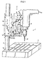
- Fig. 1 shows a work stand 1, which consists of a base plate 2, a column 3 and an adjusting head 4.
- the adjusting head 4 is composed in detail of a bearing block 5, a guide plate 6, a lifting slide 7 and a machine holder 8.
- a hand drill 9 can be clamped.
- the bearing block 5 can be pushed up and down on the column 3 in the vertical direction 10, and can be pivoted about it according to the arrows 11.
- the determination on the column 3 takes place via the clamping screws 12, which clamp the two housing halves 13, 14 of the bearing block 5 against each other; cf. FIG. 2.
- the guide plate 6 is provided with a truncated cone-shaped bearing pin 15 which widens towards the outside and which is mounted in a pivot bearing 16 on the bearing block 5.
- the bearing pin 15 is screwed to the guide plate 6 with the aid of two screws 17 and nuts 18, the nuts 18 being guided in guide slots 19 and thus prevented from rotating.
- the separate design of guide plate 6 and bearing pin 15 facilitates the manufacture and assembly of these parts.
- the bearing pin 15 in the pivot bearing 16 is fixed by tightening the clamping screws 20 and 21, as a result of which the housing halves 13, 14 and thus the half conical shells 22, 23 are pressed against one another.
- the bearing journal can be determined only by actuating the tensioning screw 21 when selecting suitable manufacturing tolerances.
- the guide plate 6 has a prismatic guide track 25, along which the lifting carriage 7 can be displaced in the direction 26. This movement of the lifting carriage 7 causes the tool 27 to be advanced and can be controlled via a toothed rack 28, a pinion 29 and a control lever 30; compare FIGS. 1 and 2.
- the lifting slide 7 is also made of two halves 31, 32 which can be pressed together by means of clamping screws 33.
- the housing halves 31, 32 each have a half conical shell 34, 35, which together form a rotary bearing 36 for the frustoconical bearing journal 37 of the machine holder 8.
- the bearing pin 37 of the machine holder 8 carries at its free end a coaxial worm wheel 38, into which an adjusting screw 39 mounted in the lifting slide 7 engages.
- the adjustment screw. 39 is in turn via the rotary lever 40 operated.
- the bearing pin 37 is fixed in the pivot bearing 36 by means of the clamping screw 41.
- the machine 9 can be pivoted in a vertical plane in two ways: on the one hand, a rotation around the bearing journal 15 in the direction of the arrows 42 is possible, which results in a change in the feed direction 26. On the other hand, a rotation of the bearing pin 37 according to the arrows 43 causes the machine 9 to pivot relative to the feed direction 26.
- a rotation of the bearing pin 37 according to the arrows 43 causes the machine 9 to pivot relative to the feed direction 26.
- the tool 27 can come into positions, in particular during milling work, which can result in a high moment load on the rotary bearings 16, 36, but which are safely absorbed in the construction according to the invention.
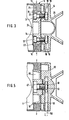
- Fig. 4 shows a work stand 44, the base plate 2, column 3, bearing block 4, lifting carriage 7 and machine holder -8 are identical to the embodiment of FIG. 1. Only the guide plate 45 and the frustoconical bearing journal 46 are new.
- the bearing journal 46 is, as shown in more detail in FIG. 5, by a central axial screw 47 the guide plate 45 screwed. At the actuating end 48 of the screw 47, a nut 49 is placed, which can be actuated via a turning tool or a turning handle 50 indicated by dash-dotted lines.
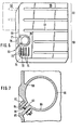
- the base plate 55 of the work stand which is made of cast iron, is provided with an integrally formed receiving sleeve 56 for the column 3, which is arranged off-center at the rear edge 58 of the base plate with a side division ratio of approximately 2: 1.
- the overall approximately square base plate 55 comprises a working surface 59 which extends as usual in front of the column and an additional working surface 60 lying next to it and extending as far as the column, in which, as usual, slots 61 are arranged for attaching workpiece clamping elements or the like.
- the secondary work surface can also extend beyond the rear edge 58 in accordance with a modified embodiment, so that a base plate 62 of an angular plan results, on the inner corner of which the column lies.
- the receiving sleeve 56 for the column is provided with a longitudinal slot 63, the slot edges being provided with angled flanges 64, 65, which can be clamped together by a screw 66 with an Allen head 67, so that the column for operational adjustment between the jaws 68 and 69 of the Sleeve 56 can be tightened or loosened.
- a scale 70 surrounding the receiving opening for the column is provided on the base plate. Furthermore, the base plate in the vicinity of the column is provided with receiving holes 71, 72 for Allen keys and with raised webs 73 and grooves 74 therebetween for the roll-proof storage of drills or the like.
Abstract
Ein Arbeitsständer (1) für eine Handbohrmaschine (9) mit einem auf einer Säule (3) höhenverstellbaren Lagerbock (5), einer um eine horizontale Achse schwenkbar am Lagerbock (5) gelagerten Führungsplatte (6), einem in einer prismatischen Führungsbahn (25) der Führungsplatte (6) verschiebbaren Hubschlitten (7) und einem um eine horizontale Achse schwenkbar am Hubschlitten (7) gelagerten Maschinenhalter (8) soll um beide Drehachsen bis zu einer vollen Umdrehung stufenlos verstellbar sein, in festgestelltem Zustand große Drehmomente aufnehmen können, eine geringe Baugröße aufweisen und einfach herstellbar sein. Zur Lösung dieser Aufgabe ist erfindungsgemäß vorgesehen, daß die Führungsplatte (6) und der Maschinenhalter (8) jeweils mit einem kegelstumpffömigen, nach außen hin breiter werdenden Lagerzapfen (15, 37) in zugeordneten, konischen Drehlagern (16, 36) am Lagerbock (5) bzw. Hubschlitten (7) gelagert sind.A work stand (1) for a hand drill (9) with a bearing block (5) adjustable in height on a column (3), a guide plate (6) mounted on the bearing block (5) so as to be pivotable about a horizontal axis, and a in a prismatic guideway (25) The guide plate (6) displaceable lifting carriage (7) and a machine holder (8) which can be pivoted about a horizontal axis on the lifting carriage (7) should be infinitely adjustable around both axes of rotation up to a full rotation, and can take up high torques in the determined state, a small one Have size and be easy to manufacture. To achieve this object, the invention provides that the guide plate (6) and the machine holder (8) each have a truncated cone-shaped bearing pin (15, 37) widening towards the outside in associated conical pivot bearings (16, 36) on the bearing block (5 ) or lifting carriage (7) are stored.
Description
Die Erfindung betrifft einen Arbeitsständer für eine Handbohrmaschine mit einem auf einer Säule höhenverstellbaren Lagerbock, einer um eine horizontale Achse schwenkbar am Lagerbock gelagerten Führungsplatte, einem in einer prismatischen Führungsbahn der Führungsplatte verschiebbaren Hubschlitten und einem um eine horizontale Achse schwenkbar am Hubschlitten gelagerten Maschinenhalter.The invention relates to a work stand for a hand drill with a height-adjustable bearing block on a pillar, a guide plate pivotally mounted on the bearing block about a horizontal axis, a lifting slide displaceable in a prismatic guideway of the guide plate and a machine holder mounted pivotably on the lifting slide about a horizontal axis.
Derartige Arbeitsständer, die neben einer senkrechten Verstellbarkeit auch eine zweifache Schwenkbarkeit aufweisen, erlauben eine Vielzahl verschiedener Arbeitsgänge. Außer dem üblichen senkrechten ist auch ein waagerechtes oder schräges Bohren sowie ein waagerechtes, senkrechtes oder schräges Fräsen möglich. Vor allem bei Fräsarbeiten können dabei an den beiden Schwenkachsen große Drehmomente auftreten,.die durch besonders stabile Feststelleinrichtungen aufgefangen werden müssen.Work stands of this type, which, in addition to being vertically adjustable, can also be swiveled twice, permit a large number of different work steps. In addition to the usual vertical, there is also a scale right or angled drilling as well as horizontal, vertical or oblique milling possible. Especially when milling, large torques can occur on the two swivel axes, which must be absorbed by particularly stable locking devices.
Durch die DE-PS 30 40 651 ist ein Arbeitsständer bekannt, bei dem zur Feststellung einer Drehung um eine horizontale Achse zwei vertikale Kreisflächen mit Stirnverzahnungen aufeinandergepreßt werden. Diese Einrichtung erlaubt ein beliebiges Verschwenken bis zu einer vollen Umdrehung. Neben der Stirnverzahnung muß jedoch ein gesondertes Führungslager zur Zentrierung der Drehachse vorgesehen sein; außerdem ist nur eine stufenweise Verstellung möglich.From DE-PS 30 40 651 a work stand is known in which two vertical circular surfaces with spur gears are pressed together to determine a rotation about a horizontal axis. This device allows any pivoting up to a full revolution. In addition to the spur toothing, however, a separate guide bearing must be provided for centering the axis of rotation; in addition, only a gradual adjustment is possible.
Weiterhin sind Arbeitsständer bekannt, bei denen zwei kreisförmige, glatte Stirnflächen mit Hilfe von Schrauben aufeinandergepreßt werden, welche in bogenförmigen Führungsschlitzen laufen. In diesem Falle ist zwar eine kontinuierliche Schwenkbewegung möglich, doch können die Führungsschlitze aus Festigkeitsgründen sich allenfalls über einen Bogen von etwa 90° erstrecken; d. h. der Schwenkwinkel ist stark begrenzt. Um ein ausreichendes Feststellmoment zu erzielen, müssen weiterhin die aufeinandergepreßten Flächen einen großen Durchmesser aufweisen.Furthermore, work stands are known in which two circular, smooth end faces are pressed together with the aid of screws, which run in arcuate guide slots. In this case, a continuous pivoting movement is possible, but the guide slots can at best extend over an arc of approximately 90 ° for reasons of strength; d. H. the swivel angle is very limited. In order to achieve a sufficient locking torque, the pressed surfaces must also have a large diameter.
Durch die DE-PS 30 40 651 ist schließlich - hier allerdings in Bezug auf die Säule - eine Schwenkeinrichtung bekannt, bei der ein zentraler Zapfen oder dgl. von zwei halben Zylinderschalen umfaßt wird, die durch Schrauben aneinandergepreßt und somit auf dem Zapfen festgeklemmt werden können. Bei dieser Ausführungsform ist eine kontinuierliche Schwenkbewegung bis hin zu einer vollen Umdrehung möglich. Zur Erzielung von ausreichenden Klemmkräften müssen die Halbzylinderschalen jedoch eine relativ große Länge aufweisen, was im Falle eines Arbeitsständers mit zwei horizontalen Schwenkachsen zu einer übermäßigen Baugröße führen würde.From DE-PS 30 40 651 finally - but here in relation to the column - a pivoting device is known in which a central pin or the like is comprised of two half cylinder shells which can be pressed together by screws and thus clamped onto the pin . In this embodiment, a continuous pivoting movement up to a full rotation is possible. To achieve sufficient clamping forces, however, the half-cylinder shells must have a relatively large length, which would lead to an excessive size in the case of a work stand with two horizontal pivot axes.
Der Erfindung liegt die Aufgabe zugrunde, einen gattungsgemäßen Arbeitsständer zu schaffen, der um beide Drehachsen bis zu einer vollen Umdrehung stufenlos verstellbar ist, der in festgestelltem Zustand große Drehmomente aufnehmen kann, der eine geringe Baugröße aufweist und der einfach herstellbar ist.The invention has for its object to provide a generic work stand that is infinitely adjustable up to a full rotation about both axes of rotation, which can accommodate large torques in the determined state, which has a small size and is easy to manufacture.
Diese Aufgabe ist erfindungsgemäß dadurch gelöst, daß die Führungsplatte und der Maschinenhalter jeweils mit einem kegelstumpfförmigen, nach außen hin breiter werdenden Lsgerzapfen in zugeordneten, konischen Drehlagern am Lagerbock bzw. Hubschlitten gelagert sind. Eine derartige konische Drehführung ist in beliebigen Winkeln stufenlos verstellbar. Im Hinblick auf die Feststellung der Drehung liegt der entscheidende Vorteil darin, daß sich durch die Keilwirkung der konischen Lagerflächen schon bei einer geringen Baulänge hohe Klemmomente erzielen lassen. Schließlich sorgtdie konische Lagerführung für eine Zentrierung der Drehachse, so daß keine zusätzlichen Zentriereinrichtungen wie Führungsstege oder dgl. vorgesehen sein müssen. Die beiden Schwenkvorrichtungen sind daher mit einem vergleichsweise geringen Fertigungsaufwand herstellbar.This object is achieved in that the guide plate and the machine holder are each mounted with a truncated cone-shaped, widening towards the outside in associated conical pivot bearings on the bearing block or lifting slide. Such one conical rotary guide is infinitely adjustable at any angle. With regard to the detection of the rotation, the decisive advantage is that the wedge action of the conical bearing surfaces allows high clamping moments to be achieved even with a small overall length. Finally, the conical bearing guide ensures that the axis of rotation is centered, so that no additional centering devices such as guide webs or the like need be provided. The two swivel devices can therefore be produced with a comparatively low production cost.
Der Erfindung zufolge können der Lagerbock und der Hubschlitten jeweils aus zwei parallel zu ihrer Verschieberichtung und zur Achse des konischen Drehlagers geteilten und unter Einfassung jeweils eines der Lagerzapfen zusammengespannten Gehäuseteilen mit jeweils einer halben Konusschale bestehen. Bei einem Aufbau des Lagerbocks und des Hubschlittens aus zwei Gehäuseteilen ist die Montage der kegelstumpfförmigen, nach außen hin breiter werdenden Lagerzapfen völlig unproblematisch. Durch eine Variation der Spannkräfte zwischen den beiden Gehäuseteilen besteht zudem die Möglichkeit, das Spiel der konischen Drehlager zu variieren und damit eine Feststellung bzw, ein Lösen der Lagerzapfen zu bewirken.According to the invention, the bearing block and the lifting slide can each consist of two housing parts which are divided parallel to their direction of displacement and to the axis of the conical pivot bearing and each clamped together by enclosing one of the bearing pins, each with a half conical shell. When the bearing block and the lifting slide are constructed from two housing parts, the assembly of the truncated cone-shaped bearing pins, which become wider towards the outside, is completely unproblematic. By varying the clamping forces between the two housing parts, there is also the possibility of varying the play of the conical pivot bearings and thus of establishing or loosening the bearing pins.
Nach einer bevorzugten Ausführungsform der Erfindung können die Konusschalen der beiden Gehäuseteile durch eine oder mehrere, eng an den Konusschalen vorbeiführende Spannschrauben betriebsmäßig an dem Lagerzapfen festspannbar bzw, von diesem lockerbar sein. Durch derartige Spannschrauben sind die Spannkräfte zwischen den beiden Gehäuseteilen in bequemer Weise stufenlos variierbar, d. h. durch eine Veränderung des radialen Spiels der konischen Drehlager können die Lagerzapfen festgespannt bzw, gelockert werden. Aufgrund der hohen Klemmomente genügen dabei geringe Verstellwege, um eine ausreichende Festspannung der Lagerzapfen zu erreichen.According to a preferred embodiment of the invention, the conical shells of the two housing parts can be operationally tightened or loosened by the one or more tensioning screws which pass closely past the conical shells. By means of such clamping screws, the clamping forces between the two housing parts can be varied continuously in a convenient manner, ie. H. By changing the radial play of the conical pivot bearings, the trunnions can be tightened or loosened. Due to the high clamping torques, short adjustment paths are sufficient to achieve a sufficient tightening of the bearing journals.
In Ausgestaltung der Erfindung kann der Lagerzapfen des Maschinenhalters an seinem freien Ende ein koaxiales Schneckenrad tragen, in das eine im Hubschlitten gelagerte Verstellschnecke eingreift. Nach dem Lösen der Festklemmung kann damit der Maschinenhalter gegenüber dem Hubschlitten in besonders feinfühliger Weise verdreht werden, wobei auch schwerere Maschinen beim Verstellvorgang nicht aus dem Maschinenhalter herausgezogen zu werden brauchen.In an embodiment of the invention, the bearing journal of the machine holder can carry at its free end a coaxial worm wheel, in which an adjusting worm mounted in the lifting slide engages. After releasing the clamping, the machine holder can thus be rotated in a particularly sensitive manner with respect to the lifting slide, and even heavier machines do not need to be pulled out of the machine holder during the adjustment process.
Da aber bei Schneckenrädern stets ein gewisses Flankenspiel vorhanden ist, muß auch hier der Lagerzapfen des Maschinenhalters während eines Arbeitsvorgangs festgestellt werden. Die vorbeschriebene Verstellmöglichkeit über ein Schneckenrad und eine Versasllschneci ist nicht zwingend erforderlich, da nach leichtem Lösen der Lagerzapfen-Festklemmung der gesamte Maschinenhalter auch von Hand in die gewünschte neue Position geschwenkt werden kann.However, since there is always a certain amount of backlash in worm gears, the bearing journal of the machine holder must also be ascertained during a work process. The above-described adjustment option via a worm wheel and a Versasllschneci is not mandatory required, since after loosening the trunnion clamp the entire machine holder can also be swiveled into the desired new position by hand.
Nach einer weiteren Ausführungsform der Erfindung kann der kegelstumpfförmige Lagerzapfen der Führungsplatte durch eine zentrale axiale Schraube an die Führungsplatte angeschraubt sein, kann das Betätigungsende der Schraube von der Seite her zwecks Anbringung eines Drehwerkzeuges oder Drehgriffes zugänglich sein und kann der Lagerzapfen durch Betätigen der Schraube betriebsmäßig im Drehlager festspannbar oder lockerbar sein. Bei dieser Ausführungsform der Erfindung erfolgt das Festspannen der Lagerzapfen nicht durch eine Veränderung des Drehlagers, sondern durch eine axiale Verschiebung des Lagerzapfens. Der besondere Vorteil dieser Konstruktion liegt darin, daß zur Feststellung des Lagerzapfens nur eine einzige Schraube betätigt zu werden braucht, d. h. diese Bauform ist besonders anwenderfreundlich.According to a further embodiment of the invention, the frustoconical bearing journal of the guide plate can be screwed to the guide plate by a central axial screw, the actuating end of the screw can be accessed from the side for the purpose of attaching a turning tool or turning handle, and the bearing journal can be operated by operating the screw in the Pivots can be clamped or loosened. In this embodiment of the invention, the bearing journals are not clamped by changing the pivot bearing, but rather by an axial displacement of the bearing journal. The particular advantage of this construction lies in the fact that only a single screw needs to be actuated to fix the bearing journal, i. H. this design is particularly user-friendly.
Bei einem Arbeitsständer, bei dem die Säule am hinteren Rand der Grundplatte angeordnet ist, ist der Erfindung zufolge bevorzugt vorgesehen, daß die Grundplatte eine vor und eine neben der Säule liegende Arbeitsfläche aufweist, die ineinanderübergehen. Zu diesem Zweck kann die Grundplatte etwa quadratisch sein und die Säule etwa im Seitenteilungsverhältnis 2:1 außermittig angeordnet sein. Alternativ kann aber auch die Grundplatte einen winkelförmigen Grundriß aufweisen und die Säule an der inneren Winkelecke angeordnet sein. Der Projektions-Abstand zwischen Säule und Zentrum des Maschinenhalters entspricht dabei vorteilhafterweise etwa der halben Seitenlänge der Grundplatte. Bei diesem Aufbau des Arbeitsständers ist der Tateache Rechnung getragen, daß mit dem Arbeitsständer nach der Erfindung nicht nur einfache Bohr-, sondern auch Fräsarbeiten verschiedenster Art ausgeführt werden können. Die Größe der.Arbeitsplatte und die Anordnung der Säule kann dabei völlig auf die Erfordernisse einer günstigen Werkstückbearbeitung ausgerichtet sein, da auf die Größe der von dem Arbeitsständer aufzunehmenden Drehmomente keine Rücksicht genommen zu werden braucht.In a work stand in which the column is arranged at the rear edge of the base plate, it is preferably provided according to the invention that the base plate has a working surface lying in front of and next to the column, which merge into one another. For this purpose, the Base plate should be approximately square and the column should be arranged off-center in a 2: 1 aspect ratio. Alternatively, however, the base plate can also have an angular plan and the column can be arranged on the inner corner. The projection distance between the column and the center of the machine holder advantageously corresponds to approximately half the side length of the base plate. With this construction of the work stand, the Tateache takes into account that with the work stand according to the invention, not only simple drilling but also milling work of all kinds can be carried out. The size of the worktop and the arrangement of the column can be completely geared to the requirements of inexpensive workpiece machining, since the size of the torques to be absorbed by the work stand need not be taken into account.
In Ausgestaltung der Erfindung kann ferner vorgesehen werden, daß die Grundplatte eine angeformte, längsgeschlitzte, zylindrische Aufnahmehülse aufweist, innerhalb der die Säule betriebsmäßig dreheinstellbar ist und deren Hälften als Klemmbacken ausgebildet sind.In an embodiment of the invention it can further be provided that the base plate has a molded, longitudinally slotted, cylindrical receiving sleeve, within which the column can be rotated during operation and the halves of which are designed as clamping jaws.
Schließlich kann der Erfindung zufolge die Grundplatte nahe der Säule mit einem oder mit mehreren Aufnahmelöchern für Imbus-Schlüssel und mit Rillen und/oder Stegen zur abrollsicheren Ablage von Bohrern oder dgl. versehen sein.Finally, according to the invention, the base plate can be close to the column with one or more receiving holes for Allen keys and with grooves and / or webs for roll-safe storage of drills or the like.
Die Erfindung wird im folgenden anhand der Zeichnung näher beschrieben. In der Zeichnung zeigen :
- Fig. 1 einen Arbeitsständer mit eingespannter Handbohrmaschine in Seitenansicht,
- Fig. 2 den Stellkopf des Arbeitsständers gemäß einer Blickrichtung II in Fig. 1,
- Fig. 3 einen Schnitt durch Lagerbock und Führungs- platte des Arbeitsständers entlang einer Linie III-III in Fig. 1,
- Fig. 4 einen Arbeitsständer mit axialer Verschraubung des Lagerzapfens der Führungsplatte in Seitenansicht,
- Fig. 5 einen Schnitt durch Lagerbock und Führungsplatte des Arbeitsständers entlang einer Linie V-V in Fig. 4,
- Fig. 6 in Draufsicht eine weitere Ausführungsform der Grundplatte des Arbeitsständers und
- Fig. 7 einen Horizontalschnitt durch die Grundplatte nach Fig. 6 im Bereich der Säulenlagerung.
- 1 shows a work stand with a clamped hand drill in side view,
- 2 the adjusting head of the work stand according to a viewing direction II in FIG. 1,
- Figure 3 is a section through the bearing block and guide -. Stand plate of the work along a line III-III in Figure 1.
- 4 shows a work stand with axial screwing of the bearing pin of the guide plate in a side view,
- 5 shows a section through the bearing block and guide plate of the work stand along a line VV in FIG. 4,
- Fig. 6 in plan view a further embodiment of the base plate of the work stand and
- Fig. 7 is a horizontal section through the base plate of FIG. 6 in the area of the column bearing.
Fig. 1 zeigt einen Arbeitsständer 1, welcher aus einer Grundplatte 2, einer Säule 3 sowie einem Stellkopf 4 besteht. Der Stellkopf 4 setzt sich im einzelnen aus einem Lagerbock 5, einer Führungsplatte 6, einem Hubschlitten 7 und einem Maschinenhalter 8 zusammen. In den Maschinenhalter 8 kann z. B. eine Handbohrmaschine 9 eingespannt werden. Der Lagerbock 5 kann auf der Säule 3 in vertikaler Richtung 10 auf- und ab geschoben werden, sowie gemäß den Pfeilen 11 um diese geschwenkt werden. Die Feststellung auf der Säule 3 erfolgt dabei über die Spannschrauben 12, welche die beiden Gehäusehälften 13, 14 des Lagerbocks 5 gegeneinanderspannen; vergleiche Fig. 2. Die Führungsplatte 6 ist mit einem kegelstumpfförmigen, nach außen hin breiter werdenden Lagerzapfen 15 versehen, welcher in einem Drehlager 16 am Lagerbock 5 gelagert ist. Der Lagerzapfen 15 ist dabei mit Hilfe von zwei Schrauben 17 sowie Muttern 18 mit der Führungsplatte 6 verschraubt, wobei die Muttern 18 in Führungsschlitzen 19 geführt und damit am Verdrehen gehindert werden. Die getrennte Ausführung von Führungsplatte 6 und Lagerzapfen 15 erleichtert Fertigung und Montage dieser Teile. In der Ausführung gemäß den Fig. 1 und 3 erfolgt die Feststellung des Lagerzapfens 15 im Drehlager 16 durch ein Anziehen der Spannschrauben 20 und 21, wodurch die Gehäusehälften 13, 14 und damit die halber Konusschalen 22, 23 gegeneinandergepreßt werden. Werden die beiden Gehäusehälften 13, 14 so gearbeitet, daß sie im gelösten Zustand des Lagerzapfens 15 im Bereich der Spannschrauben 20 aneinanderliegen und im Bereich der Spannschrauben 21 einen Spalt 24 aufweisen, so kann bei der Wahl geeigneter Fertigungstoleranzen die Feststellung des Lagerzapfens allein durch Betätigen der Spannschraube 21 erfolgen.Fig. 1 shows a
Die Führungsplatte 6 weist eine prismatische Führungsbahn 25 auf, entlang derer der Hubschlitten 7 in der Richtung 26 verschiebbar ist. Diese Bewegung des Hubschlittens 7 bewirkt einen Vorschub des Werkzeugs 27 und kann über eine Zahnstange 28, ein Ritzel 29 sowie einen Steuerhebel 30 kontrolliert werden; vergleiche Fig. 1 und 2.The
Ebenso wie der Lagerbock 5 ist auch der Hubschlitten 7 aus zwei Hälften 31, 32 gefertigt, die über Spannschrauben 33 aneinandergepreßt werden können. Die Gehäusehälften 31, 32 weisen jeweils eine halbe Konusschale 34, 35 auf, die zusammen ein Drehlager 36 für den kegelstumpfförmigen Lagerzapfen 37 des Maschinenhalters 8 bilden. Der Lagerzapfen 37 des Maschinenhalters 8 trägt an seinem freien Ende ein koaxiales Schneckenrad 38, in das eine im Hubschlitten 7 gelagerte Verstellschnecke 39 eingreift. Die Verstellschnecke. 39 wird ihrerseits über den Drehhebel 40 betätigt. Die Feststellung des Lagerzapfens 37 im Drehlager 36 erfolgt über die Spannschraube 41.Just like the
Insgesamt ist die Maschine 9 in einer vertikalen Ebene in zweifacher Weise verschwenkbar : Zum einen ist eine Drehung um den Lagerzapfen 15 in Richtung der Pfeile 42 möglich, was eineVeränderung der Vorschubrichtung 26 zur Folge hat. Zum anderen bewirkt eine Verdrehung des Lagerzapfens 37 gemäß den Pfeilen 43 eine Verschwenkung der Maschine 9 relativ zur Vorschubrichtung 26. Neben der in Fig. 1 gezeigten einfachen Grundstellung der Maschine 9, wie man sie z. B. beim senkrechten Bohren benötigt, ergeben sich somit vielfältige Einsatzmöglichkeiten, die durch die Verstellbarkeit des Lagerbockes 5 an der Säule 3 zusätzlich erweitert werden. Das Werkzeug 27 kann dabei insbesondere bei Fräsarbeiten in Positionen kommen, die eine hohe Momentenbelastung der Drehlager 16,36 zur Folge haben können, die aber bei der Konstruktion nach der Erfindung sicher aufgefangen werden.Overall, the
In der horizontalen Ebene ist die Maschine um die Säule 3 dreheinstellbar, wozu an der Oberseite des Lagerbockes 5 eine Skala S und an der Säule 3 eine Markierungsnut M vorgesehen sind. Fig. 4 zeigt einen Arbeitsständer 44, dessen Grundplatte 2, Säule 3, Lagerbock 4, Hubschlitten 7 sowie Maschinenhalter -8 mit dem Ausführungsbeispiel nach Fig. 1 identisch sind. Neu ist lediglich die Führungsplatte 45 sowie der kegelstumpf förmige Lagerzapfen 46. Der Lagerzapfen 46 ist, wie in Fig. 5 genauer gezeigt, durch eine zentrale axiale Schraube 47 an die Führungsplatte 45 angeschraubt. An dem Betätigungsende 48 der Schraube 47 ist eine Mutter 49 aufgesetzt, die über ein strichpunktiert angedeutetes Drehwerkzeug bzw, einen Drehgriff 50 betätigt werden kann. Ein Anziehen oder Lösen dieser Schraube 47 bewirkt eine Festspannung bzw. Lockerung des Lagerzapfens 46 im Drehlager 16. Damit genügend Platz zur Betätigung der Schraube 47 bleibt, weist die Führungsplatte 45 einen seitlichen Spalt 51 auf. Bei dieser Konstruktion ist die Festspannung bzw. Lockerung des Lagerzapfens 46 besonders einfach, da nur eine einzige Schraube 47 betätigt zu werden braucht. Bei der Wahl einer geeigneten Gewindesteigung genügt dabei ein einfaches Umlegen des Dreh- griffes 50 zum Lösen bzw. Feststellen des Lagerzapfens 46. Die Spannschrauben 52, 53 dienen hier lediglich dazu, bei der ersten Montage ein geeignetes Lagerspiel einzustellen, werden aber bei der Feststellung des Lagerzapfens 46 im Betrieb nicht mehr benötigt. Selbstverständlich kann eine Konstruktion nach den Fig. 4 und 5 für den Lagerzapfen 46 auch auf den Lagerzapfen 37 des Maschinenhalters 8 übertragen werden. Umgekehrt könnten ein Schneckenrad 38 und eine Verstellschnecke 39 auch für die Lagerzapfen 15 bzw.. 46 der Führungsplatten 6 bzw. 45 übernommen werden.In the horizontal plane, the machine can be rotated about the
Die technischen Möglichkeiten der Arbeitsständer 1 bzw. 44 in den Fig. 1 und 4 können dadurch in besonderer Weise genutzt werden, daß die Säule 3 in einem Eckbereich 54 der etwa quadratischen Grundplatte 2 eingelassen ist und daß der Abstand A zwischen Säule 3 und Yaschinenhalter 8 etwa der halben Kantenlänge der Grundplatte 2 entspricht.The technical possibilities of the
Die Fig. 6 und 7 veranschaulichen eine abgewandelte Ausführungsform der Grundplatte 55 des Arbeitsständers. Die aus Guß bestehende Grundplatte ist mit einer angeformten Aufnahmehülse 56 für die Säule 3 versehen, welche am hinteren Rand 58 der Grundplatte außermittig mit einem Seitenteilungsverhältnis von etwa 2:1 angeordnet ist. Die insgesamt etwa quadratische Grundplatte 55 umfaßt eine wie üblich sich vor der Säule erstreckende Arbeitsfläche 59 und eine daneben liegende und bis neben die Säule sich erstreckende weitere Arbeitsfläche 60, in denen wie üblich Schlitze 61 zur Anbringung von Werkstück-Festspannelementen oder dgl. angeordnet sind.6 and 7 illustrate a modified embodiment of the
Wie in Fig. 6 strichpunktiert angedeutet ist, kann die Neben-Arbeitsfläche sich auch noch gemäß einer abgewandelten Ausführungsform über die Hinterkante 58 hinaus erstrecken, so daß sich eine Grundplatte 62 von winkelförmigem Grundriß ergibt, an deren innerer Winkelecke die Säule liegt.As indicated by dash-dotted lines in FIG. 6, the secondary work surface can also extend beyond the
Die Aufnahmehülse 56 für die Säule ist mit einem Längsschlitz 63 versehen, wobei die Schlitzränder mit abgewinkelten Flanschen 64, 65 versehen sind, die durch eine Schraube 66 mit Imbuskopf 67 zusammenspannbar sind, so daß die Säule zur Dreheinstellung betriebsmäßig zwischen den Spannbacken 68 und 69 der Hülse 56 festspannbar bzw. lockerbar ist. An der Grundplatte ist eine die Aufnahmeöffnung für die Säule umschließende Skala 70 vorgesehen. Ferner ist die Grundplatte in der Nähe der Säule mit Aufnähmelöchern 71, 72 für Imbus-Schlüssel und mit erhabenen Stegen 73 und dazwischenliegenden Rillen 74 zur abrollsicheren Ablage von Bohrern oder dgl. versehen.The receiving
Claims (12)
Applications Claiming Priority (2)
| Application Number | Priority Date | Filing Date | Title |
|---|---|---|---|
| DE19833339438 DE3339438A1 (en) | 1983-10-29 | 1983-10-29 | WORKING STAND FOR A HAND DRILLING MACHINE |
| DE3339438 | 1983-10-29 |
Publications (2)
| Publication Number | Publication Date |
|---|---|
| EP0139819A2 true EP0139819A2 (en) | 1985-05-08 |
| EP0139819A3 EP0139819A3 (en) | 1986-08-27 |
Family
ID=6213146
Family Applications (1)
| Application Number | Title | Priority Date | Filing Date |
|---|---|---|---|
| EP84104147A Withdrawn EP0139819A3 (en) | 1983-10-29 | 1984-04-12 | Support for a hand-held drilling machine |
Country Status (4)
| Country | Link |
|---|---|
| US (1) | US4582105A (en) |
| EP (1) | EP0139819A3 (en) |
| JP (1) | JPS6125706A (en) |
| DE (1) | DE3339438A1 (en) |
Cited By (7)
| Publication number | Priority date | Publication date | Assignee | Title |
|---|---|---|---|---|
| AU593703B2 (en) * | 1986-11-17 | 1990-02-15 | Keith John Attwood | Telescopic drill stand |
| EP0374550A2 (en) * | 1988-12-21 | 1990-06-27 | MAHO Aktiengesellschaft | Additional device, e.g. for a milling machine |
| GB2321609A (en) * | 1997-02-03 | 1998-08-05 | Bosch Gmbh Robert | Locating aid for a drilling implement |
| EP2463054A1 (en) * | 2010-12-09 | 2012-06-13 | HILTI Aktiengesellschaft | Device for guiding a tool |
| CN102728865A (en) * | 2012-06-21 | 2012-10-17 | 苏州凯尔博精密机械有限公司 | Drilling device |
| CN104816353A (en) * | 2015-05-06 | 2015-08-05 | 周玉萍 | Wood hole-punching machine of wood-frame house |
| CN111775260A (en) * | 2020-07-24 | 2020-10-16 | 杭州欣伊家具有限公司 | Hole taking mechanism for furniture production |
Families Citing this family (23)
| Publication number | Priority date | Publication date | Assignee | Title |
|---|---|---|---|---|
| AT384983B (en) * | 1985-12-17 | 1988-02-10 | Ettinger Alfred | Device for fastening a machine tool, for example a hand circular saw |
| US5006022A (en) * | 1989-05-02 | 1991-04-09 | Bernard Miller | Axially movable tool and guide |
| US4932814A (en) * | 1989-07-24 | 1990-06-12 | York Ronald A | Portable line boring machine |
| DE4033370A1 (en) * | 1990-04-17 | 1991-10-24 | Maxion Werkzeuge Maschinen | Hand drill stand - has cranked holding arm guided on column to move drill vertically |
| US5639192A (en) * | 1995-07-18 | 1997-06-17 | Chen; Ruey Zon | Means for preventing a drawer from being completely removed from a drill press |
| US5660508A (en) * | 1996-04-15 | 1997-08-26 | Schneider; Robert A. | Portable radial drill press |
| DE19619023A1 (en) * | 1996-05-10 | 1997-11-13 | Bosch Gmbh Robert | Drilling device |
| DE29611036U1 (en) * | 1996-06-11 | 1996-08-29 | Haefner Otto Gmbh & Co Kg | Clamping device for table drilling machines |
| US5954460A (en) * | 1997-12-08 | 1999-09-21 | Wolfcraft Gmbh | Drill stand |
| US5902077A (en) * | 1998-03-20 | 1999-05-11 | Marking Methods, Inc. | Variable speed universal drilling tapping and reaming machine |
| US6223794B1 (en) * | 2000-02-05 | 2001-05-01 | James Jones | Woodworking station |
| US6902708B1 (en) * | 2000-04-25 | 2005-06-07 | Air Liquide America Corporation | Method and apparatus for making carbon black |
| DE102004033361A1 (en) * | 2004-07-02 | 2006-01-19 | C. & E. Fein Gmbh | Drilling machine, in particular core hole drilling machine |
| US7862265B1 (en) | 2006-09-25 | 2011-01-04 | Clark Bruce A | Off-set drill guide assembly and method of drilling holes in a workpiece |
| US20090162158A1 (en) * | 2007-07-24 | 2009-06-25 | Michael Glodowski | Hand Held Portable Drill Leverage Unit |
| DE102010062703A1 (en) * | 2010-12-09 | 2012-06-14 | Hilti Aktiengesellschaft | Device for guiding a vehicle device |
| CN102126033A (en) * | 2011-04-01 | 2011-07-20 | 沪东中华造船(集团)有限公司 | Method for drilling base of steering gear |
| JP2013146815A (en) * | 2012-01-18 | 2013-08-01 | Ishikame Kogyo:Kk | Workbench |
| US20130287508A1 (en) | 2012-04-25 | 2013-10-31 | Milwaukee Electric Tool Corporation | Magnetic drill press |
| JP5898385B2 (en) * | 2012-10-31 | 2016-04-06 | フスクバルナ アクティエボラーグ | Spacer for separating the tool from the tool stand |
| CN106607965A (en) * | 2015-10-26 | 2017-05-03 | 安徽港源家居工艺品有限公司 | Simple and practical bench drill |
| RU2696259C2 (en) | 2017-10-23 | 2019-08-01 | Общество С Ограниченной Ответственностью "Сан Системз" | Solubilization of the chlorhexidine base, antiseptic and disinfectant compositions |
| CN108406340A (en) * | 2018-01-30 | 2018-08-17 | 河南机电职业学院 | A kind of laser light locating processor bed |
Citations (8)
| Publication number | Priority date | Publication date | Assignee | Title |
|---|---|---|---|---|
| FR667388A (en) * | 1928-04-19 | 1929-10-16 | Machine tool | |
| US3129937A (en) * | 1962-06-20 | 1964-04-21 | Carr Lane Mfg Co | Angularly adjustable locking trunning |
| BE728078A (en) * | 1967-02-17 | 1969-07-16 | ||
| US3923086A (en) * | 1974-02-25 | 1975-12-02 | Jr Daniel M Spohn | Adjustable radial arm apparatus for use with a router or the like |
| GB2007550A (en) * | 1977-11-09 | 1979-05-23 | Olsson H O | Lockable swivel coupling |
| GB2020584A (en) * | 1978-05-13 | 1979-11-21 | Wolff R | Mounting stand for hand drilling machines |
| DE3040651A1 (en) * | 1980-10-29 | 1982-05-27 | Robert 5446 Engeln Wolff | Column for portable power drill - has carrier movable against spring on track of swivel head and drill point initially above swivel axis |
| DE3216799A1 (en) * | 1982-05-05 | 1983-11-10 | Robert 5446 Engeln Wolff | Working stand for drilling machines |
Family Cites Families (4)
| Publication number | Priority date | Publication date | Assignee | Title |
|---|---|---|---|---|
| US2820377A (en) * | 1954-06-01 | 1958-01-21 | Buck Mfg Co | Portable magnetic drill press |
| US2876663A (en) * | 1956-03-09 | 1959-03-10 | Eugene W Buck | Pneumatic magnetic drill support |
| US3119286A (en) * | 1962-01-12 | 1964-01-28 | Willey G Forman | Portable power tool attachment |
| DE2110924A1 (en) * | 1971-03-08 | 1972-09-14 | Carl Zenses | Drill stand, especially for do-it-yourself combination machines |
-
1983
- 1983-10-29 DE DE19833339438 patent/DE3339438A1/en not_active Withdrawn
-
1984
- 1984-04-12 EP EP84104147A patent/EP0139819A3/en not_active Withdrawn
- 1984-05-17 JP JP9766884A patent/JPS6125706A/en active Pending
- 1984-07-02 US US06/626,993 patent/US4582105A/en not_active Expired - Fee Related
Patent Citations (8)
| Publication number | Priority date | Publication date | Assignee | Title |
|---|---|---|---|---|
| FR667388A (en) * | 1928-04-19 | 1929-10-16 | Machine tool | |
| US3129937A (en) * | 1962-06-20 | 1964-04-21 | Carr Lane Mfg Co | Angularly adjustable locking trunning |
| BE728078A (en) * | 1967-02-17 | 1969-07-16 | ||
| US3923086A (en) * | 1974-02-25 | 1975-12-02 | Jr Daniel M Spohn | Adjustable radial arm apparatus for use with a router or the like |
| GB2007550A (en) * | 1977-11-09 | 1979-05-23 | Olsson H O | Lockable swivel coupling |
| GB2020584A (en) * | 1978-05-13 | 1979-11-21 | Wolff R | Mounting stand for hand drilling machines |
| DE3040651A1 (en) * | 1980-10-29 | 1982-05-27 | Robert 5446 Engeln Wolff | Column for portable power drill - has carrier movable against spring on track of swivel head and drill point initially above swivel axis |
| DE3216799A1 (en) * | 1982-05-05 | 1983-11-10 | Robert 5446 Engeln Wolff | Working stand for drilling machines |
Cited By (10)
| Publication number | Priority date | Publication date | Assignee | Title |
|---|---|---|---|---|
| AU593703B2 (en) * | 1986-11-17 | 1990-02-15 | Keith John Attwood | Telescopic drill stand |
| EP0374550A2 (en) * | 1988-12-21 | 1990-06-27 | MAHO Aktiengesellschaft | Additional device, e.g. for a milling machine |
| EP0374550B1 (en) * | 1988-12-21 | 1994-08-17 | MAHO Aktiengesellschaft | Additional device, e.g. for a milling machine |
| GB2321609A (en) * | 1997-02-03 | 1998-08-05 | Bosch Gmbh Robert | Locating aid for a drilling implement |
| GB2321609B (en) * | 1997-02-03 | 1999-05-12 | Bosch Gmbh Robert | Locating aid for a hand-guided drilling implement |
| EP2463054A1 (en) * | 2010-12-09 | 2012-06-13 | HILTI Aktiengesellschaft | Device for guiding a tool |
| US8813588B2 (en) | 2010-12-09 | 2014-08-26 | Hilti Aktiengesellschaft | Device for guiding a power tool |
| CN102728865A (en) * | 2012-06-21 | 2012-10-17 | 苏州凯尔博精密机械有限公司 | Drilling device |
| CN104816353A (en) * | 2015-05-06 | 2015-08-05 | 周玉萍 | Wood hole-punching machine of wood-frame house |
| CN111775260A (en) * | 2020-07-24 | 2020-10-16 | 杭州欣伊家具有限公司 | Hole taking mechanism for furniture production |
Also Published As
| Publication number | Publication date |
|---|---|
| JPS6125706A (en) | 1986-02-04 |
| DE3339438A1 (en) | 1985-05-09 |
| US4582105A (en) | 1986-04-15 |
| EP0139819A3 (en) | 1986-08-27 |
Similar Documents
| Publication | Publication Date | Title |
|---|---|---|
| EP0139819A2 (en) | Support for a hand-held drilling machine | |
| DE4431634C1 (en) | Machine tool grinding machine | |
| DE10041210C2 (en) | circular saw | |
| DE1034505B (en) | Machine tool for processing, e.g. B. for grinding cylindrical and conical bores, in particular fixed workpieces | |
| EP0467383A1 (en) | Grinding device | |
| DE4129743C1 (en) | ||
| DE2623825C3 (en) | Rib rolling mill for processing tobacco stems | |
| EP0824998B1 (en) | Device for handling a machine tool | |
| EP0517162B1 (en) | Boring and mortising device | |
| DE4207113C2 (en) | Device for positioning and holding workpieces | |
| DE3232689C2 (en) | Device for grinding straight and helically grooved cutting tools | |
| DE2328439C3 (en) | Swiveling workpiece clamping table for machine tools, especially for universal milling machines | |
| DE2058005A1 (en) | Machine tool | |
| DE2848229B1 (en) | Machine vise | |
| EP1198326B1 (en) | Device for producing semicircular or segmental arches on work pieces, especially wooden work pieces | |
| DE1627381B2 (en) | PORTABLE DEVICE FOR THREADING ON PIPES OR DGL. | |
| CH655889A5 (en) | DRILL GRINDING MACHINE. | |
| DE1247603B (en) | Feed device for woodworking machines | |
| AT258085B (en) | Device for picking up and moving a workpiece for the machining of twist grooves | |
| DE952486C (en) | Universal machine tool | |
| DE923707C (en) | Turret lathe with horizontally mounted turret head | |
| DE322011C (en) | Machine for grinding toothed cutting tools, in particular rotating milling cutters | |
| DE3410686C2 (en) | ||
| DE1402171C3 (en) | Boring and milling machine | |
| DE3247672A1 (en) | Adjustable chamfering cutter head |
Legal Events
| Date | Code | Title | Description |
|---|---|---|---|
| PUAI | Public reference made under article 153(3) epc to a published international application that has entered the european phase |
Free format text: ORIGINAL CODE: 0009012 |
|
| AK | Designated contracting states |
Designated state(s): AT CH DE FR GB LI NL |
|
| RTI1 | Title (correction) | ||
| PUAL | Search report despatched |
Free format text: ORIGINAL CODE: 0009013 |
|
| AK | Designated contracting states |
Kind code of ref document: A3 Designated state(s): AT CH DE FR GB LI NL |
|
| STAA | Information on the status of an ep patent application or granted ep patent |
Free format text: STATUS: THE APPLICATION IS DEEMED TO BE WITHDRAWN |
|
| 18D | Application deemed to be withdrawn |
Effective date: 19870302 |