EP0139766B1 - Lenkungssteuervorrichtung für antriebsvorrichtungen vom z-typ - Google Patents
Lenkungssteuervorrichtung für antriebsvorrichtungen vom z-typ Download PDFInfo
- Publication number
- EP0139766B1 EP0139766B1 EP84901407A EP84901407A EP0139766B1 EP 0139766 B1 EP0139766 B1 EP 0139766B1 EP 84901407 A EP84901407 A EP 84901407A EP 84901407 A EP84901407 A EP 84901407A EP 0139766 B1 EP0139766 B1 EP 0139766B1
- Authority
- EP
- European Patent Office
- Prior art keywords
- signal
- angle
- circuit
- polarity
- cosine
- Prior art date
- Legal status (The legal status is an assumption and is not a legal conclusion. Google has not performed a legal analysis and makes no representation as to the accuracy of the status listed.)
- Expired
Links
- 238000001514 detection method Methods 0.000 claims description 32
- 238000010276 construction Methods 0.000 description 14
- 238000010586 diagram Methods 0.000 description 7
- 230000003247 decreasing effect Effects 0.000 description 5
- 102100036464 Activated RNA polymerase II transcriptional coactivator p15 Human genes 0.000 description 1
- 102100034033 Alpha-adducin Human genes 0.000 description 1
- 102100024348 Beta-adducin Human genes 0.000 description 1
- 101000713904 Homo sapiens Activated RNA polymerase II transcriptional coactivator p15 Proteins 0.000 description 1
- 101000799076 Homo sapiens Alpha-adducin Proteins 0.000 description 1
- 101000689619 Homo sapiens Beta-adducin Proteins 0.000 description 1
- 101001030591 Homo sapiens Mitochondrial ubiquitin ligase activator of NFKB 1 Proteins 0.000 description 1
- 102100038531 Mitochondrial ubiquitin ligase activator of NFKB 1 Human genes 0.000 description 1
- 101000629598 Rattus norvegicus Sterol regulatory element-binding protein 1 Proteins 0.000 description 1
- 229910004444 SUB1 Inorganic materials 0.000 description 1
- 230000007812 deficiency Effects 0.000 description 1
- 238000007493 shaping process Methods 0.000 description 1
Images


Classifications
-
- B—PERFORMING OPERATIONS; TRANSPORTING
- B63—SHIPS OR OTHER WATERBORNE VESSELS; RELATED EQUIPMENT
- B63H—MARINE PROPULSION OR STEERING
- B63H25/00—Steering; Slowing-down otherwise than by use of propulsive elements; Dynamic anchoring, i.e. positioning vessels by means of main or auxiliary propulsive elements
- B63H25/42—Steering or dynamic anchoring by propulsive elements; Steering or dynamic anchoring by propellers used therefor only; Steering or dynamic anchoring by rudders carrying propellers
-
- G—PHYSICS
- G05—CONTROLLING; REGULATING
- G05D—SYSTEMS FOR CONTROLLING OR REGULATING NON-ELECTRIC VARIABLES
- G05D1/00—Control of position, course, altitude or attitude of land, water, air or space vehicles, e.g. using automatic pilots
- G05D1/02—Control of position or course in two dimensions
- G05D1/0206—Control of position or course in two dimensions specially adapted to water vehicles
-
- Y—GENERAL TAGGING OF NEW TECHNOLOGICAL DEVELOPMENTS; GENERAL TAGGING OF CROSS-SECTIONAL TECHNOLOGIES SPANNING OVER SEVERAL SECTIONS OF THE IPC; TECHNICAL SUBJECTS COVERED BY FORMER USPC CROSS-REFERENCE ART COLLECTIONS [XRACs] AND DIGESTS
- Y10—TECHNICAL SUBJECTS COVERED BY FORMER USPC
- Y10T—TECHNICAL SUBJECTS COVERED BY FORMER US CLASSIFICATION
- Y10T74/00—Machine element or mechanism
- Y10T74/20—Control lever and linkage systems
- Y10T74/20207—Multiple controlling elements for single controlled element
- Y10T74/20213—Interconnected
- Y10T74/20232—Marine
Definitions
- This invention relates to a rotation control system for a Z-type propulsion apparatus for a watercraft such as a tug boat.
- a vector calculation circuit for outputting a sinusoidal signal sin(81-82) to a servo-control circuit, the signal sin (81-82) representing a sine of the difference of angle between the steering angle 81 and the follow-up angle 82.
- the servo control circuit produces a servo signal from the sinusoidal signal sin( ⁇ 1- ⁇ 2) and feeds it to a servomoter which in turn controls a hydraulic circuit in accordance with its rotational movement.
- the hydraulic circuit controls a hydraulic motor, and the hydraulic motor rotates the rotary housing via a gear mechanism.
- the rotary housing rotates in the opposite direction to that of rotation of the steering handle when the difference of angle (61-62) exceeds 180°, since the sinusoidal signal sin (81-82), whose polarity is reversed when the difference of angle (81-82) exceeds 180°, is directly inputted to the servo control circuit.
- the rotary housing rotates not clockwise but counterclockwise by the follow-up angle 82, as indicated by a broken line in the same figure.
- the tug boat mounting this system turns in the opposite direction, i.e., counterclockwise.
- the conventional system has a deficiency that the rotary housing rotates in the opposite direction when the difference of angle (61-62) exceeds 180°.
- a rotation control system for controlling the rotation of a rotary housing mounting a propeller unit of a Z-type propulsion apparatus comprising a steering angle detector for detecting as a steering angle an angular position of a steering handle for commanding the rotary housing to rotate; a follow-up angle detector for detecting as a follow-up angle an angular position of the rotary housing; a vector calculation circuit responsive to outputs of the steering angle detector and the follow-up angle detector for outputting a first sinusoidal signal representative of a sine of the difference of angle between the steering angle of the steering handle and the follow-up angle of the rotary housing, a cosine signal representative of a cosine of the difference of angle, and a second sinusoidal signal representative of a sine of an angle obtained by adding +45° to the difference of angle; a signal processing circuit responsive to the first and second sinusoidal signals and cosine signal for outputting a positive constant value when the difference of angle, which varies within -360° and +360
- a rotation control system for controlling the rotation of a rotary housing mounting a propeller unit of a Z-type propulsion apparatus comprising: a steering angle detector for detecting as a steering angle an angular position of a steering handle for commanding the rotary housing to rotate; a follow-up angle detector for detecting as a follow-up angle an angular position of the rotary housing; a vector calculation circuit responsive to outputs of the steering angle and follow-up angle detectors for outputting a sinusoidal signal representative of a sine of the difference of angle between the steering angle of the steering handle and the follow-up angle of the rotary housing and a cosine signal representative of a cosine of the difference of angle; a signal processing circuit responsive to the sinusoidal and cosine signals for outputting the sinusoidal signal when the cosine signal is greater than a predetermined value, the signal processing circuit outputting a positive constant value when the difference of angle is positive and when the cosine signal is less than the predetermined value, the signal
- the signal processing circuit may be constructed so that it holds and outputs the value of the sinusoidal signal obtained at the time when the cosine signal becomes less than the predetermined value if the cosine signal is less than the predetermined value.
- the signal processing circuit may further comprise a circuit for comparing the value of the sinusoidal signal held by itself with the sinusoidal signal outputted from the vector calculation circuit to release the holding of the value of the sinusoidal signal when the polarity of the value and the polarity of the sinusoidal signal outputted from the vector calculation circuit coincide with each other and when the cosine signal becomes greater than the predetermined value.
- the signal processing circuit may further comprise a circuit for comparing the value of the sinusoidal signal held by itself with the sinusoidal signal outputted from the vector calculation circuit to release the holding of the value of the sinusoidal signal when the cosine signal becomes greater than the predetermined value and when the difference between the value held by itself and the sinusoidal signal outputted from the vector calculating circuit is less than a second predetermined value.
- the signal processing circuit comprises a counter circuit for performing one of incremental and decremental counting operations which is identical to the preceding counting operation each time the polarity of the cosine signal is changed and when the polarity of the sinusoidal signal at the time of changing of the polarity of the cosine signal is different from the polarity of the sinusoidal signal at the time of the preceding changing of the polarity of the cosine signal, the initial count value of the incremental and decremental counting operations being 0, the counter circuit performing one of the incremental and decremental counting operations which is of the different kind from that of the preceding counting operation each time the polarity of the cosine signal is changed and when the polarity of the sinusoidal signal at the time of changing of the polarity of the cosine signal is identical to the polarity of the sinusoidal signal at the time of the preceding changing of the polarity of the cosine signal; and a signal hold circuit for outputting the sinusoidal signal to the drive
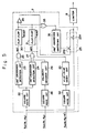
- Figs. 1, 3 and 5 show a system for controlling the rotation of a rotary housing mounting a propeller unit of a Z-type propulsion apparatus according to the present invention.
- reference numeral 1 denotes a steering handle for commanding a rotary housing 2 mounting a propeller unit of a Z-type propulsion apparatus to rotate, the rotary housing 2 being rotatably mounted on a hull.
- the steering handle 1 is connected to an angular position detector 3 comprising a well-known potentiometer or the like which outputs a sinusoidal voltage sin 81 and a cosine voltage cos 81 in accordance with the angular position 81 (steering angle) of the steering handle 1.
- Another angular position detector 4 such as a potentiometer is connected to a worm shaft 5 through a gear mechanism, the potentiometer outputting a sinusoidal voltage sin 02 and a cosine voltage cos 82 (follow-up angle) in accordance with the angular position 82 of the rotary housing 2.
- the output voltages sin 81 and cos 81 of the angular position detector 3 and the output voltages sin 82 and cos ⁇ 2 of the angular position detector 4 are inputted to the calculation circuit 6 (vector calculation circuit).
- the calculation circuit 6 produces a first sinusoidal signal sin ( ⁇ 1- ⁇ 2) and a cosine signal cos ( ⁇ 1- ⁇ 2) of an angle (81-82) representative of the difference of angle between the steering angle 81 and the follow-up angle 82, and also produces a second sinusoidal signal sin ( ⁇ 1- ⁇ 2+45°) of an angle ( ⁇ 1- ⁇ 2+45°) which is obtained by adding 45° to the difference of angle ( ⁇ 1- ⁇ 2).
- These signals sin (81-82), cos ( ⁇ 1- ⁇ 2) and sin ( ⁇ 1- ⁇ 2+45°) are inputted to a signal processing circuit 7.
- the calculation circuit 6 comprises multipliers MUL1 to MUL4, a subtractor SUB1 and adders ADD1 and ADD2. These operational devices may be constituted of analog circuits including operational amplifiers or of digital circuits including a microprocessor.
- the signal processing circuit 7 is connected to a limiter 8, and this limiter 8 is connected to a servo control circuit 9 for controlling a servomotor 10.
- the servomotor 10 is connected to a hydraulic pump 11 which is coupled to a hydraulic cylinder 14 through connecting tubes 12 and 13.
- the piston 14a of the hydraulic cylinder 14 is linked to a control lever 15a of a hydraulic pump 15 to control the direction and amount of the oil passing therethrough, the hydraulic pump 15 being connected to an electric motor 16.
- the hydraulic pump 15 is coupled through connecting tubes 17 and 18 to a hydraulic motor 19 which is linked to a worm wheel 21 through a warm 20 formed on a shaft 5, and the worm wheel 21 is connected to the rotary housing 2.
- the sinusoidal signal sin (81-82) inputted to the signal processing circuit 7 is supplied through a square wave circuit 22 to a +180° crossover detection circuit 23 and to a -180° crossover detection circuit 24, the square wave circuit 22 shaping the waveform of the signals inputted thereto into square waves.
- the +180° crossover detection circuit 23 detects the positive to negative change of the polarity of the sinusoidal signal sin ( ⁇ 1- ⁇ 2) when the difference of angle ( ⁇ 1- ⁇ 2) becomes 180° while the -180° crossover detection circuit 24 detects the negative to positive change of the polarity of the sinusoidal signal sin ( ⁇ 1- ⁇ 2) when the difference of angle ( ⁇ 1- ⁇ 2) becomes -180°.
- the sinusoidal signal sin ( ⁇ 1- ⁇ 2) is also supplied through contacts 25a of a signal switching circuit 25 to the limiter 8 which limits the amplitude of the inputted signal to a predetermined range.
- An output terminal of the +180° crossover detection circuit 23 is connected to one input terminal of an AND circuit 26, while an output terminal of the -180° crossover detection circuit 24 is connected to one input terminal of another AND circuit 27.
- the cosine signal cos (81-82) inputted to the signal processing circuit 7 is supplied through a square wave circuit 28 to a polarity decision circuit 29 which outputs a H level signal when the cosine signal cos (81-82) is negative.
- An output terminal of the polarity decision circuit 29 is connected to the other input terminal and the AND circuit 26 and to the other input terminal of the AND circuit 27.
- An output terminal of the AND circuit 26 is connected to a SET terminal of a flip-flop 30, while an output terminal of the AND circuit 27 is connected to a SET terminal of another flip-flop 31.
- the sinusoidal signal sin ( ⁇ 1- ⁇ 2+45°) inputted to the signal processing circuit 7 is supplied through a square wave circuit 32 to a flip-flop reset circuit 33.
- This flip-flop reset circuit 33 is connected to a RESET terminal of the flip-flop 30 and to a RESET terminal of the flip-flop 31.
- an output terminal of the flip-flop 30 is connected to a +input terminal of an operational amplifier 34 and to one input terminal of an OR circuit 35.
- An output terminal of the flip-flop 31 is connected to a -input terminal of the operational amplifier 34 and to the other input terminal of the OR circuit 35.
- An output terminal of the operational amplifier 34 is connected through contacts 25b of the signal switching circuit 25 to the input terminal of the limiter 8, and an output terminal of the OR circuit 35 is connected to the ⁇ 180° crossover switching circuit 36.
- This ⁇ 180° crossover switching circuit 36 closes the contacts 25b of the signal switching circuit 25 when a H level signal is inputted thereto, and closes the contacts 25a when a L level signal is inputted thereto.
- the steering handle 1 begins to be pivotally moved when the steering angle 61 of the steering handle 1 and the follow-up angle 82 of the rotary housing 2 are equal to each other. In this case, a difference of angle appears between the steering angle 61 and the follow-up angle 62. It is also assumed that the difference of angle ( ⁇ 1- ⁇ 2) becomes positive when the steering handle 1 is pivoted clockwise and that the difference of angle ( ⁇ 1- ⁇ 2) becomes negative when the steering handle 1 is pivoted counterclockwise.
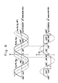
- the output signals sin 61 and cos 81 of the angular position detector 3 and the output signals sin ⁇ 2 and cos 82 of the angular position detector 4 are inputted to the calculation circuit 6 which in turn executes a calculation using these signals to form three kinds of signals, i.e., the sinusoidal signals sin ( ⁇ 1- ⁇ 2) and sin ( ⁇ 1- ⁇ 2+45°) and the cosine signal cos (81-82) (see Fig. 6).
- the waveforms of the signals sin ( ⁇ 1- ⁇ 2), sin ( ⁇ 1- ⁇ 2+45°) and cos ( ⁇ 1- ⁇ 2) outputted from the calculation circuit 6 are shaped into square waves by the square wave circuits 22, 23 and 28, respectively.
- the difference of angle ( ⁇ 1- ⁇ 2) is within the range of between -180° and +180°, i.e., both of the +180° crossover detection circuit 23 and -180° crossover detection circuit 24 do not operate, so that the ⁇ 180° crossover switching circuit 36 opens the contacts 25b of the signal switching circuit 36 and closes the contacts 25a of the same.
- the sinusoidal signal sin ( ⁇ 1- ⁇ 2) is inputted to the limiter 8 intactly.
- the output signal SI of the limiter 8 is therefore a signal derived from the sinusoidal signal sin (81-82) with its amplitude limited to the values determined by the limiter 8.
- the flip-flop reset circuit 33 resets the flip-flop 31 (see the waveform indicated by the dot and dash line in Fig. 6), so that the ⁇ 180° crossover switching circuit 36 opens the contacts 25b of the signal switching circuit 25 and closes contacts 25a of the same.
- the sinusoidal signal sin (81-82) is intactly supplied to the input terminal of the limiter 8.
- the signal thus inputted to the limiter 8 is outputted to the servo control circuit 9 as the signal Sl whose amplitude has been limited to predetermined levels by the limiter 8, as shown in Fig. 6.
- the servo control circuit 9 controls the servomotor 9 in accordance with the signal Sl, and the servomotor 9 controls the hydraulic motor 19 through the hydraulic pump 11, the hydraulic cylinder 14 and the hydraulic pump 15 to rotate the worm 20 of the shaft 5 in accordance with its rotational movement.
- the worm wheel 21 rotates so that the rotary housing 2 of the Z-type propulsion apparatus begins to rotate in unison with the steering handle 1 in the direction of rotation thereof. And when the difference of angle ( ⁇ 1- ⁇ 2) reaches 0 the rotary housing 2 stops.
- the signal processing circuit 7 can control the rotary housing 2 so as to rotate in unison with the steering handle 1 in the direction of rotation thereof on condition that the difference of angle (81-82) is within the range of between -225° and +315°, i.e.,
- the sinusoidal signals sin (81-82) and sin ( ⁇ 1- ⁇ 2+45°) and the cosine signal cos (81-82) may alternatively be obtained by employing synchros and Scott transformers and removing the ac components from its output signals. These sinusoidal and cosine signals may also be obtained by employing resolvers and differential transformers or by employing rotary encoders or the like.
- FIG. 7 shows a second embodiment of the present invention in which like references denote same parts of the first embodiment of the invention.
- a calculation circuit 6a of this system is so constructed as to supply the sinusoidal signal sin (81-82) representing a sine of the difference of angle (81-82) between the angular position 81 of the steering handle 1 and the angular position 82 of the rotary housing 2 to a sample and hold circuit 38 of a signal processing circuit 7a and to supply the cosine signal cos ( ⁇ 1- ⁇ 2) representing a cosine of the difference of angle (81-82) to a polarity decision circuit (comparator) 39 of the signal processing circuit 7a.
- the polarity decision circuit 39 detects the polarity of the cosine signal cos (81-82) and feeds the detection result to the sample and hold circuit 38.
- the sample and hold circuit 38 is so constructed as to hold the inputted signal when the polarity decision circuit 39 detects a negative signal, and an output terminal of this sample and hold circuit 38 is connected to the limiter 8.
- the limiter 8 is connected to the servo control circuit 9 for controlling the servomotor 10.
- the calculation circuit 6a executes a calculation using the output signals sin 81 and cos 81 of the angular position detector 3 and the output signals sin 82 and cos 82 of the angular position detector 4 to form two kinds of signals, i.e., the sinusoidal signal sin (81-82) and the cosine signal cos (81-82), (see Fig. 8).
- the polarity decision circuit 39 detects the polarity of the cosine signal cos (81-82) outputted from the calculation circuit 6a and brings the sample and hold circuit 38 into a sample mode A when the cosine signal cos (81 -82) is equal to or more than a predetermined value 0 (cos ( ⁇ 1- ⁇ 2) ⁇ 0).
- the sinusoidal signal sin (81-82) outputted from the calculation circuit 6a to the sample and hold circuit 38 is intactly supplied to the limiter 8.
- the polarity decision circuit 39 brings the sample and hold circuit 38 into a hold mode B when the cosine signal cos (81-82) is less than 0 (cos ( ⁇ 1- ⁇ 2) ⁇ 0).
- a signal representative of the value sin (+90°) is inputted to the limiter 8 when the difference of angle ( ⁇ 1- ⁇ 2) is greater than 90° ((81-A2)>90°)
- a signal representative of the value sin (-90°) is inputted to the limiter 8 when the difference of angle ( ⁇ 1- ⁇ 2) is less than 90° ((81-82) ⁇ 90°).
- An output signal Ss of the sample and hold circuit 38 is the sinusoidal signal sin (81-82) itself outputted from the calculation circuit 6a when the difference of angle (81 -82) is between
- the signal Ss is a signal representative of the value sin (-90°) when the difference of angle (61-82) is between and is a signal representative of the value sin (+90°) when the difference of angle ( ⁇ 1- ⁇ 2) is between
- the limiter 8 limits the amplitude of the output signal of the sample and hold circuit 38 to form a signal SI shown in Fig. 8 and feeds it to the servo control circuit 9.
- the servo control circuit 9 controls the servomotor 10 in accordance with the signal SI, and the servomotor 10 controls the hydraulic motor 19 through the hydraulic pump 11, the hydraulic cylinder 14 and the hydraulic pump 15 to rotate the worm 20 of the shaft 5.
- the worm wheel 21 rotates so that the rotary housing 2 of the Z-type propulsion apparatus begins to rotate in unison with the steering handle 1 in the direction of the rotation thereof. And when the difference of angle ( ⁇ 1- ⁇ 2) reaches 0 the rotary housing 2 stops.
- the signal processing circuit 7a can control the rotary housing 2 to rotate in unison with the steering handle 1 in the direction of rotation thereof on condition that the difference of angle ( ⁇ 1- ⁇ 2) is within the range of between -270° and +270°, i.e.,
- the polarity decision circuit 39 is so constructed as to hold and output the sinusoidal signal sin ( ⁇ 1- ⁇ 2) when the cosine signal cos ( ⁇ 1- ⁇ 2) is negative, however the circuit 39 may be modified so as to hold the sinusoidal signal sin ( ⁇ 1- ⁇ 2) when the cosine signal cos (81-82) is less than a predetermined value other than 0.
- the sample and hold circuit 38 does not hold the sinusoidal signal sin ( ⁇ 1- ⁇ 2) when the difference of angle ( ⁇ 1- ⁇ 2) is between or when the difference of angle ( ⁇ 1- ⁇ 2) is between Therefore, if the steering handle is operated to command such a rapid rotation of the rotary housing 2, which is beyond the response characteristic of the mechanical system, that the absolute value of the difference of angle (81-82) becomes greater than ⁇ 270°, the rotary housing 2 rotates in the direction opposite to that of rotation of the steering handle 1.
- the steering handle is usually operated in such a manner that the rotary housing rotates not in the forward direction beyond 180° but in the reverse direction. Actually, it is rare to command the rotary housing to rotate by more than ⁇ 270°, so that any significant problem will not be encountered.
- Fig. 9 shows a third embodiment of the invention in which like references denote same parts of the second invention.
- the sinusoidal signal sin ( ⁇ 1- ⁇ 2) outputted from the calculation circuit 6a is supplied to the sample and hold circuit 38 of a signal processing circuit 7b and to one input terminal of a polarity comparator 40.
- the cosine signal cos ( ⁇ 1- ⁇ 2) outputted from the circuit 6a is fed to the polarity decision circuit 39 of the signal processing circuit 7b.
- An output signal of the sample and hold circuit 38 is supplied to the input terminal of the servo control circuit 9 and to the other input terminal of the polarity comparator 40.
- the polarity decision circuit 39 outputs a true signal when the cosine signal cos (81-82) is negative, and the polarity comparator 40 outputs a true signal when the two input signals are different in polarity to each other.
- the output signals of the polarity decision circuit 39 and the polarity comparator 40 are logically added by an OR circuit 41, and the resultant signal is fed to the sample and hold circuit 38.
- the sample and hold circuit 38 holds its input signal. And when the signal S1 is false, the circuit 38 samples its input and outputs it.
- the cosine signal cos (81 -82) becomes less than 0, so that a true signal is outputted from the polarity decision circuit 39.
- the OR circuit 41 outputs the signal S1 (hold signal) to bring the sample and hold circuit 38 into the hold mode B, so that the circuit 38 outputs a signal representative of the value sin (+90°), i.e., the sinusoidal signal sin (81-82) at the moment when the difference of angle (81-82) is equal to +90°.
- the hold mode B is maintained so long as the difference of angle (81-82) is between If the difference of angle exceeds +270°, the cosine signal cos (81-62) becomes positive.
- the polarities of the input and output signals of the sample and hold circuit 38 differs from each other, so that the polarity comparator 40 outputs a true signal, thereby the hold signal S1 being outputted from the OR circuit 41.
- the sample and hold circuit 38 is brought into the hold mode C to output the positive value sin (+90°).
- the hold mode C is maintained so long as the difference of angle (61-82) is between since the polarity of the output of the sample and hold circuit 38 differs from that of the sinusoidal signal sin ( ⁇ 1- ⁇ 2).
- the OR circuit 41 outputs the hold signal S1, so that the sample and hold circuit 38 is brought into the hold mode B to output sin (-90 0 ), i.e., the value of the sinusoidal signal sin (81-82) at the moment when the difference of angle ( ⁇ 1- ⁇ 2) is equal to -90°.
- the hold mode B is maintained so long as the difference of angle (81-82) is between If the difference of angle (81-82) becomes less than -270°, the cosine signal cos ( ⁇ 1- ⁇ 2) becomes positive.
- the polarity comparator 40 outputs a true signal, since the polarities of the input and output of.the sample and hold circuit 38 are different from each other.
- the OR circuit 41 outputs the signal S1, so that the sample and hold circuit 38 is brought into the hold mode C to output the negative value sin (-90 0 ).
- the hold mode is maintained so long as the difference of angle (81-82) is between since the polarities of the input and output of the sample and hold circuit 38 differ from each other.
- the rotary housing 2 is controlled to rotate in unison with the steering handle 1 in the direction of rotation thereof on condition that the difference of angle (81 -82) is within the range of ⁇ 360°.
- the polarity decision circuit 39 may be modified so as to output a true signal when the cosine signal cos (81-82) is less than a predetermined value other than 0.
- Fig. 10 shows a fourth embodiment of the present invention.
- a signal processing circuit 7c of this system the both signals at the input and output terminals of the sample and hold circuit 38 are inputted to both input terminals of an error detection circuit 42.
- the error detection circuit 42 detects the difference (error) between the two signals inputted thereto and outputs the error to an error comparator 43.
- the error comparator 43 is constructed in such a manner that it outputs a true signal when the output of the error detection circuit 42 is greater than a predetermined value (for example, 1 corresponding to the value sin 90°).
- the output of the error comparator 43 is supplied to the other input terminal of the OR circuit 41.
- the OR circuit 41 outputs the signal S1 to bring the sample and hold circuit 38 into the hold mode B, so that the circuit 38 outputs a signal representing the value sin (+90°), i.e., the sinusoidal signal sin (81 -82) at the moment when the difference of angle (81 -82) is equal to +90°.
- the hold mode B is maintained so long as the difference of angle (81 -82) is between If the difference of angle ( ⁇ 1- ⁇ 2) exceeds +270°, the cosine signal cos ( ⁇ 1- ⁇ 2) becomes positive.
- the output (error) of the error detection circuit 42 is greater than the value predetermined at the error comparator 43 (it is assumed herein that the predetermined value is 1), so that the error comparator 43 outputs a true signal, thereby the hold signal S1 being outputted from the OR circuit 41.
- the sample and hold circuit 38 is brought into the hold mode C to output the positive value sin (+90°).
- the OR circuit 41 outputs the hold signal S1, so that the sample and hold circuit 38 is brought into the hold mode B to output sin (-90 0 ), i.e., the value of the sinusoidal signal sin (81-82) at the moment when the difference of angle ( ⁇ 1- ⁇ 2) is equal to -90°.
- the hold mode B is maintained so long as the difference of angle (81-82) is between If the difference of angle (81-82) becomes less than -270°, the cosine signal cos (81-82) becomes positive.
- the OR circuit 41 outputs the signal S1, so that the sample and hold circuit 38 is brought into the hold mode C to output the negative value sin (-90 0 ):
- the hold mode C is maintained so long as the difference of angle (81-82) is between since the difference between the output and input of the sample and hold circuit 38 is greaterthan the predetermined value.
- the rotary housing 2 is controlled to rotate in unison with the steering handle 1 in the direction of rotation thereof on condition that the difference of angle ( ⁇ 1- ⁇ 2) is within the range of ⁇ 360°.
- a limiter circuit may be provided at the input terminal of the servo control circuit 9 to limit the amplitude of the output signal of the sample and hold circuit 38 to appropriate values.
- the value predetermined at the error comparator 43 is 1, however, the value may be increased or decreased from 1 to expand or reduce the hold mode range.
- the polarity duration circuit 39 may be modified so as to output a true signal when its input becomes less than a predetermined value other than 0.
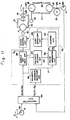
- Fig. 11 shows a fifth embodiment of the present invention.
- a signal processing circuit 7d of this system shown in this figure differs from those of the second to fourth embodiments in the following respects.
- the sinusoidal signal sin ( ⁇ 1- ⁇ 2) outputted from the calculation circuit 6a is supplied to the input terminal of the sample and hold circuit 38 and to an input terminal of a polarity decision circuit 44.
- the polarity decision circuit 44 outputs a signal S2 indicating whether the sinusoidal signal sin ( ⁇ 1- ⁇ 2) is positive or negative.
- the cosine signal cos ( ⁇ 1- ⁇ 2) outputted from the calculation circuit 6a is supplied to a polarity-inversion detection circuit 45.
- the polarity-inversion detection circuit 45 outputs a pulse signal P when a positive to negative or a negative to positive change of the polarity of the cosine signal cos ( ⁇ 1- ⁇ 2) is detected.
- the pulse signal P is fed to a pulse generating circuit 46.
- the circuit 46 When the pulse signal P is inputted to the the pulse generating circuit 46 with a signal S2 representing a polarity of the sinusoidal signal sin ( ⁇ 1- ⁇ 2) different from that represented by it when the preceding pulse signal P is generated, the circuit 46 outputs one of an increment pulse P1 and a decrement pulse P2 which is the same as the pulse precedingly outputted therefrom.
- the pulse generating circuit 46 outputs one of the increment and decrement pulses which is of the type different from that of the pulse precedingly outputted therefrom, when the pulse signal P is inputted thereto with the signal S2 representing the same polarity of the signal sin ( ⁇ 1- ⁇ 2) as that represented by it when the preceding pulse signal P is generated.
- the increment and decrement pulses are fed to a counter circuit 47.
- the count value outputted from the counter circuit 47 is supplied to a zero detection circuit 48 to decide whether the value is zero or not.
- This zero detection circuit 48 brings the sample and hold circuit 38 into a sample mode when the count value of the counter circuit 47 is zero, while it brings the sample and hold circuit into a hold mode when the count value is other than 0.
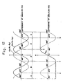
- the cosine signal ( ⁇ 1- ⁇ 2) changes its polarity from a positive to a negative state, as indicated by an arrow a in Fig. 12, so that pulse signal P is outputted from the polarity-inversion detection circuit 45.
- the polarity decision circuit 44 outputs to the pulse generating circuit 46 signal S2 indicating that the sinusoidal signal sin ( ⁇ 1- ⁇ 2) is positive.
- the pulse generating circuit 46 stores the state indicating that the sinusoidal signal sin ( ⁇ 1- ⁇ 2) is positive and atthe same time outputs increment pulse P1 to the counter circuit 47 since the contents of the counter circuit 47 is 0.
- the count value of the counter circuit 47 is incremented from 0 to +1, which causes the zero detection circuit 48 to output the hold signal to the sample and hold circuit 38.
- the sample and hold circuit 38 therefore holds and outputs (hold mode) sin (-90°), i.e., the value of the sinusoidal signal sin (81-82) at the moment when the difference of angle ( ⁇ 1- ⁇ 2) is equal to -90°.
- the pulse generating circuit 46 compares the polarity of the sinusoidal signal sin ( ⁇ 1- ⁇ 2) at that moment with the polarity of the sinusoidal signal sin (81-82) stored by itself at the moment of the preceding change of the polarity of the cosine signal cos (61-82). And if the both polarities differ from each other, the pulse generating circuit 46 outputs to the counter circuit 47 the same kind of pulse signal (pulse signal in the same count direction) as that precedingly outputted therefrom, the pulse signal being an incremental pulse signal or a decremental pulse signal.
- the pulse generating circuit 46 outputs a pulse signal in the different count direction to the counter circuit 47.
- the contents of the counter circuit 47 is incremented or decremented by the pulse signal.
- the polarity of the cosine singal cos (81-82) changes from positive to negative as indicated by an arrow c in Fig. 12, so that the polarity-inversion circuit 45 outputs the pulse signal P.
- the polarity decision circuit 44 outputs a signal indicating that the sinusoidal signal sin ( ⁇ 1- ⁇ 2) is negative.
- the pulse generating circuit 46 stores the negative polarity of the sinusoidal signal sin ( ⁇ 1- ⁇ 2), and outputs the increment pulse P1 to the counter circuit 47 since the contents of the counter circuit 47 is zero.
- the contents of the counter circuit 47 is incremented from 0 to +1, so that the zero detection circuit 48 outputs the holding signal to the sample and hold circuit 38.
- the sample and hold circuit 38 holds and outputs (hold mode) sin (-90°), i.e., the value of the sinusoidal signal sin ( ⁇ 1- ⁇ 2) at the moment when the difference of angle ( ⁇ 1- ⁇ 2) is equal to -90°.
- the counter circuit 47 is supplied with an increment pulse to increment the contents thereof from 0 to 1 when the difference of angle ( ⁇ 1- ⁇ 2) becomes less than -90°
- this system may be modified so that when the difference of angle ( ⁇ 1- ⁇ 2) becomes less than -90° decrement pulse P2 is supplied to the counter circuit 47 to decrement its contents from 0 to -1.
- the follow-up angle 82 remains 0 since the follow-up operation has not yet been commenced, so that only the steering angle 81 begins to increase. And when the steering angle 81 exceeds +90° the difference of angle ( ⁇ 1- ⁇ 2) exceeds +90°, so that the polarity of the cosine signal cos ( ⁇ 1- ⁇ 2) is changed from a positive to a negative state. At this moment, the polarity of the sinusoidal signal sin ( ⁇ 1- ⁇ 2) is positive, and the contents of the counter circuit 47 is 0.
- the pulse generator 46 therefore memorizes the positive polarity of the sinusoidal signal sin ( ⁇ 1- ⁇ 2) and outputs increment pulse P1 to increment the contents of the counter circuit 47 from 0 to + 1.
- the sample and hold circuit 38 which has outputted the sinusoidal signal sin (81-82) intactly (sample mode) until then, holds and outputs (hold mode) the value sin (+90°).
- the difference of angle ( ⁇ 1- ⁇ 2) also exceeds +270°, so that the polarity of the cosine signal cos ( ⁇ 1- ⁇ 2) is changed from a negative to a positive state.
- the polarity of the sinusoidal signal sin ( ⁇ 1- ⁇ 2) is negative, and the pulse generating circuit 46 compares this polarity with the polarity of the signal sin ( ⁇ 1- ⁇ 2) precedingly stored thereinto.
- the polarity precedingly stored is positive and the present polarity is negative, so that the pulse generating circuit 46 stores the present polarity thereinto and outputs the same kind of pulse signal (increment pulse P1) as that previously outputted therefrom.
- the count value of the counter circuit 47 is incremented from +1 to +2.
- the resultant count value of the counter circuit 47 is not 0, so that the sample and hold circuit 38 continues to output the value sin (+90°).
- the steering angle 01 becomes +300° the follow-up operation is commenced, so that the follow-up angle A2 begins to increase, thereby the difference of angle ( ⁇ 1- ⁇ 2) being decreased.
- the polarity of the cosine signal cos ( ⁇ 1- ⁇ 2) is changed from a positive to a negative state.
- the polarity of the sinusoidal signal sin ( ⁇ 1- ⁇ 2) is negative, so that the pulse generating circuit 46 stores the present polarity of the signal sin ( ⁇ 1- ⁇ 2) and outputs a pulse signal (decrement pulse P2) which is of the kind different from that of the pulse signal precedingly outputted therefrom.
- the count value of the counter circuit 47 is decremented from +2 to +1.
- the sample and hold circuit 38 therefore continues to output the value sin (+90°).
- the pulse generating circuit 46 When the difference of angle (61-82) is decreased to less than +90°, the polarity of the cosine signal cos ( ⁇ 1 ⁇ 2) is changed from a negative to a positive state.
- the polarity of the sinusoidal signal sin (81 -82) at this time is positive and the polarity of the signal sin (81-82) precedingly stored is negative, the pulse generating circuit 46 therefore outputs the same kind of pulse signal (decrement pulse P2) as that precedingly outputted therefrom.
- the count value of the counter circuit 47 is decreased from +1 to 0, so that the sample and hold circuit 38 is released from its hold mode and outputs the sinusoidal signal sin (81-82) intactly (sample mode).
- the follow-up operation is completed.
- the rotary housing 2 is controlled to rotate in unison with the steering handle in the direction of rotation thereof. And if the counting capacity of the counter circuit 47 is increased the rotary housing 2 can be controlled to rotate a plurality of revolutions in unison with the steering handle.
- the system may also be modified by setting the counting capacity to an appropriate value so as to restrict the maximum number of its revolutions to a specific value.
- the ratio of the steering angle 81 to the follow-up angle 82 is not limited to 1:1 but can be changed to 1:n or n:1 to enhance the accuracy of the operation.
- the construction for effecting the counting operation at the counter circuit 47 may be modified so that the polarity of the cosine signal cos (81-82) immediately after a change of the polarity of the same is compared with that of the sinusoidal signal sin (81-82) to decide which pulse should be generated an increment pulse or a decrement pulse.
- the pulse generating circuit 46 is modified so that it outputs a decrement pulse to the counter circuit 47 to decrement its contents by one when the two polarities coincide with each other and that the circuit 46 outputs an increment pulse to the counter circuit 47 to increment its contents by one when the two polarities are different from each other.
- the rotation control system according to the present invention is particularly suitable for controlling the rotation of a rotary housing mounting a propeller unit of a Z-type propulsion apparatus mounted on a vessel such as a tug boat which is required to be steered in a rapid manner and to make a small turn.
Landscapes
- Engineering & Computer Science (AREA)
- Radar, Positioning & Navigation (AREA)
- Combustion & Propulsion (AREA)
- Mechanical Engineering (AREA)
- Ocean & Marine Engineering (AREA)
- Aviation & Aerospace Engineering (AREA)
- Chemical & Material Sciences (AREA)
- Remote Sensing (AREA)
- Physics & Mathematics (AREA)
- General Physics & Mathematics (AREA)
- Automation & Control Theory (AREA)
- Measurement Of Length, Angles, Or The Like Using Electric Or Magnetic Means (AREA)
- Control Of Position Or Direction (AREA)
Claims (7)
Applications Claiming Priority (10)
| Application Number | Priority Date | Filing Date | Title |
|---|---|---|---|
| JP46139/83U | 1983-03-30 | ||
| JP4613983U JPS59150698U (ja) | 1983-03-30 | 1983-03-30 | Z型推進装置における逆旋回防止装置 |
| JP4613883U JPS59150697U (ja) | 1983-03-30 | 1983-03-30 | Z型推進装置における逆旋回防止装置 |
| JP46138/83U | 1983-03-30 | ||
| JP82607/83U | 1983-05-31 | ||
| JP8260683U JPS59187599U (ja) | 1983-05-31 | 1983-05-31 | Z型推進装置 |
| JP82606/83U | 1983-05-31 | ||
| JP8260583U JPS59187598U (ja) | 1983-05-31 | 1983-05-31 | Z型推進装置 |
| JP82605/83U | 1983-05-31 | ||
| JP8260783U JPS59187600U (ja) | 1983-05-31 | 1983-05-31 | Z型推進装置 |
Publications (3)
| Publication Number | Publication Date |
|---|---|
| EP0139766A1 EP0139766A1 (de) | 1985-05-08 |
| EP0139766A4 EP0139766A4 (de) | 1987-10-27 |
| EP0139766B1 true EP0139766B1 (de) | 1989-03-15 |
Family
ID=27522527
Family Applications (1)
| Application Number | Title | Priority Date | Filing Date |
|---|---|---|---|
| EP84901407A Expired EP0139766B1 (de) | 1983-03-30 | 1984-03-30 | Lenkungssteuervorrichtung für antriebsvorrichtungen vom z-typ |
Country Status (4)
| Country | Link |
|---|---|
| US (1) | US4610214A (de) |
| EP (1) | EP0139766B1 (de) |
| DE (1) | DE3477179D1 (de) |
| WO (1) | WO1984003870A1 (de) |
Families Citing this family (2)
| Publication number | Priority date | Publication date | Assignee | Title |
|---|---|---|---|---|
| SE465160B (sv) * | 1989-12-14 | 1991-08-05 | Volvo Penta Ab | Elektromagnetisk styranordning foer baatar |
| DE19813635A1 (de) * | 1998-03-27 | 1999-09-30 | Jost Werke Ag | Sattelkupplung |
Family Cites Families (6)
| Publication number | Priority date | Publication date | Assignee | Title |
|---|---|---|---|---|
| US2565781A (en) * | 1945-05-19 | 1951-08-28 | Bofors Ab | Device for the remote transmission of rotary movements with correct angular displacement |
| NL179421C (nl) * | 1976-02-12 | 1986-09-01 | Stork Kwant Bv | Besturingsstelsel met een aantal bedieningsorganen. |
| US4074648A (en) * | 1976-10-18 | 1978-02-21 | Sperry Rand Corporation | Adaptive autopilot for marine vessels |
| JPS5472895A (en) * | 1977-11-18 | 1979-06-11 | Nippon Zousen Kikai Kk | Steering apparatus for z shaft propelling device |
| US4346334A (en) * | 1980-07-23 | 1982-08-24 | Brother Kogyo Kabushiki Kaisha | DC Servomotor system |
| US4429267A (en) * | 1981-06-22 | 1984-01-31 | Manhattan Engineering Company, Inc. | Digital positioning systems having high accuracy |
-
1984
- 1984-03-30 EP EP84901407A patent/EP0139766B1/de not_active Expired
- 1984-03-30 US US06/682,012 patent/US4610214A/en not_active Expired - Lifetime
- 1984-03-30 DE DE8484901407T patent/DE3477179D1/de not_active Expired
- 1984-03-30 WO PCT/JP1984/000157 patent/WO1984003870A1/ja not_active Ceased
Also Published As
| Publication number | Publication date |
|---|---|
| EP0139766A4 (de) | 1987-10-27 |
| WO1984003870A1 (fr) | 1984-10-11 |
| US4610214A (en) | 1986-09-09 |
| DE3477179D1 (en) | 1989-04-20 |
| EP0139766A1 (de) | 1985-05-08 |
Similar Documents
| Publication | Publication Date | Title |
|---|---|---|
| US4055135A (en) | Rudder error detector | |
| EP0143851A1 (de) | Lenkungssteuerung für antriebsvorrichtungen vom z-typ | |
| CN108482631B (zh) | 一种多台全回转舵桨的控制系统及控制方法 | |
| CN105836085A (zh) | 一种可调螺距螺旋桨的控制方法和装置 | |
| EP0139766B1 (de) | Lenkungssteuervorrichtung für antriebsvorrichtungen vom z-typ | |
| US4117386A (en) | Digital continuous potentiometer servo feedback element | |
| CA1215445A (en) | System for controlling rotation of propeller unit of z-type propulsion apparatus | |
| EP0770947B1 (de) | Positionierungsvorrichtung | |
| JPH08216989A (ja) | 船舶の自動操船装置 | |
| US3943764A (en) | Sailboat steering indicator system | |
| US3460278A (en) | Control for a dragline | |
| JPH0137999Y2 (de) | ||
| US4022150A (en) | Sailboat steering indicator system | |
| US3481299A (en) | Control apparatus | |
| JP2510389B2 (ja) | 船体運動指示方法および舵角指示方法 | |
| US3987744A (en) | Automatic systems for the dynamically positioning of a floating vessel | |
| US3665281A (en) | Autopilot for ship | |
| JPH0113040Y2 (de) | ||
| US3699420A (en) | Automatic control system controlling the course of a ship | |
| NO167242B (no) | Rotasjonsstyresystem for fremdriftsutstyr av z-typen. | |
| JPH0113037Y2 (de) | ||
| JPH0113039Y2 (de) | ||
| JPH0113038Y2 (de) | ||
| US3020459A (en) | Analog-voltage shaft positioning system | |
| SU1004977A1 (ru) | Устройство дл управлени электроприводом |
Legal Events
| Date | Code | Title | Description |
|---|---|---|---|
| PUAI | Public reference made under article 153(3) epc to a published international application that has entered the european phase |
Free format text: ORIGINAL CODE: 0009012 |
|
| 17P | Request for examination filed |
Effective date: 19841205 |
|
| AK | Designated contracting states |
Designated state(s): DE GB NL |
|
| A4 | Supplementary search report drawn up and despatched |
Effective date: 19871027 |
|
| 17Q | First examination report despatched |
Effective date: 19880328 |
|
| GRAA | (expected) grant |
Free format text: ORIGINAL CODE: 0009210 |
|
| AK | Designated contracting states |
Kind code of ref document: B1 Designated state(s): DE GB NL |
|
| REF | Corresponds to: |
Ref document number: 3477179 Country of ref document: DE Date of ref document: 19890420 |
|
| PLBE | No opposition filed within time limit |
Free format text: ORIGINAL CODE: 0009261 |
|
| STAA | Information on the status of an ep patent application or granted ep patent |
Free format text: STATUS: NO OPPOSITION FILED WITHIN TIME LIMIT |
|
| 26N | No opposition filed | ||
| REG | Reference to a national code |
Ref country code: GB Ref legal event code: IF02 |
|
| PGFP | Annual fee paid to national office [announced via postgrant information from national office to epo] |
Ref country code: GB Payment date: 20020222 Year of fee payment: 19 |
|
| PGFP | Annual fee paid to national office [announced via postgrant information from national office to epo] |
Ref country code: NL Payment date: 20020328 Year of fee payment: 19 |
|
| PGFP | Annual fee paid to national office [announced via postgrant information from national office to epo] |
Ref country code: DE Payment date: 20020531 Year of fee payment: 19 |
|
| PG25 | Lapsed in a contracting state [announced via postgrant information from national office to epo] |
Ref country code: GB Free format text: LAPSE BECAUSE OF NON-PAYMENT OF DUE FEES Effective date: 20030330 |
|
| PG25 | Lapsed in a contracting state [announced via postgrant information from national office to epo] |
Ref country code: NL Free format text: LAPSE BECAUSE OF NON-PAYMENT OF DUE FEES Effective date: 20031001 Ref country code: DE Free format text: LAPSE BECAUSE OF NON-PAYMENT OF DUE FEES Effective date: 20031001 |
|
| GBPC | Gb: european patent ceased through non-payment of renewal fee |
Effective date: 20030330 |
|
| NLV4 | Nl: lapsed or anulled due to non-payment of the annual fee |
Effective date: 20031001 |