EP0139600A2 - Hintergrundprojektionsvorrichtung für photographische Aufnahmen - Google Patents
Hintergrundprojektionsvorrichtung für photographische Aufnahmen Download PDFInfo
- Publication number
- EP0139600A2 EP0139600A2 EP84420159A EP84420159A EP0139600A2 EP 0139600 A2 EP0139600 A2 EP 0139600A2 EP 84420159 A EP84420159 A EP 84420159A EP 84420159 A EP84420159 A EP 84420159A EP 0139600 A2 EP0139600 A2 EP 0139600A2
- Authority
- EP
- European Patent Office
- Prior art keywords
- lens
- image
- torch
- camera
- objective
- Prior art date
- Legal status (The legal status is an assumption and is not a legal conclusion. Google has not performed a legal analysis and makes no representation as to the accuracy of the status listed.)
- Withdrawn
Links
- 238000005034 decoration Methods 0.000 claims abstract description 12
- 230000001360 synchronised effect Effects 0.000 claims abstract description 4
- 239000011521 glass Substances 0.000 claims description 2
- 238000004519 manufacturing process Methods 0.000 abstract description 5
- 230000000694 effects Effects 0.000 description 5
- 239000003086 colorant Substances 0.000 description 1
- 238000001816 cooling Methods 0.000 description 1
- 230000006378 damage Effects 0.000 description 1
- 239000004744 fabric Substances 0.000 description 1
- 238000009434 installation Methods 0.000 description 1
- 230000007935 neutral effect Effects 0.000 description 1
- 239000003973 paint Substances 0.000 description 1
- 238000005096 rolling process Methods 0.000 description 1
- 230000001960 triggered effect Effects 0.000 description 1
Images
Classifications
-
- G—PHYSICS
- G03—PHOTOGRAPHY; CINEMATOGRAPHY; ANALOGOUS TECHNIQUES USING WAVES OTHER THAN OPTICAL WAVES; ELECTROGRAPHY; HOLOGRAPHY
- G03B—APPARATUS OR ARRANGEMENTS FOR TAKING PHOTOGRAPHS OR FOR PROJECTING OR VIEWING THEM; APPARATUS OR ARRANGEMENTS EMPLOYING ANALOGOUS TECHNIQUES USING WAVES OTHER THAN OPTICAL WAVES; ACCESSORIES THEREFOR
- G03B15/00—Special procedures for taking photographs; Apparatus therefor
- G03B15/08—Trick photography
Definitions
- the present invention relates to a device for the projection of decorations for taking photographic views and in particular the production of portraits in the studio.
- Another solution is to paint a decoration on a background or on volumes. But the change of atmosphere is long and the same problem of storage and cost as above arises.
- This projection of the background can be carried out using a spotlight.
- This spotlight which includes an iris and a mask, among other things, is placed in front of the flash torch illuminating the projection surface or the subject to be photographed and allows, by varying the aperture of the iris, or by using the mask to project light zones of any shape (circles, triangles, rectangles, etc.) or to project grids or other shapes of small area.
- This device is commonly used to light small areas, but a large distance is necessary to obtain large projections and the projector heats up enormously, which limits the choice of subjects to be projected. In addition, it only allows the projection of shadows or areas of light.
- an image or an object is placed on a plate lit by a flash, focused by a lens and finally reflected by a semi-transparent mirror on the lens of the camera.
- the subject to be photographed is placed in front of a special screen and the camera takes the photo through the semi-transparent mirror, the image reflected by this mirror juxtaposing that of the subject via the special screen without passing over it.
- the tray of this projector is of reduced dimensions and only allows to project documents or opaque or flat objects, and an additional "pencil torch" is necessary to illuminate the object to be projected.
- this camera is bulky, and therefore limits the possibilities of movement of the camera, a very high cost price and does not allow the lighting of the subject to be photographed.
- the object of the invention is to remedy these drawbacks and in particular to provide a decor projector for shots, of simple design, manageable, compact and of reduced price, while allowing the projection of subjects of fairly large dimensions, on any background or volume as well as on the subject to be photographed, which can be used for the lighting of this subject and offering many possibilities of realization of decorations.
- the light source is advantageously constituted by the torch of an electronic flash belonging to the user.
- the image of the subject obtained by this device constitutes the decor and is projected on a screen or volume placed behind the subject to be photographed or on the subject itself and can be photographed at the same time as it. This image is real and visible to all, which allows a good appreciation of the effect that can be obtained.
- a "pilot" lamp, combined with the flash torch, allows you to view the projected scenery outside of the shots.
- the size of the image can be modified by moving the device relative to the projection plane or by using a variable focal length lens.
- the head of the device on which the mirror is placed can pivot and the mirror is itself orientable, so that the position of the image can be modified both in the horizontal direction and in the vertical direction.
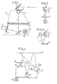
- the device (2) for the production of decorations according to the invention is essentially formed by a housing (8) (in phantom in Figure 1) in which are placed a Fresnel lens (3 ) lit by a torch (4), a lens (5) and a deflection mirror (6).
- the Fresnel lens (3) is placed horizontally in the housing (8) and there is associated with it a horizontal working range (7), the dimensions of which are for example 30 cm ⁇ 30 cm and on which a subject can be placed. whose image projected by this device (2) will constitute the decoration.
- This subject can be formed by a slide, colored filters, or any object, flat or three-dimensional.
- a torch (4) of an electronic flash synchronized with the camera and which may belong to the user, is fixed on the housing (8).
- the light beam emitted by this torch (4), and the path it performs are shown on the drawing by a light ray (1).
- This beam is reflected by a plane mirror (9) on the lens (3). Its rays are refracted by this lens on the objective (5) which poses a focusing device whose main axis coincides with that of the lens and which is placed above the latter.
- This objective (5) gives the subject placed on the working range associated with the lens (3) a real image which is reflected by the reflecting mirror (6), placed above this objective (5), in the field from the camera.
- This mirror (6) is mounted on a pivoting head (10) of the device; can rotate 360 ° around a vertical axis, and can itself rotate around a horizontal axis. The projection can thus be oriented in two directions, one horizontal and the other vertical.
- the objective (5) can be changed, or replaced by a variable focal length objective to vary the size of the projected image.
- the device (2) can also be mounted on casters or placed on a rolling table and its movement towards or away from the photographic field makes it possible to vary the size of the projection.
- the user can thus position and adjust very precisely the image projected on a screen or other.
- a mask of variable shape can be placed on the working area (7) of the lens (3), so as to create areas of light of determined shape; the device (2) then functions as a spotlight.
- Colored filters can also be used with this device (2).
- the pilot lamp (not shown in the drawing) is incorporated into the torch (4) and makes it possible to view the projection obtained with this device outside of the shots.
- a fan (12) is also mounted inside this housing to ensure cooling.
- FIGS 2 and 3 illustrate other embodiments of this device in which the same elements are designated by the same references.
- the torch (4) is placed under the Fresnel lens (3), in its axis.
- the beam which it emits is therefore directed directly onto the lens (3) and does not need to be reflected by a mirror (9).
- the Fresnel lens is replaced by a horizontal Fresnel mirror (13).
- the torch (4) is placed above this mirror (13), and the beam which it emits is directed on this mirror (13) and reflected by it on the objective (5).
- This embodiment of the device has the advantage of minimal bulk.
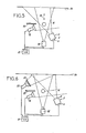
- Figures 4 to 6 show different examples of use of this device (2) for the production of decorations.
- two torches are necessary for a basic installation, one (4) being incorporated into the device (2), and used for projecting the decor onto a surface (14) and the other ( 15) illuminating the subject (16) to be photographed.
- These two torches (4 and 15) are connected to the same flash generator (16), itself connected to the camera (18), in order to be triggered in synchronism, during the shooting.
- a removable mask panel (19) is placed between the torch (15) and the surface (14), so that its light beam does not interfere with that of the torch (15). This panel (19) can more or less hide the torch (4) or be removed depending on the more or less contrasted effect desired.
- the projection device (2) can be moved relative to the subject and to the surface, as illustrated by the double arrows (20 and 21).
- the background is projected both on the subject (16) and on the surface (14). This arrangement makes it possible to obtain very interesting and very varied effects.
- the subject can be placed more or less close to the screen and moved for example in the directions of the double arrow (22).
- the mask panel (19) can be used or not.
- a cardboard mask is placed on the working area (7) of the device (2) so that the projection passes through the subject (16) but without lighting it, the mask then hides the part of the beam illuminating the subject (16).
- FIG. 6 corresponds to that of FIG. 5, in which a third torch (23) is used.
- This torch (23) is connected to the same generator (17) as the other two torches (4 and 15), and illuminates the surface (14) on which the decoration is projected with colored filters (25), which allows d 'significantly increase the effects.
- the mask panel (19) can be used or removed.
- a second generation tor could also be used, to which only the torch (4) would be connected, for example, for projecting the decor.
- the projection power would be considerably increased and it would be possible to project the decor over a large area; in addition there would be a second light source to illuminate the subject (16).
- the result of the projection can be modulated at will. This can be more or less contrasted, colored entirely or partially. and adjusted both in size and in position.
- This device allows photos to be taken with various decorations (portrait, fashion, industry, etc.), access to the working area is easy and allows the projection to be easily composed.
Landscapes
- Physics & Mathematics (AREA)
- General Physics & Mathematics (AREA)
- Projection Apparatus (AREA)
- Overhead Projectors And Projection Screens (AREA)
Applications Claiming Priority (2)
| Application Number | Priority Date | Filing Date | Title |
|---|---|---|---|
| FR8315734A FR2552562B1 (fr) | 1983-09-26 | 1983-09-26 | Dispositif pour la projection de decors pour prises de vues photographiques |
| FR8315734 | 1983-09-26 |
Publications (2)
| Publication Number | Publication Date |
|---|---|
| EP0139600A2 true EP0139600A2 (de) | 1985-05-02 |
| EP0139600A3 EP0139600A3 (de) | 1987-08-05 |
Family
ID=9292765
Family Applications (1)
| Application Number | Title | Priority Date | Filing Date |
|---|---|---|---|
| EP84420159A Withdrawn EP0139600A3 (de) | 1983-09-26 | 1984-09-25 | Hintergrundprojektionsvorrichtung für photographische Aufnahmen |
Country Status (3)
| Country | Link |
|---|---|
| US (1) | US4627697A (de) |
| EP (1) | EP0139600A3 (de) |
| FR (1) | FR2552562B1 (de) |
Families Citing this family (2)
| Publication number | Priority date | Publication date | Assignee | Title |
|---|---|---|---|---|
| US6106124A (en) * | 1996-06-20 | 2000-08-22 | Tarsia; Joseph | Self-contained photo studio lighting apparatus |
| DE102007057272B4 (de) * | 2007-11-27 | 2017-12-28 | Julius von Bismarck | Vorrichtung und Verfahren zur Projektion einer graphischen Darstellung auf eine Projektionsfläche |
Family Cites Families (9)
| Publication number | Priority date | Publication date | Assignee | Title |
|---|---|---|---|---|
| US1224663A (en) * | 1916-02-07 | 1917-05-01 | Bausch & Lomb | Projection apparatus and illumination system therefor. |
| US2718171A (en) * | 1951-08-09 | 1955-09-20 | Harold G Fitzgerald | Image projecting apparatus |
| US3039357A (en) * | 1957-03-11 | 1962-06-19 | Manny Eagle | Photographic assembly and apparatus therefor |
| US3077814A (en) * | 1958-01-27 | 1963-02-19 | Kerkow Herbert | Picture projection and photography |
| US3227509A (en) * | 1962-05-31 | 1966-01-04 | Baker Hobart | Device for projection and photography of backgrounds |
| DE1472288B2 (de) * | 1966-07-06 | 1972-04-20 | Ernst Leitz Gmbh, 6330 Wetzlar | Schreibprojektor |
| US3920323A (en) * | 1973-10-22 | 1975-11-18 | Nihon Kyozu Kabushiki Kaisha | Apparatus for projecting an object |
| US3920320A (en) * | 1974-04-19 | 1975-11-18 | Lumi Tek Inc | Projector for front projection photography |
| DE2651129A1 (de) * | 1976-11-09 | 1978-05-18 | Kindermann & Co Gmbh | Kondensorlinse fuer arbeitsprojektoren |
-
1983
- 1983-09-26 FR FR8315734A patent/FR2552562B1/fr not_active Expired
-
1984
- 1984-09-25 EP EP84420159A patent/EP0139600A3/de not_active Withdrawn
-
1986
- 1986-01-15 US US06/819,987 patent/US4627697A/en not_active Expired - Fee Related
Also Published As
| Publication number | Publication date |
|---|---|
| FR2552562A1 (fr) | 1985-03-29 |
| EP0139600A3 (de) | 1987-08-05 |
| US4627697A (en) | 1986-12-09 |
| FR2552562B1 (fr) | 1988-12-09 |
Similar Documents
| Publication | Publication Date | Title |
|---|---|---|
| US4066885A (en) | Light extractor-diffuser | |
| FR2487993A1 (fr) | Ensemble d'eclairement artificiel pour appareil photographique et reflecteur pour cet ensemble | |
| US3665828A (en) | Background photography | |
| CN2304927Y (zh) | 多用途显像机 | |
| US4183644A (en) | Photographic background device | |
| EP0001951B1 (de) | Projektionsvorrichtung, die die Bildaufnahme eines projizierten Bildes erlaubt | |
| JPH07281257A (ja) | 改良した照明を有する写真遊戯セット | |
| FR2581771A2 (fr) | Appareil de projection et de retroprojection de diapositives avec effet de fondu enchaine | |
| EP0159594B1 (de) | Belichtungsvorrichtung mit hoher Diffusionsfähigkeit | |
| EP0139600A2 (de) | Hintergrundprojektionsvorrichtung für photographische Aufnahmen | |
| US3198097A (en) | Illuminating apparatus | |
| EP0036341B1 (de) | Optisches System zur Erzeugung spezieller Effekte auf Filmen | |
| FR2790061A1 (fr) | Projecteur de lumiere | |
| US3873212A (en) | Optical comparator | |
| JPH0887056A (ja) | 写真撮影用ストロボ装置 | |
| KR200208650Y1 (ko) | 사진 촬영대 | |
| FR2580823A1 (fr) | Dispositif pour la projection de decors notamment pour la realisation de photographies | |
| US6711347B1 (en) | Slide copper system | |
| JP2511625Y2 (ja) | 反射傘内蔵ストロボ | |
| BE900226A (fr) | Artifice photographique. | |
| WO2025120350A1 (fr) | Boîte pour la présentation d'un objet | |
| JP3040127U (ja) | 光軸可変照明装置を有した4色分解カメラ | |
| KR200424192Y1 (ko) | 회전식 다기능 필터가 구비된 카메라용 플래쉬 | |
| US5394218A (en) | Focusing aid for copying cameras | |
| CN1022780C (zh) | 翻拍背景合景摄影方法及其装置 |
Legal Events
| Date | Code | Title | Description |
|---|---|---|---|
| PUAI | Public reference made under article 153(3) epc to a published international application that has entered the european phase |
Free format text: ORIGINAL CODE: 0009012 |
|
| AK | Designated contracting states |
Designated state(s): CH DE GB IT LI |
|
| PUAL | Search report despatched |
Free format text: ORIGINAL CODE: 0009013 |
|
| AK | Designated contracting states |
Kind code of ref document: A3 Designated state(s): CH DE GB IT LI |
|
| 17P | Request for examination filed |
Effective date: 19880205 |
|
| 17Q | First examination report despatched |
Effective date: 19900606 |
|
| STAA | Information on the status of an ep patent application or granted ep patent |
Free format text: STATUS: THE APPLICATION IS DEEMED TO BE WITHDRAWN |
|
| 18D | Application deemed to be withdrawn |
Effective date: 19920331 |