EP0139249A1 - Hot-wire tig welding apparatus - Google Patents
Hot-wire tig welding apparatus Download PDFInfo
- Publication number
- EP0139249A1 EP0139249A1 EP84111468A EP84111468A EP0139249A1 EP 0139249 A1 EP0139249 A1 EP 0139249A1 EP 84111468 A EP84111468 A EP 84111468A EP 84111468 A EP84111468 A EP 84111468A EP 0139249 A1 EP0139249 A1 EP 0139249A1
- Authority
- EP
- European Patent Office
- Prior art keywords
- wire
- current
- hot
- period
- tig welding
- Prior art date
- Legal status (The legal status is an assumption and is not a legal conclusion. Google has not performed a legal analysis and makes no representation as to the accuracy of the status listed.)
- Granted
Links
Images


Classifications
-
- B—PERFORMING OPERATIONS; TRANSPORTING
- B23—MACHINE TOOLS; METAL-WORKING NOT OTHERWISE PROVIDED FOR
- B23K—SOLDERING OR UNSOLDERING; WELDING; CLADDING OR PLATING BY SOLDERING OR WELDING; CUTTING BY APPLYING HEAT LOCALLY, e.g. FLAME CUTTING; WORKING BY LASER BEAM
- B23K9/00—Arc welding or cutting
- B23K9/12—Automatic feeding or moving of electrodes or work for spot or seam welding or cutting
- B23K9/124—Circuits or methods for feeding welding wire
-
- B—PERFORMING OPERATIONS; TRANSPORTING
- B23—MACHINE TOOLS; METAL-WORKING NOT OTHERWISE PROVIDED FOR
- B23K—SOLDERING OR UNSOLDERING; WELDING; CLADDING OR PLATING BY SOLDERING OR WELDING; CUTTING BY APPLYING HEAT LOCALLY, e.g. FLAME CUTTING; WORKING BY LASER BEAM
- B23K9/00—Arc welding or cutting
- B23K9/10—Other electric circuits therefor; Protective circuits; Remote controls
- B23K9/1093—Consumable electrode or filler wire preheat circuits
Definitions
- the present invention relates to a hot-wire TI G welding (i.e. hot-wire inert-gas tungsten arc welding) apparatus and method and, more particularly, to a hot-wire TIG welding power source which is improved to substantially eliminate the magnetic blow of arc, as well as to a controller capable of effecting such a control as to stabilize the melting of the wire when the welding is conducted with the hot-wire TIG welding power source.
- a hot-wire TI G welding i.e. hot-wire inert-gas tungsten arc welding
- Fig. 1 shows a circuit arrangement of an ordinary welding apparatus of hot-wire TIG welding type.
- An arc power source 4 for D.C. welding is connected to a tungsten electrode 2 in a TIG welding torch 1 and to a base metal 3 such that the tungsten electrode constitute a negative electrode, so that an arc 5 is formed in the atmosphere of argon shield gas.
- a wire 6 for welding is fed from a wire feeding device 7 through a conduit 8 and a contact tip 9 connected thereto, so as to be brought into contact with the portion of the base metal 3 in the area where the arc is formed.
- a D.C. or A.C. power source 10 for heating the wire is connected between the contact tip 9 and the base metal 3 so that an electric current flows through the wire 6 to generate a Joule heat thus heating the wire 6 to promote the melting of the wire 6.
- the amount of heat necessary for heating the wire from the room temperature to the melting temperature is a physical value which is determined by the material of the wire in case of neglecting the unavoidable heat loss which is usually rather small.
- the amount of heat is 1270 Joule/g, when the wire is a mild steel. Therefore, the amount of heat necessary for melting the wire is determined if the wire feed speed is given, and the design is made fundamentally on the basis of this heat amount although a slight correction may be required to eliminate the influence of the heat radiated from the arc.
- a wire heating power source of a constant power type capable of supplying a constant power commensurate with the wire feed speed.
- a wire heating power source has not been discussed hitherto as being actually difficult to realize and, as a compromise, a power source of a constant voltage type has been used as the wire heating power source 10, as proposed in the United States Patent No. 3,483,354.
- This power source relies upon a fact that the amount of heat produced in the wire is changed in proportion to the square of the voltage applied and in inverse proportion to the resistance value of the wire (i.e. (Applied voltage) 2 / (Resistance value)).
- the welding method employing such a wire heating power source involves the following problems. Namely, the length Ex of the wire between the end of the contact tip 9 and the base metal (this wire length will be referred to as “extension”, hereinunder) varies momentarily due to vertical oscillation of the welding torch or variation in inclination of the same during the welding.
- the resistance value of the electric lines between the wire heating power source 10 and the contact tip 9 and the base metal is often innegligibly large as compared with the resistance value of the extension Ex of the wire between the contact tip 9 and the base metal 3.
- the welding using a constant voltage type wire heating power source could be carried out satisfactorily only through an aid of manual adjustment of the output voltage of the wire heating power source 10 which is conducted while watching the state of melting of the wire.
- a difference between the demanded heat input and the actual heat input is inevitably caused due to a variation in the resistance value of the wire, setting error of the voltage applied, and so forth.
- this difference does not cause any substantial problem because it is absorbed by the change in the melting position, i.e., the position at which the wire merges in the weld puddle and/or by a plastic deformation of the hot softened end portion of the wire.
- various troubles are experienced such as a stabbing of the base metal by the wire in the rigid state or formation of arc due to separation of the wire end from the base metal as a result of melting of the wire in the state of being short of the feed of the wire. These troubles are quite apt to occur particularly when the wire melting speed is as high as 20 g/min or higher.
- the specification of the United States Patent No. 3,627,974 discloses a hot-wire TIG welding method in which the "magnetic blow" is eliminated by effecting a switching of electric currents such that the electric power supply to the wire is suspended when the arc current is being supplied and the supply of the arc current is suspended when the power is being supplied to the wire.
- This method has not been put into practical use due to lack of stability in the TIG arc.
- the arc current and the wire heating current are supplied alternatingly in a manner shown in Fig. 2.
- the wire heating current Iw is not supplied in the period Tp in which the arc current takes its peak value Iap but the supply of the wire heating current Iw is conducted only in the period Tb in which the arc current takes a base value Iab which is very low, so that the "magnetic blow" is substantially eliminated.
- This hot-wire switching TIG welding method requires a dropper-type power supply employing transistors of large capacities or a chopper-type power supply which also employ transistors of large capacities. These power supplies are generally expensive and large in size.
- Fig. 3 shows an example of the dropper-type power supply for the hot-wire switching TIG welding.
- This power supply is constituted by an arc power source 11 and a wire heating power source 12 which make use of transistors of large capacities in the form of variable resistors for controlling the arc current and the wire heating current, as well as a synchronous controller 13 for effecting the switching of the power supply.
- Fig. 4 shows an example of chopper-type power supply which is large in size and complicated in construction due to the use of transistors of large capacities as the switching elements and the use of reactor and fly-wheel diode for the purpose of current control in the arc power source 14 and the wire heating power source 15.
- This welding method however, still requires a manual adjustment of the output power of the power supply despite the use of the expensive and high-grade power source, because the control relies upon a simple method to maintain the wire heating voltage constant in relation to the wire feeding speed, which method cannot provide delicate automatic control of power when there is caused a difference between the power actually supplied to the extension Ex and the power actually demanded, due to fluctuations of factors such as the length of the extension Ex, time ratio of arc current and wire heating current T p/(Tp + Tb) and so on, with the result that manual control has become necessary during welding in the conventional welding method.
- the present invention aims as its primary object at providing a hot-wire heating control apparatus and method which can optimumly control the wire heating current in response to a wide variation in wire feeding speed and welding conditions, as well as a low cost power supply for hot-wire TIG welding.
- the invention provides a hot-wire heating control apparatus and method in which the actual wire heating electric power is measured from the wire voltage and the wire current and a feedback control is effected such that a wire heating electric power corresponding to the wire feed speed can be obtained.
- the invention provides also a low cost hot-wire switching TIG welding apparatus employing a switching element of a large capacity, by effecting the above-mentioned control of the wire heating electric power through varying the time duration of the supply of the wire heating power only during the period of supply of base arc current.
- the wire melting rate is increased linearly in direct proportion to the wire heating electric power, regardless of the conditions such as the peak values of the currents, time ratio of the current supply, and frequency (4 to 200 Hz), provided that the above-mentioned condition for the heating cycle is met.
- Fig. 6 is a flow chart of a practical example of a wire heating controller in accordance with the invention.
- This arrangement is to realize quite easily a hot-wire TIG welding by a suitable combination of a wire feeding device 6 and a wire heating power source 9 of the type incorporated in the hot-wire TIG welding apparatus schematically shown in Fig. 1.
- the melting of the base metal is basically controlled by varying the TIG arc current while the amount of deposited metal is controlled by adjusting the wire feed speed irrespectively of the arc current.
- the control of the melting of the base metal and the control of the amount of the deposited metal are achieved in a manner which will be explained hereinunder with reference to Fig. 6.
- the operator who conducts the welding inputs a wire feed speed instruction in a step 20, so that the rotation rate of a wire feed motor is controlled in a step 21 to realize the inputted wire feed speed.
- a voltage Vf proportional to the motor speed is determined and this voltage is multiplied in a step 23 by a correction factor which is determined by the diameter and material of the wire, thus obtaining a voltage Pd which is proportional to the required power.
- This voltage is applied as a positive voltage signal to an integrator 27 for the purpose of comparison.
- the momentary value of the wire heating electric power is measured as the product of the wire current Iw and the wire voltage Vw which is detected as the potential difference between the base metal and the contact tip 8, and a voltage Pi proportional to the thus determined momentary heating power is applied as a negative voltage to the integrator 27.
- a voltage Pa in the form of a negative signal is applied to the integrator 27 for making a correction 30 to take into account the influence of the radiation heat of the arc upon the wire.
- the integrator 27 has a time constant which is 3 times or more times larger than the period of switching between the arc current and the wire heating current, and is adapted to supply a control voltage signal 29 to the wire heating power supply 28 such that the value (Pd-Pi) or (Pd-Pi-Pa) standarized by the operation thereof becomes zero.
- a wire heating power commensurate with the wire feed speed is maihtained-automatically.
- the detection of the wire heating electric power is practically effected by applying the magnetic field of the wire current and the wire terminal voltage to a hall device and picking up from the hall device an output voltage proportional to the momentary electric power.
- this wire heating controller can be used in such a way as to effect a feedback control of the output voltage so as to change the electric current supplied to the wire.
- the peak value of the wire current is preferably maintained as low as possible, in order to minimize the magnetic blow of the arc.
- the wire heating controller as shown in Fig. 6 may be used for the purpose of controlling the amplitude of the wire current during the addition of power to the wire, when a hot-wire switching TIG welding power source as shown in Fig. 3 or 4 is used.
- Fig. 7 shows an embodiment of the invention in which the wire heating current has a considerably high level of peak so that the wire heating electric power can be controlled by varying the time duration of supply of the wire heating current.
- a hot-wire switching welding apparatus is constructed by combining a welding power source 4 having a constant-current characteristic as used in ordinary TIG arc welding, gate turn-off thyristors GT031, GT032 as the switching elements of large current, and a wire heating controller 33 in accordance with the invention.
- the wire heating power is detected by a wire power detector 35 which receives both the output from a sensor 36 employing a hall device and the wire voltage.
- a base arc current Iab is set by a base current power source 34 while the peak current Iap of the arc is formed by adding in an overlap state the base current to another current fed from the power source 4.
- a symbol Dl represents a checking diode for preventing inverse flow of electric current so as to separate the wire current circuit from the power source 34.
- the GTO 32 is first turned on so that all part of the output current from the power source 4 is supplied to the wire 6. At a moment Tw thereafter, the GTO 32 is turned on to short- circuit the output current of the power source 4, thus reducing the wire current to 0 (zero). Then, after completion of the base period Tb, both the GTOs 31 and 32 are turned off to resume the initial condition.
- the supply of the base current to the arc 5 is made by the base current power source 34 through the operation of the diode Dl.
- the peak value of the wire heating current is almost equal to the arc current, so that the wire heating electric power is controlled through the control of time duration of supply of the wire heating current.
- the GTO 31 and GTO 32 are controlled to realize a time duration Tw of electric power supply to the wire which time duration Tw is determined to provide an electric power which is commensurate with the wire feed speed, by making use of the wire heating controller 33 of the invention while taking into account the output signal from the wire heating electric power detector 35.
- Fig. 9 shows a circuit arrangement of a hot-wire switching TIG welding which employs a more simplified form of the circuit than that shown in Fig. 7.
- the switching frequency of the arc is high, the period of supply of base current is correspondingly short, but the arc is sufficiently stabilized even when the base current power source 34 and the diode Dl shown in Fig. 7 are removed, provided that the period of supply of base current is about 50 ms or shorter. This is because the tungsten electrode can be maintained at temperatures high enough to maintain the emission of the thermoelectron with the result that re- arcing is readily possible.
- the arc receives a voltage which is the sum of the wire voltage between the contact tip 9 and the base metal 3 and the voltage drop across the GTO 31 or, when the GTO 32 has been turned on, the voltage drop across the GTO 32. In this case, therefore, a base current not greater than 50A flows in the period Tb of the base current. In order to prevent any excessive rise of the arc current during in the period of supply of the base current, it is necessary that the wire voltage be maintained at 9V or less.
- Fig. 10 schematically shows the waveform of electric current used in a low-pulse TIG welding conducted by means of the circuit as shown in Fig. 9.
- Table 3 shows the conditions of welding employed in this embodiment of the invention.
- the low-pulse (that is, the cycle of repetition of T LOW and THIGH shown in Fig. 10 is low) current is supplied by a welding power source 4 in the circuit as shown in Fig. 7 and this output from the power source 4 is supplied alternatingly to the arc and the wire by means of the GTOs 31 and 32 explained in Fig. 8.
- the detection of the wire heating electric power is conducted by using a wire heating electric power detector 35 and the time duration Tw of supply of the wire heating current is determined and controlled in such a manner as to provide the wire heating electric power which is commensurate with the wire feeding speed.
- the time duration Tw (shown in Fig. 10) of the supply of the wire heating power is longer than that in the high peak current period. Due to the reasons stated above, according to the invention, the wire can be continuously heated and melted advantageously even when the welding is conducted by low-pulse TIG welding with a constant wire feed speed.
- the period of peak arc current is 60% of the whole period of arc current supply, it is possible to obtain a practically satisfactory wire melting rate of 20 g/min even in the LOW peak current period as will be seen from Table 3, provided that the mean arc current throughout the LOW peak current period is at least 120A.
- the switching frequency of the hot-wire switching TIG is made too low, the cycle of switching undesirably disturbs the periodical solidification of the molten metal which takes place by a phenomenon called "lapping effect" which periodical solidification is brought about by the application of the low pulse.
- the switching frequency of the hot-wire switching TIG In order to ensure an attractive appearance of the weld bead through elimination of the lapping effect, it has been necessary to select the switching frequency of the hot-wire switching TIG to be on the order-of 10 Hz or higher.
- the cycle of the low-pulse repetition is 5 Hz or higher, the periodical solidification can not be obtained satisfactorily due to thermalinertia of the molten metal, so that the solidification state becomes not different from that of continuous solidification, thus nullifying the merit of the use of the low pulse repetition. Therefore, the use of the switching current waveform as shown in Fig. 10 produces a remarkable effect only when the frequency of the repetition of the low-pulse is 4 Hz or lower.
- Fig. 11 shows a circuit in which the GTO 32 has been removed from the circuit as shown in Fig. 9.
- the output current from the arc power source 4 is made to branch to the wire 6 as the GTO 31 is turned on, with the result that the arc current is decreased and forcibly becomes one in the period of the base current.
- the period of supply of the electric power to the wire is determined and controlled by the wire heating controller 33 which operates with reference to the output signal from the wire heating electric power detector 35.
- the state of melting of the base metal 3 is generally determined by the mean arc current. In this case, therefore, the arc current is detected by means of a flow diverter 37 and the output of the arc current power source 4 is controlled such that the mean value of the arc current is maintained constant.
- circuits shown in Figs. 7, 9 and 11 brings about such advantage that a relatively low cost hot-wire switching can be obtained by adding a switching unit composed of low cost large-current switching elements such as GTO to a conventionally used low cost welding power supply for TIG welding.
- a switching unit composed of low cost large-current switching elements such as GTO
- these circuits cannot provide a wire melting rate exceeding 40 g/min because the wire voltage Vw is limited to 9V or lower.
- Fig. 13 shows an arrangement in which the arc power source and the hot-wire heating power source are provided separately.
- the arc power source is constructed by an ordinary arc power source 4 for TIG welding and a GTO 40 connected to the output terminal of the arc power source 4 in parallel with the arc 5.
- the wire heating power source is constituted by a constant-voltage type welding power source 41 with a GTO 42 being connected to the output terminal thereof in series to the wire 6 which is the load.
- the peak period and base period of the arc current are determined by turning on-and-off of the GTO 40.
- the controller 43 controls the on-period of the GTO 42 within the base period such that a wire heating electric power commensurate with.the wire feed speed Vf is obtained.
- a wire heating electric power commensurate with.the wire feed speed Vf is obtained.
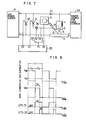
- Fig. 14 shows another embodiment of the invention which employs a control of the time duration of the supply of the wire heating current in such a way as to provide a wire heating electric power commensurate with the wire feed speed.
- This embodiment employs quite a low cost wire heating power source 56 equipped with a transformer TR having a TRIAC (triode A.C. switch) 54 in the primary side thereof.
- the TIG arc 5 was formed by a commercially available low-pulse TIG power source 51.
- the base period of the arc is detected by a base period detector 53 which receives the signal from a arc current detector 52, and the TRIAC 54 is turned on by the control signal providing device 55 only during the base period.
- the wire feed speed controller 57 is adapted to control the wire feed speed and to deliver to a wire heating power controller 58 a voltage Vf proportional to the wire feed speed.
- the wire heating power controller 58 is adapted to control the phase of electric power supply to the TRIAC 54 by comparing the output signal from the wire heating power detector 35 and the voltage Vf proportional to the wire feed speed.
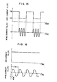
- Fig. 15 shows the waveform of the output current from this circuit.
- the control signal providing device 55 of the TRIAC 54 employs the same number of positive half waves and negative half waves, and the power supply to the wire is made only during the base period.
- a high wire melting rate of 40 g/min was obtained by this welding apparatus.
- the arc welding could be executed without substantial problem even by continuous supply of arc current and wire heating current as shown in Fig. 16. This will be attributable to the following fact.
- Fig. 17 shows still another embodiment of the invention, in which rectifiers 59, 60 are provided at the secondary side of a transformer for a wire heating power source as shown in Fig. 14 so as to effect full wave rectification regarding the output power for wire heating current.
- rectifiers 59, 60 are provided at the secondary side of a transformer for a wire heating power source as shown in Fig. 14 so as to effect full wave rectification regarding the output power for wire heating current.
Landscapes
- Engineering & Computer Science (AREA)
- Physics & Mathematics (AREA)
- Plasma & Fusion (AREA)
- Mechanical Engineering (AREA)
- Arc Welding In General (AREA)
- Arc Welding Control (AREA)
Abstract
Description
- The present invention relates to a hot-wire TIG welding (i.e. hot-wire inert-gas tungsten arc welding) apparatus and method and, more particularly, to a hot-wire TIG welding power source which is improved to substantially eliminate the magnetic blow of arc, as well as to a controller capable of effecting such a control as to stabilize the melting of the wire when the welding is conducted with the hot-wire TIG welding power source.
- Fig. 1 shows a circuit arrangement of an ordinary welding apparatus of hot-wire TIG welding type.
- An
arc power source 4 for D.C. welding is connected to atungsten electrode 2 in a TIG welding torch 1 and to a base metal 3 such that the tungsten electrode constitute a negative electrode, so that anarc 5 is formed in the atmosphere of argon shield gas. Awire 6 for welding is fed from awire feeding device 7 through a conduit 8 and acontact tip 9 connected thereto, so as to be brought into contact with the portion of the base metal 3 in the area where the arc is formed. A D.C. orA.C. power source 10 for heating the wire is connected between thecontact tip 9 and the base metal 3 so that an electric current flows through thewire 6 to generate a Joule heat thus heating thewire 6 to promote the melting of thewire 6. - In this welding method, the amount of heat necessary for heating the wire from the room temperature to the melting temperature is a physical value which is determined by the material of the wire in case of neglecting the unavoidable heat loss which is usually rather small. For example, the amount of heat is 1270 Joule/g, when the wire is a mild steel. Therefore, the amount of heat necessary for melting the wire is determined if the wire feed speed is given, and the design is made fundamentally on the basis of this heat amount although a slight correction may be required to eliminate the influence of the heat radiated from the arc.
- Ideally, therefore, it is preferred to use a wire heating power source of a constant power type, capable of supplying a constant power commensurate with the wire feed speed. Such a wire heating power source, however, has not been discussed hitherto as being actually difficult to realize and, as a compromise, a power source of a constant voltage type has been used as the wire
heating power source 10, as proposed in the United States Patent No. 3,483,354. This power source relies upon a fact that the amount of heat produced in the wire is changed in proportion to the square of the voltage applied and in inverse proportion to the resistance value of the wire (i.e. (Applied voltage)2/ (Resistance value)). - The welding method employing such a wire heating power source, however, involves the following problems. Namely, the length Ex of the wire between the end of the
contact tip 9 and the base metal (this wire length will be referred to as "extension", hereinunder) varies momentarily due to vertical oscillation of the welding torch or variation in inclination of the same during the welding. In addition, the resistance value of the electric lines between the wireheating power source 10 and thecontact tip 9 and the base metal is often innegligibly large as compared with the resistance value of the extension Ex of the wire between thecontact tip 9 and the base metal 3. For these reasons, the welding using a constant voltage type wire heating power source could be carried out satisfactorily only through an aid of manual adjustment of the output voltage of the wireheating power source 10 which is conducted while watching the state of melting of the wire. - A difference between the demanded heat input and the actual heat input is inevitably caused due to a variation in the resistance value of the wire, setting error of the voltage applied, and so forth. When this difference is relatively small, this difference does not cause any substantial problem because it is absorbed by the change in the melting position, i.e., the position at which the wire merges in the weld puddle and/or by a plastic deformation of the hot softened end portion of the wire. However, when this difference becomes relatively large, various troubles are experienced such as a stabbing of the base metal by the wire in the rigid state or formation of arc due to separation of the wire end from the base metal as a result of melting of the wire in the state of being short of the feed of the wire. These troubles are quite apt to occur particularly when the wire melting speed is as high as 20 g/min or higher.
- It is known that, in hot-wire TIG welding, a magnetic interference is caused between the wire heating current and the arc current, particularly when the wire heating current is increased, resulting in a disturbance in the arc due to a phenomenon called "magnetic blow" hindering the welding undesirably.
- As a countermeasure for obviating this problem, the specification of the United States Patent No. 3,627,974 discloses a hot-wire TIG welding method in which the "magnetic blow" is eliminated by effecting a switching of electric currents such that the electric power supply to the wire is suspended when the arc current is being supplied and the supply of the arc current is suspended when the power is being supplied to the wire. This method, however, has not been put into practical use due to lack of stability in the TIG arc. In another proposal referred to as "hot- wise switching TIG welding method", the arc current and the wire heating current are supplied alternatingly in a manner shown in Fig. 2. More specifically, in this method, the wire heating current Iw is not supplied in the period Tp in which the arc current takes its peak value Iap but the supply of the wire heating current Iw is conducted only in the period Tb in which the arc current takes a base value Iab which is very low, so that the "magnetic blow" is substantially eliminated. This hot-wire switching TIG welding method, however, requires a dropper-type power supply employing transistors of large capacities or a chopper-type power supply which also employ transistors of large capacities. These power supplies are generally expensive and large in size. Fig. 3 shows an example of the dropper-type power supply for the hot-wire switching TIG welding. This power supply is constituted by an arc power source 11 and a wire
heating power source 12 which make use of transistors of large capacities in the form of variable resistors for controlling the arc current and the wire heating current, as well as asynchronous controller 13 for effecting the switching of the power supply. On the other hand, Fig. 4 shows an example of chopper-type power supply which is large in size and complicated in construction due to the use of transistors of large capacities as the switching elements and the use of reactor and fly-wheel diode for the purpose of current control in thearc power source 14 and the wireheating power source 15. - This welding method, however, still requires a manual adjustment of the output power of the power supply despite the use of the expensive and high-grade power source, because the control relies upon a simple method to maintain the wire heating voltage constant in relation to the wire feeding speed, which method cannot provide delicate automatic control of power when there is caused a difference between the power actually supplied to the extension Ex and the power actually demanded, due to fluctuations of factors such as the length of the extension Ex, time ratio of arc current and wire heating current Tp/(Tp + Tb) and so on, with the result that manual control has become necessary during welding in the conventional welding method.
- In view of the above, the present invention aims as its primary object at providing a hot-wire heating control apparatus and method which can optimumly control the wire heating current in response to a wide variation in wire feeding speed and welding conditions, as well as a low cost power supply for hot-wire TIG welding.
- Briefly, the invention provides a hot-wire heating control apparatus and method in which the actual wire heating electric power is measured from the wire voltage and the wire current and a feedback control is effected such that a wire heating electric power corresponding to the wire feed speed can be obtained. The invention provides also a low cost hot-wire switching TIG welding apparatus employing a switching element of a large capacity, by effecting the above-mentioned control of the wire heating electric power through varying the time duration of the supply of the wire heating power only during the period of supply of base arc current.
-
- Fig. 1 is an illustration of a conventional ordinary hot-wire TIG welding apparatus;
- Fig. 2 is an illustration of the principle of conventional hot-wire TIG welding methods as a prior art;
- Figs. 3 and 4 are illustrations of a conventional hot-wire TIG welding apparatus as a prior art;
- Fig. 5 shows a result of an experiment conducted to examine the relationship between the wire heating electric power and the wire melting rate in hot-wire TIG welding;
- Fig. 6 is a flow chart showing the arrangement of the wire heating controller in accordance with the invention;
- Fig. 7 is an illustration of a hot-wire switching TIG welding apparatus of the invention;
- Fig. 8 is an illustration.of the operation of the hot-wire TIG welding apparatus shown in Fig. 7;
- Fig. 9 shows another example of hot-wire TIG welding apparatus in accordance with the invention;
- Fig. 10 is an illustration of an embodiment of the invention;
- Fig. 11 shows another example of a hot-wire switching TIG welding apparatus in accordance with the invention;
- Fig. 12 is an illustration of the operation of .the apparatus shown in Fig. ll;
- Fig. 13 is an illustration of an embodiment of the invention;
- Fig. 14 is another example of the hot-wire switching TIG welding apparatus in accordance with the invention;
- Fig. 15 is an illustration of the operation of the welding apparatus shown in Fig. 14; and
- Fig. 16 is a chart showing waveforms of electric currents, for illustrating the operation of still another example of the welding apparatus of the invention.
- Fig. 17 is still another example of the hot-wire switching TIG welding apparatus embodying the invention.
- An experiment was conducted to examine the relationship between the wire heating electric power and the wire melting rate, by applying the wire heating current in the form of pulses of waveform as shown in Fig. 2 to a mild steel wire of 1.2 mm dia., without supplying the arc current. The result of this experiment is shown in Fig. 5. When a point on the wire is subjected to 4 or more consecutive heating current cycles before this point travels through the length of the wire extension Ex, the condition of heating of the wire can be regarded materially as being a continuous heating. It was confirmed that the wire melting rate is increased linearly in direct proportion to the wire heating electric power, regardless of the conditions such as the peak values of the currents, time ratio of the current supply, and frequency (4 to 200 Hz), provided that the above-mentioned condition for the heating cycle is met.
- Fig. 6 is a flow chart of a practical example of a wire heating controller in accordance with the invention.
- This arrangement is to realize quite easily a hot-wire TIG welding by a suitable combination of a
wire feeding device 6 and a wireheating power source 9 of the type incorporated in the hot-wire TIG welding apparatus schematically shown in Fig. 1. In the hot-wire TIG welding, it is desirable that the melting of the base metal is basically controlled by varying the TIG arc current while the amount of deposited metal is controlled by adjusting the wire feed speed irrespectively of the arc current. According to the invention, the control of the melting of the base metal and the control of the amount of the deposited metal are achieved in a manner which will be explained hereinunder with reference to Fig. 6. - Referring to Fig. 6, as the first step of the operation, the operator who conducts the welding inputs a wire feed speed instruction in a
step 20, so that the rotation rate of a wire feed motor is controlled in astep 21 to realize the inputted wire feed speed. Then, in astep 22, a voltage Vf proportional to the motor speed is determined and this voltage is multiplied in astep 23 by a correction factor which is determined by the diameter and material of the wire, thus obtaining a voltage Pd which is proportional to the required power. This voltage is applied as a positive voltage signal to anintegrator 27 for the purpose of comparison. On the other hand, the momentary value of the wire heating electric power is measured as the product of the wire current Iw and the wire voltage Vw which is detected as the potential difference between the base metal and the contact tip 8, and a voltage Pi proportional to the thus determined momentary heating power is applied as a negative voltage to theintegrator 27. When a more delicate control is required, a voltage Pa in the form of a negative signal is applied to theintegrator 27 for making acorrection 30 to take into account the influence of the radiation heat of the arc upon the wire. - The
integrator 27 has a time constant which is 3 times or more times larger than the period of switching between the arc current and the wire heating current, and is adapted to supply acontrol voltage signal 29 to the wireheating power supply 28 such that the value (Pd-Pi) or (Pd-Pi-Pa) standarized by the operation thereof becomes zero. As a result of this feedback control of the output voltage from thewire heating source 28, a wire heating power commensurate with the wire feed speed is maihtained-automatically. The detection of the wire heating electric power is practically effected by applying the magnetic field of the wire current and the wire terminal voltage to a hall device and picking up from the hall device an output voltage proportional to the momentary electric power. - When a D.C. wire
heating power source 10 as shown in Fig. 1 is used, this wire heating controller can be used in such a way as to effect a feedback control of the output voltage so as to change the electric current supplied to the wire. In this ordinary hot-wire TIG welding, the peak value of the wire current is preferably maintained as low as possible, in order to minimize the magnetic blow of the arc. The wire heating controller as shown in Fig. 6 may be used for the purpose of controlling the amplitude of the wire current during the addition of power to the wire, when a hot-wire switching TIG welding power source as shown in Fig. 3 or 4 is used. - It is to be noted, however, a practical power source of a much reduced cost can be realized by making an effective use of the characteristic feature of the hot-wire switching TIG welding power supply. Namely, in the case of the hot-wire switching TIG welding, the addition of power to the wire is conducted only in the period of supply of base arc current. Therefore, even if the wire heating current is increased to such a peak level as causing the tendency of the magnetic blow, no substantially intolerable influence is caused because the arc current in this base arc current period is so small as not to materially affect the rate of melting of the base material. Thus, in the hot-wire switching TIG welding, the peak value of the wire heating current does not materially affect the welding operation and, therefore, the welding can be conducted with a sufficiently high level of peak of the wire heating current.
- Fig. 7 shows an embodiment of the invention in which the wire heating current has a considerably high level of peak so that the wire heating electric power can be controlled by varying the time duration of supply of the wire heating current. More specifically, in this embodiment, a hot-wire switching welding apparatus is constructed by combining a
welding power source 4 having a constant-current characteristic as used in ordinary TIG arc welding, gate turn-off thyristors GT031, GT032 as the switching elements of large current, and awire heating controller 33 in accordance with the invention. The wire heating power is detected by awire power detector 35 which receives both the output from asensor 36 employing a hall device and the wire voltage. A base arc current Iab is set by a basecurrent power source 34 while the peak current Iap of the arc is formed by adding in an overlap state the base current to another current fed from thepower source 4. A symbol Dl represents a checking diode for preventing inverse flow of electric current so as to separate the wire current circuit from thepower source 34. This apparatus operates in a manner explained hereinunder with reference to Fig. 8. Namely, in the period Tp in which the peak current is applied, theGTO 31 andGTO 32 are turned off so that the peak arc current Iap flows between thetungsten electrode 2 and the base metal 3. However, when the period Tb in which only te base current is supplied is commenced, theGTO 32 is first turned on so that all part of the output current from thepower source 4 is supplied to thewire 6. At a moment Tw thereafter, theGTO 32 is turned on to short- circuit the output current of thepower source 4, thus reducing the wire current to 0 (zero). Then, after completion of the base period Tb, both theGTOs arc 5 is made by the basecurrent power source 34 through the operation of the diode Dl. In this case, since thepower source 4 of constant-current type is used, the peak value of the wire heating current is almost equal to the arc current, so that the wire heating electric power is controlled through the control of time duration of supply of the wire heating current. Namely, in this case, theGTO 31 andGTO 32 are controlled to realize a time duration Tw of electric power supply to the wire which time duration Tw is determined to provide an electric power which is commensurate with the wire feed speed, by making use of thewire heating controller 33 of the invention while taking into account the output signal from the wire heatingelectric power detector 35. When the wire voltage Vw in the extension Ex of the wire between thecontact tip 9 and the base metal 3 is higher than 9V, the incidental electric current is supplied to the arc even from thearc power source 4 so that the control of the base arc current becomes difficult. The wire voltage exceeds 9V, when a wire melting rate of is not less than 40 g/min in a case of about 30 mm regarding the extension Ex value. Thus, when the wire melting rate is less than 40 g/min, this embodiment can be used practically satisfactorily. Table 1 shows an example of conditions of welding conducted -by the described embodiment of the welding apparatus. - Fig. 9 shows a circuit arrangement of a hot-wire switching TIG welding which employs a more simplified form of the circuit than that shown in Fig. 7. When the switching frequency of the arc is high, the period of supply of base current is correspondingly short, but the arc is sufficiently stabilized even when the base
current power source 34 and the diode Dl shown in Fig. 7 are removed, provided that the period of supply of base current is about 50 ms or shorter. This is because the tungsten electrode can be maintained at temperatures high enough to maintain the emission of the thermoelectron with the result that re- arcing is readily possible. However, if the basecurrent power source 34 and the diode Dl are removed, the arc receives a voltage which is the sum of the wire voltage between thecontact tip 9 and the base metal 3 and the voltage drop across theGTO 31 or, when theGTO 32 has been turned on, the voltage drop across theGTO 32. In this case, therefore, a base current not greater than 50A flows in the period Tb of the base current. In order to prevent any excessive rise of the arc current during in the period of supply of the base current, it is necessary that the wire voltage be maintained at 9V or less. - A method called low-pulse TIG welding method is used in order to prevent any dripping of the molten metal in, for example, all-position welding on a fixed pipe. Fig. 10 schematically shows the waveform of electric current used in a low-pulse TIG welding conducted by means of the circuit as shown in Fig. 9. Table 3 shows the conditions of welding employed in this embodiment of the invention. The low-pulse (that is, the cycle of repetition of TLOW and THIGH shown in Fig. 10 is low) current is supplied by a
welding power source 4 in the circuit as shown in Fig. 7 and this output from thepower source 4 is supplied alternatingly to the arc and the wire by means of theGTOs electric power detector 35 and the time duration Tw of supply of the wire heating current is determined and controlled in such a manner as to provide the wire heating electric power which is commensurate with the wire feeding speed. When the wire is fed at a constant speed, since the peak value Iwp of the wire current in the LOW peak current period is low, the time duration Tw (shown in Fig. 10) of the supply of the wire heating power is longer than that in the high peak current period. Due to the reasons stated above, according to the invention, the wire can be continuously heated and melted advantageously even when the welding is conducted by low-pulse TIG welding with a constant wire feed speed. If the period of peak arc current is 60% of the whole period of arc current supply, it is possible to obtain a practically satisfactory wire melting rate of 20 g/min even in the LOW peak current period as will be seen from Table 3, provided that the mean arc current throughout the LOW peak current period is at least 120A. In the case of the application of the low-pulse to the hot-wire switching TIG welding, if the switching frequency of the hot-wire switching TIG is made too low, the cycle of switching undesirably disturbs the periodical solidification of the molten metal which takes place by a phenomenon called "lapping effect" which periodical solidification is brought about by the application of the low pulse. In order to ensure an attractive appearance of the weld bead through elimination of the lapping effect, it has been necessary to select the switching frequency of the hot-wire switching TIG to be on the order-of 10 Hz or higher. On the other hand, when the cycle of the low-pulse repetition is 5 Hz or higher, the periodical solidification can not be obtained satisfactorily due to thermalinertia of the molten metal, so that the solidification state becomes not different from that of continuous solidification, thus nullifying the merit of the use of the low pulse repetition. Therefore, the use of the switching current waveform as shown in Fig. 10 produces a remarkable effect only when the frequency of the repetition of the low-pulse is 4 Hz or lower. In the case, therefore, it suffices only to produce the low-pulse current from awelding power source 4 in the circuit as shown in Fig. 9. It is possible to obtain a practically sufficient wire melting rate of 20 g/min even in the LOW peak current period, provided that the mean arc current in the LOW peak current period is about 120 A or greater. In some case, the shape of the bead is impaired if the wire is fed at an same speed during the LOW peak current period. In such case, it is advisable to conduct a so-called "pulse-feed" in which the wire feed speed is reduced in the LOW period. In this pulse feed, needless to say, the wire heating electric power is varied in accordance with variation in the wire feed speed. - Fig. 11 shows a circuit in which the
GTO 32 has been removed from the circuit as shown in Fig. 9. In this case, the output current from thearc power source 4 is made to branch to thewire 6 as theGTO 31 is turned on, with the result that the arc current is decreased and forcibly becomes one in the period of the base current. The period of supply of the electric power to the wire is determined and controlled by thewire heating controller 33 which operates with reference to the output signal from the wire heatingelectric power detector 35. The state of melting of the base metal 3 is generally determined by the mean arc current. In this case, therefore, the arc current is detected by means of aflow diverter 37 and the output of the arccurrent power source 4 is controlled such that the mean value of the arc current is maintained constant. Fig. 12-shows the waveform of output current from the circuit shown in Fig. ll. It is possible to control the period Tw of power supply to the wire while fixing the switching period T. Alternatively, it is also possible to control the period Tw while fixing the peak current period Tp of the arc current. - The circuits shown in Figs. 7, 9 and 11 brings about such advantage that a relatively low cost hot-wire switching can be obtained by adding a switching unit composed of low cost large-current switching elements such as GTO to a conventionally used low cost welding power supply for TIG welding. Unfortunately, however, these circuits cannot provide a wire melting rate exceeding 40 g/min because the wire voltage Vw is limited to 9V or lower.
- Fig. 13 shows an arrangement in which the arc power source and the hot-wire heating power source are provided separately. In this case, the arc power source is constructed by an ordinary
arc power source 4 for TIG welding and aGTO 40 connected to the output terminal of thearc power source 4 in parallel with thearc 5. On the other hand, the wire heating power source is constituted by a constant-voltage type weldingpower source 41 with aGTO 42 being connected to the output terminal thereof in series to thewire 6 which is the load. The peak period and base period of the arc current are determined by turning on-and-off of theGTO 40. Making reference to the output signal from the wireheating power detector 35, thecontroller 43 controls the on-period of theGTO 42 within the base period such that a wire heating electric power commensurate with.the wire feed speed Vf is obtained. According to this arrangement, it is possible to control the wire heating current and the are current independently of each other. In a case of such constitution, a high wire melting rate of 100 g/min could be obtained by using a rather high voltage of wireheating power source 41 such as 20V or so. - Fig. 14 shows another embodiment of the invention which employs a control of the time duration of the supply of the wire heating current in such a way as to provide a wire heating electric power commensurate with the wire feed speed. This embodiment employs quite a low cost wire
heating power source 56 equipped with a transformer TR having a TRIAC (triode A.C. switch) 54 in the primary side thereof. TheTIG arc 5 was formed by a commercially available low-pulseTIG power source 51. The base period of the arc is detected by abase period detector 53 which receives the signal from a arccurrent detector 52, and theTRIAC 54 is turned on by the controlsignal providing device 55 only during the base period. The wirefeed speed controller 57 is adapted to control the wire feed speed and to deliver to a wire heating power controller 58 a voltage Vf proportional to the wire feed speed. The wireheating power controller 58 is adapted to control the phase of electric power supply to theTRIAC 54 by comparing the output signal from the wireheating power detector 35 and the voltage Vf proportional to the wire feed speed. Fig. 15 shows the waveform of the output current from this circuit. In order to prevent magnetic flux from being distributed locally regarding the transformer TR in the wireheating power source 56, the controlsignal providing device 55 of theTRIAC 54 employs the same number of positive half waves and negative half waves, and the power supply to the wire is made only during the base period. A high wire melting rate of 40 g/min was obtained by this welding apparatus. In the case of a low wire melting rate of 10 g/min, the arc welding could be executed without substantial problem even by continuous supply of arc current and wire heating current as shown in Fig. 16. This will be attributable to the following fact. - Namely, when the supply of electric current to the wire is made through the TRIAC, although the "magnetic blow" occurs, the arc returns to the position just under the
tungsten electrode 2 at interval of a pause of power supply existing per every half cycle. It was confirmed that a high rigidity of the arc can be obtained as compared with the heating of the wire by a mere D.C. or A.C. current, when the above-mentioned interval of the pause of power supply is π/4 radian or greater. - Fig. 17 shows still another embodiment of the invention, in which rectifiers 59, 60 are provided at the secondary side of a transformer for a wire heating power source as shown in Fig. 14 so as to effect full wave rectification regarding the output power for wire heating current. In the constitution shown in Fig. 14 there is caused such a case that current flows from the
wire 6 to the tungsten,electrode 2 if the wire is not in contact with the base material. However, as shown in Fig. 17, if the rectifiers 59, 60 are disposed such that the voltage polarity at the side of the wire conforms to the voltage polarity at the side of atungsten electrode 2, there is obtained such effect that current is prevented from flowing from thewire 6 to thetungsten electrode 2 when the wire is not in contact with the base material. - Although the invention has been described through specific embodiments in-which elements of GTO are used as the large-current switching means, these GTO elements can be obviously substituted by large-current transistors. It will be obvious also that the TRIAC used as the A.C. switching element can be substituted by an SCR (thyrister) connected in an inversed parallel manner (that is, disposition in paral- el while reversing the direction of the flow of current).
- The invention offers the following advantages:
- 1. According to the invention, low cost and small- sized electronic circuits are realized for the detection of the electric power and the power control, so that the heating of the hot wire can be controlled without any dependency on the waveform and peak value of the current and voltage of the electric power for heating the wire. This in turn permits the use of switching elements which handle large electric and provides various practical measures for reducing the cost and size of hot-wire switching TIG welding power source which hitherto has been generally expensive and large in size. For instance, in the circuit shown in Fig. 9, a hot-wire switching TIG welding apparatus could be obtained merely by adding a simple GTO switching unit to a conventional TIG power source.
- 2. Since a wire heating electric power commensurate with the wire feed speed is always obtained, the operator can change the wire feeding speed as desired without making any additional adjustment of the wire heating current.
- 3. Changes in the factors during the welding, such as a change in the length of the extension Ex, a resulting change in the resistance value of the wire, and a change in the voltage drop in the electric lines between the power source and the
contact tip 9 can be automatically compensated for, so that the welding can be conducted with a high stability. In addition, undesirable leaving of a solid softened wire in the weld metal, which has been often experienced in the conventional hot-wire TIG welding particularly when the wire heating power is relatively small in comparison with the wire feed speed, can be eliminated almost perfectly.


Claims (19)
Applications Claiming Priority (10)
| Application Number | Priority Date | Filing Date | Title |
|---|---|---|---|
| JP17712583A JPS6072669A (en) | 1983-09-27 | 1983-09-27 | Control device for hot wire switching tig welding |
| JP177125/83 | 1983-09-27 | ||
| JP177124/83 | 1983-09-27 | ||
| JP17712483A JPS6072668A (en) | 1983-09-27 | 1983-09-27 | Hot wire switching tig welding device |
| JP186998/83 | 1983-10-07 | ||
| JP58186998A JPS6082278A (en) | 1983-10-07 | 1983-10-07 | Hot wire tig welding device |
| JP11310684A JPH0615107B2 (en) | 1984-06-04 | 1984-06-04 | Welding equipment |
| JP113106/84 | 1984-06-04 | ||
| JP135071/84 | 1984-07-02 | ||
| JP59135071A JPH0679781B2 (en) | 1984-07-02 | 1984-07-02 | Hot wire TIG welding equipment |
Publications (2)
| Publication Number | Publication Date |
|---|---|
| EP0139249A1 true EP0139249A1 (en) | 1985-05-02 |
| EP0139249B1 EP0139249B1 (en) | 1990-05-02 |
Family
ID=27526583
Family Applications (1)
| Application Number | Title | Priority Date | Filing Date |
|---|---|---|---|
| EP84111468A Expired - Lifetime EP0139249B1 (en) | 1983-09-27 | 1984-09-26 | Hot-wire tig welding apparatus |
Country Status (3)
| Country | Link |
|---|---|
| EP (1) | EP0139249B1 (en) |
| KR (1) | KR900000712B1 (en) |
| DE (1) | DE3482097D1 (en) |
Cited By (6)
| Publication number | Priority date | Publication date | Assignee | Title |
|---|---|---|---|---|
| EP0194045A2 (en) * | 1985-02-13 | 1986-09-10 | Babcock-Hitachi Kabushiki Kaisha | Semi-automatic hot wire tig welding equipment |
| EP0247628A2 (en) * | 1986-05-30 | 1987-12-02 | Babcock-Hitachi Kabushiki Kaisha | Method of control and apparatus for hot-wire welding |
| EP0316936A2 (en) * | 1987-11-19 | 1989-05-24 | Babcock-Hitachi Kabushiki Kaisha | AC tig welding apparatus using hot wire |
| DE102006047107A1 (en) * | 2006-09-27 | 2008-04-03 | Lorch Schweißtechnik GmbH | welding machine |
| CN115659127A (en) * | 2022-11-21 | 2023-01-31 | 苏芯物联技术(南京)有限公司 | Welding process parameter solving method under optimal wire using cost |
| EP4410466A1 (en) * | 2023-01-25 | 2024-08-07 | Daihen Corporation | Submerged arc welding method and submerged arc welding machine |
Families Citing this family (1)
| Publication number | Priority date | Publication date | Assignee | Title |
|---|---|---|---|---|
| EP2644306A1 (en) | 2012-03-28 | 2013-10-02 | Siegfried Plasch | Welding device and control method for a welding process |
Citations (2)
| Publication number | Priority date | Publication date | Assignee | Title |
|---|---|---|---|---|
| US3483354A (en) * | 1965-03-01 | 1969-12-09 | Union Carbide Corp | Method for depositing metal with a tig arc |
| US3627974A (en) * | 1969-05-09 | 1971-12-14 | Air Reduction | Avoidance of current interference in consumable contact hot wire arc welding |
-
1984
- 1984-09-26 KR KR1019840005903A patent/KR900000712B1/en not_active IP Right Cessation
- 1984-09-26 DE DE8484111468T patent/DE3482097D1/en not_active Expired - Lifetime
- 1984-09-26 EP EP84111468A patent/EP0139249B1/en not_active Expired - Lifetime
Patent Citations (2)
| Publication number | Priority date | Publication date | Assignee | Title |
|---|---|---|---|---|
| US3483354A (en) * | 1965-03-01 | 1969-12-09 | Union Carbide Corp | Method for depositing metal with a tig arc |
| US3627974A (en) * | 1969-05-09 | 1971-12-14 | Air Reduction | Avoidance of current interference in consumable contact hot wire arc welding |
Non-Patent Citations (3)
| Title |
|---|
| PATENT ABSTRACTS OF JAPAN, vol. 7, no. 187, 16th August 1983, page (M-236)(1332); JP-A-58-86982 (ISHIKAWAJIMA HARIMA JUKOKYO) 24-05-1983 * |
| PATENT ABSTRACTS OF JAPAN, vol. 7, no. 44, 22nd February 1983, page (M-195)(1189); JP-A-57-193280 (MATSUSHITA) 27-11-1982 * |
| PATENT ABSTRACTS OF JAPAN, vol. 7, no. 55, 5th March 1983, page (M-198)(1200); JP-A-57-202979 (MITSUBISHI) 13-12-1982 * |
Cited By (10)
| Publication number | Priority date | Publication date | Assignee | Title |
|---|---|---|---|---|
| EP0194045A2 (en) * | 1985-02-13 | 1986-09-10 | Babcock-Hitachi Kabushiki Kaisha | Semi-automatic hot wire tig welding equipment |
| EP0194045A3 (en) * | 1985-02-13 | 1988-01-13 | Babcock-Hitachi Kabushiki Kaisha | Semi-automatic hot wire tig welding equipment |
| EP0247628A2 (en) * | 1986-05-30 | 1987-12-02 | Babcock-Hitachi Kabushiki Kaisha | Method of control and apparatus for hot-wire welding |
| EP0247628A3 (en) * | 1986-05-30 | 1989-04-19 | Babcock-Hitachi Kabushiki Kaisha | Method of control and apparatus for hot-wire welding |
| EP0316936A2 (en) * | 1987-11-19 | 1989-05-24 | Babcock-Hitachi Kabushiki Kaisha | AC tig welding apparatus using hot wire |
| EP0316936A3 (en) * | 1987-11-19 | 1989-07-05 | Babcock-Hitachi Kabushiki Kaisha | Ac tig welding apparatus using hot wire |
| US4904843A (en) * | 1987-11-19 | 1990-02-27 | Babcock-Hitachi Kabushiki Kaisha | AC TIG welding apparatus using hot wire |
| DE102006047107A1 (en) * | 2006-09-27 | 2008-04-03 | Lorch Schweißtechnik GmbH | welding machine |
| CN115659127A (en) * | 2022-11-21 | 2023-01-31 | 苏芯物联技术(南京)有限公司 | Welding process parameter solving method under optimal wire using cost |
| EP4410466A1 (en) * | 2023-01-25 | 2024-08-07 | Daihen Corporation | Submerged arc welding method and submerged arc welding machine |
Also Published As
| Publication number | Publication date |
|---|---|
| KR850002066A (en) | 1985-05-06 |
| DE3482097D1 (en) | 1990-06-07 |
| KR900000712B1 (en) | 1990-02-07 |
| EP0139249B1 (en) | 1990-05-02 |
Similar Documents
| Publication | Publication Date | Title |
|---|---|---|
| US4614856A (en) | Hot-wire TIG welding apparatus | |
| US6259059B1 (en) | Arc welder and torch for same | |
| US5315089A (en) | System and method for converting an AGTAW welder into an AGMAW welder | |
| US3838244A (en) | Electrical system for automatic arc welding | |
| JPH0679781B2 (en) | Hot wire TIG welding equipment | |
| US3657724A (en) | Method of and power supply for electric arc welding | |
| RU2000106645A (en) | ELECTRIC ARC WELDING DEVICE (OPTIONS), METHOD FOR CONNECTING THE MELTED METAL FROM THE SUPPLY WELDING WIRE TO THE WELDING BATH (OPTIONS) | |
| US4877941A (en) | Power supply system for consumable electrode arc welding and method of controlling the same | |
| JPH0694074B2 (en) | Hot wire TIG welding method and welding apparatus | |
| CA1187562A (en) | Welding method and apparatus | |
| EP0139249B1 (en) | Hot-wire tig welding apparatus | |
| JPS6226867B2 (en) | ||
| US3627975A (en) | Arc-welding apparatus | |
| US4476376A (en) | Direct-current arc welding machine having current control for preventing arc extinction following short circuits | |
| US3528100A (en) | Arc establishing circuit | |
| JPH05200548A (en) | Nonconsumable arc welding method and equipment | |
| US2532411A (en) | Constant-potential submerged-melt metal-arc welding | |
| CA2040132C (en) | Process and circuit for regulating welding current and power as a function of welding speed | |
| JPS62259674A (en) | Pulse arc welding method | |
| JP2610819B2 (en) | Hot wire TIG welding equipment | |
| JP4252636B2 (en) | Consumable electrode gas shield arc welding method | |
| JPS6348633B2 (en) | ||
| JP2000015441A (en) | Short circuit transfer type arc welding method | |
| JPH0356146B2 (en) | ||
| JPS57168775A (en) | Short circuit transfer arc welding machine |
Legal Events
| Date | Code | Title | Description |
|---|---|---|---|
| PUAI | Public reference made under article 153(3) epc to a published international application that has entered the european phase |
Free format text: ORIGINAL CODE: 0009012 |
|
| AK | Designated contracting states |
Designated state(s): BE DE GB SE |
|
| 17P | Request for examination filed |
Effective date: 19851003 |
|
| 17Q | First examination report despatched |
Effective date: 19860912 |
|
| D17Q | First examination report despatched (deleted) | ||
| GRAA | (expected) grant |
Free format text: ORIGINAL CODE: 0009210 |
|
| RAP1 | Party data changed (applicant data changed or rights of an application transferred) |
Owner name: BABCOCK-HITACHI KABUSHIKI KAISHA |
|
| AK | Designated contracting states |
Kind code of ref document: B1 Designated state(s): BE DE GB SE |
|
| REF | Corresponds to: |
Ref document number: 3482097 Country of ref document: DE Date of ref document: 19900607 |
|
| RBV | Designated contracting states (corrected) |
Designated state(s): DE GB SE |
|
| PLBE | No opposition filed within time limit |
Free format text: ORIGINAL CODE: 0009261 |
|
| STAA | Information on the status of an ep patent application or granted ep patent |
Free format text: STATUS: NO OPPOSITION FILED WITHIN TIME LIMIT |
|
| 26N | No opposition filed | ||
| EAL | Se: european patent in force in sweden |
Ref document number: 84111468.9 |
|
| REG | Reference to a national code |
Ref country code: GB Ref legal event code: IF02 |
|
| PGFP | Annual fee paid to national office [announced via postgrant information from national office to epo] |
Ref country code: SE Payment date: 20030916 Year of fee payment: 20 |
|
| PGFP | Annual fee paid to national office [announced via postgrant information from national office to epo] |
Ref country code: GB Payment date: 20030924 Year of fee payment: 20 |
|
| PGFP | Annual fee paid to national office [announced via postgrant information from national office to epo] |
Ref country code: DE Payment date: 20031128 Year of fee payment: 20 |
|
| PG25 | Lapsed in a contracting state [announced via postgrant information from national office to epo] |
Ref country code: GB Free format text: LAPSE BECAUSE OF EXPIRATION OF PROTECTION Effective date: 20040925 |
|
| REG | Reference to a national code |
Ref country code: GB Ref legal event code: PE20 |
|
| EUG | Se: european patent has lapsed |