EP0139191A1 - Textilspule für die Behandlung mit Flüssigkeiten und/oder Wärme - Google Patents
Textilspule für die Behandlung mit Flüssigkeiten und/oder Wärme Download PDFInfo
- Publication number
- EP0139191A1 EP0139191A1 EP84110519A EP84110519A EP0139191A1 EP 0139191 A1 EP0139191 A1 EP 0139191A1 EP 84110519 A EP84110519 A EP 84110519A EP 84110519 A EP84110519 A EP 84110519A EP 0139191 A1 EP0139191 A1 EP 0139191A1
- Authority
- EP
- European Patent Office
- Prior art keywords
- bobbin
- helical spring
- lamellas
- lacing
- grating
- Prior art date
- Legal status (The legal status is an assumption and is not a legal conclusion. Google has not performed a legal analysis and makes no representation as to the accuracy of the status listed.)
- Ceased
Links
- 238000011282 treatment Methods 0.000 title claims abstract description 8
- 239000004753 textile Substances 0.000 title claims abstract description 6
- 238000004804 winding Methods 0.000 claims abstract description 59
- 230000006835 compression Effects 0.000 claims abstract description 16
- 238000007906 compression Methods 0.000 claims abstract description 16
- 238000006073 displacement reaction Methods 0.000 claims abstract description 5
- 241000446313 Lamella Species 0.000 claims description 41
- 241000826860 Trapezium Species 0.000 claims description 5
- 229910001220 stainless steel Inorganic materials 0.000 claims description 5
- 238000005259 measurement Methods 0.000 claims description 4
- 230000002093 peripheral effect Effects 0.000 claims description 3
- 239000010935 stainless steel Substances 0.000 claims description 3
- 230000001154 acute effect Effects 0.000 claims description 2
- 230000004323 axial length Effects 0.000 claims description 2
- 230000003993 interaction Effects 0.000 claims 1
- 238000005452 bending Methods 0.000 description 5
- 238000000034 method Methods 0.000 description 3
- 239000004033 plastic Substances 0.000 description 3
- 229920003023 plastic Polymers 0.000 description 3
- 230000000717 retained effect Effects 0.000 description 3
- 238000004043 dyeing Methods 0.000 description 2
- 239000000463 material Substances 0.000 description 2
- 239000002184 metal Substances 0.000 description 2
- 229910000639 Spring steel Inorganic materials 0.000 description 1
- 229910000831 Steel Inorganic materials 0.000 description 1
- 239000011248 coating agent Substances 0.000 description 1
- 238000000576 coating method Methods 0.000 description 1
- 239000010959 steel Substances 0.000 description 1
- 239000012815 thermoplastic material Substances 0.000 description 1
Images

Classifications
-
- D—TEXTILES; PAPER
- D06—TREATMENT OF TEXTILES OR THE LIKE; LAUNDERING; FLEXIBLE MATERIALS NOT OTHERWISE PROVIDED FOR
- D06B—TREATING TEXTILE MATERIALS USING LIQUIDS, GASES OR VAPOURS
- D06B23/00—Component parts, details, or accessories of apparatus or machines, specially adapted for the treating of textile materials, not restricted to a particular kind of apparatus, provided for in groups D06B1/00 - D06B21/00
- D06B23/04—Carriers or supports for textile materials to be treated
- D06B23/042—Perforated supports
- D06B23/045—Perforated supports radially collapsible
Definitions
- the invention relates to a bobbin supporting textile strands, especially synthetic, textured filament yarns to be subjected to a heat and/or wet treatment, the above bobbin comprising an outer, cylindrical or slightly conical grating, the outer side of which forms the curved outer surface of the bobbin serving as a supporting surface for the strands or for a resilient support for said strands, and whereby the bobbin is resiliently compressible both in axial and in radial direction.
- bobbins of plastics which are axially and radially compressible, but which require the use of an inner carrying means such as a mandrel during the winding of the yarn in order to avoid axial and radial compressions during the winding.
- British patent specification No. 1,363,363 and US patent specification No. 2,818,222 disclose axially compressible bobbins of steel. These bobbins comprise a core of a helical pressure spring surrounded by a helically positioned net or grating of windings and a grating of parallel, axially oriented ribs or lamellas. In both cases these ribs or lamellas can slide on the windings of the helical spring and on guide rings, respectively, during the axial compressions and resilient returning movements of the bobbins. None of these bobbins are, however, radially compressible.
- British patent specification No. 1,363,363 discloses, however, also a bobbin of the type shown in the specification which is modified in such a manner that it is both axially and radially compressible. This axial and radial compression is allowed by the windings of lacing wire positioned about the windings of the helical spring being provided with a greater winding width measured in the radial direction of the bobbin so that the lacing windings are movable in and out in the radial direction of the bobbin about the windings of the helical spring.
- the grating of lacing wire inserted in this manner does possess a certain resilience ensuring that the grating is outwardly displaced on the bobbin in the non-wound state of the bobbin, whereby the inner lacing windings abut the inner side of the windings of the helical spring.
- the resilient tensions in the lacing wire ensuring this feature are, however, so insignificant that during the winding of yarn on the bobbin, a mandrel must be used inside the bobbin, said mandrel ensuring that the lacing wire is kept in its outer position. The latter procedure involves additional work and is more expensive.
- the object of the present invention is to provide a bobbin of the above type which is both axially and radially resiliently compressible and to be used for a heat and/or wet treatment of yarns or textile strands, especially synthetic, textured filament yarns, and which is suited for winding machines without the use of mandrels, and which does not change its properties even after use for a long period.
- the bobbin according to the invention is characterised in that the bobbin comprises means which with the bobbin axially uncompressed or almost uncompressed are securing the grating in such a manner-that its outer surface is positioned in an outer position, and which with the bobbin axially compressed more than a predetermined length, e.g. more than 4 mm, are releasing the grating in such a manner that its outer surface is inwardly displaceable into a radial inner position, said means preventing a further displacement inwards of the outer surface.
- a predetermined length e.g. more than 4 mm
- the bobbin can in practice be used for winding yarns on a winding machine, and the handling of the bobbins can be carried out without the use of a mandrel for pressing out the grating as said grating is maintained per se in the outer position.
- the yarns are reliably and permanently positioned on the bobbin without the risk of said yarns sliding thereon.
- An additional advantage is that the grating is displaceable inwards a predetermined distance when the bobbin is axially compressed in view of a shrinking of the yarns at a heat and/or wet treatment thereof, e.g. at dyeing.
- a particularly reliable and functional embodiment of the invention which is suited for use over and over again comprises a helical spring forming the carrying core of the bobbin and the shape and characteristics of which substantially determine the length, diameters, and axial compressibility of the bobbin, and whereby the grating comprises a continuous, flat, spirally coiled band such as a lacing formed by a wire and extending helically along the windings of the helical spring in such a manner that it surrounds two succeeding windings of the helical spring and further in such a manner that each winding of the helical spring - apart from the outermost end windings thereof - is alternately surrounded by a winding from each of the two adjacent courses of the lacing, and whereby the lacing biases the helical spring towards an axial compression and biases the outer windings of the helical spring further in such a manner that the outer windings of the bobbin form substantially planar end surfaces almost perpendicular to the axis of the
- This bobbin is characterised in that the means securing the grating are the windings of the helical spring, and where the profile of each helical winding of the lacing - seen projected on a normal plane for the lacing-is substantially convex on the side facing outwards from the bobbin and is substantially planar or substantially convex with rounded corners and ends on the side facing the centre of the bobbin, the radii of curvature of said rounded corners and ends at least corresponding to the half radial thickness of the helical spring wire, and that-the inner dimension of the lacing profile in axial direction from the outer side of the bobbin tapers off towards its two opposing ends in axial direction into a dimension only slightly greater, e.g. 0.5-1.0 mm greater than the radial thickness of the helical spring wire.
- the profile of the individual spiral windings of the lacing - seen projected on a normal plane for the lacing - is substantially hexagonal, trapezoidal, elliptical, shaped as a segment of an ellipse or as a segment of a circle with rounded corners and ends with inner radii of curvature at least corresponding to the half radial thickness of the helical spring wire or is of a shape resulting from a combination of two or more of these shapes.
- the trapezoidal profile turned out to be particularly suitable as it provides a reliable and good function, and it is furthermore space-saving as it does not extend unnecessarily into the bobbin.
- the bobbin according to the invention, it comprises a biasing force for the helical spring of about 2-3 kp, a maximum resilient axial compressibility of about 45% of its original bobbin length at a total pressure of about 5-7 kp and a resilient radial compressibility of between 1-20%, pref- ably 5-12%, especially 6-9% of the inner diameter of the bobbin.
- the helical spring is a hardened stainless steel spring of a diameter of 3-5 mm and with a winding distance of 20-30 mm and a spring diameter of 75-80 mm
- the wire grating is made of a stainless steel wire of a diameter of 0.8-1.2 mm with a trapezoidal lacing profile with 20-35 windings per helical spring winding, and whereby the acute angles of the trapezium are 30°-45° permitting a radial compression of about 5-8% of the spring diameter or about 4.5-6.4 mm upon an axial compression of about 20%.
- FIG. 1 Another advantageous embodiment of the bobbin according to the invention shows a cylindrical bobbin of the type comprising an inner core of a helical pressure spring, the ends of which abut two annular end parts, and whereby a grating of two sets of radially positioned lamellas with longitudinal slots extends around the helical spring, between the end parts and suspended in said end parts, which lamellas are of half the length of the bobbin and form a support for yarns and are mutually displaced in the peripheral direction of the bobbin and surround from each side at the centre of the bobbin a central ring extending about the helical spring and displaceable in the slots of the lamellas when the bobbin is axially compressed.
- This bobbin is characterised in that the means for securing the lamellas in a radial outer position when the bobbin is not axially compressed and a radial inner position, respectively, when the bobbin is axially and radially compressed, are formed by said central ring and two corresponding end rings secured on the underside of the end parts, and that the slots in the lamellas extend in almost the entire length of said lamellas and are trapezoidal with the short parallel side of the trapezium facing outwards from the centre of the bobbin, or are convex in another manner such as for instance stepped or combined stepped and trapezoidal, and whereby the lamellas are guided to the side in radially positioned gates in a plate in the end part, and whereby said lamellas are displaceable through said gates a distance axially inwards when the bobbin is axially compressed.
- An advantage of the above embodiment is that the end ring is secured to the end part by means of clamping means anchored in holes in the plate.
- a further advantage of this embodiment is that the outer annular rim of the end part is obliquely bevelled in such a manner that its underside may assist in pressing the lamella inwards at the axial compression of the bobbin.
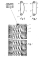
- Figure 1 shows an outline of principle of a bobbin 1 comprising a core of a helical spring 2.
- a grating 3 of a lacing wire is mounted on the helical spring 2.
- the grating 3 is manufactured by the lacing wire being bent into a tubular flat spiral band of a length sufficient for a coating of the total curved surface of the helical spring, and whereby the individual windings of the spiral band are of a width fitting to the desired resulting winding distance on the helical spring 2, said width tapering off towards the ends of the spiral band.
- the bending may for instance be carried out by means of a bending tool including a turnable mandrel.
- the mandrel is provided with two optionally turnable pins projecting axially outwards from one end surface of said mandrel.
- One of these pins is cylindrical, coaxial to the mandrel, and furthermore of a diameter corresponding to twice the inner ra- djus of curvature of the rounded corners and ends of the completed spiral band.
- the other pin is preferably of a greater diameter and optionally radially displaceable relative to the mandrel.
- the space between the surfaces of the pins is adjustable relative to the thickness of the lacing wire used in such a manner that said wire without difficulties is displaceable through said space.
- the bending is carried out by advancing the lacing wire stepwise in the space between the two pins under an angle with the axis of the mandrel determined by the rise desired from winding to winding in the spiral band, whereafter bendings are carried out according to predetermined advancing lengths by turning the mandrel a predetermined angle in such a manner that the lacing wire advanced through the space is bent said angular length between the two pins.
- the spiral band is produced through a successive advancing and bending of the lacing wire.
- the individual steps and the combination thereof are electronically controllable, e.g. by numeric control.
- the spiral band is mounted on the helical spring 2 by being pulled on-the windings of the helical spring and by the ends of the lacing being fastened as illustrated in details in Figure 1.
- Figures 2 and 3 illustrate examples of the profile of the individual windings in the lacing wire with convex outer sides. These outer sides can either be trapezoidal, cf. Figure 2, with the short parallel side 4 of the trapezium facing outwards on the bobbin 1 or be shaped as a segment of a circle, cf. Figure 3, with the curved side 4 facing outwards on the bobbin, whereas the innermost winding lengths 5 are planar, It appears immediately that when the helical spring is in the stretched out position shown in Figures 2 and 3, said spring forces the grating 3 into an outer position on the bobbin 1 with the planar inner winding lengths 5 tightly abutting the helical spring 2.
- the grating 3 may be pressed inwards on the bobbin 1 until the outer convex sides 4 of the grating 3 abut the windings 2', 2" of the helical spring, whereby the bobbin 1 takes up its minimum diameter.
- the helical spring 2 moves again into the position of Figures 2 and 3 and forces the grating 3 outwards into the outer position again, provided said grating is not retained in another manner.
- FIGS 4 to 7 illustrate another embodiment of a bobbin 11 according to the invention.
- This bobbin comprises likewise a helical spring 12, the end windings of which abut two end parts 14, 14'.
- the bobbin 11 is maintained biased by means of two sets of outer lamellas 13, 13' guided and retained by two end rings 15, 15' and a central ring 16.
- the end rings are secured on the end parts 14, 14' by means of clamps 18 of any known art.
- the lamellas 13, 13' of the two sets are mutually displaced in the peripheral direction of the bobbin 11.
- Each lamella comprises a longitudinal trapezoidal recess, the short parallel side of which faces outwards from the bobbin and through which the end ring 15, 15' and the central ring 16 are also extending.
- the end rings 15, 15' are secured on the end parts 14, 14' coaxially with the helical spring 12, whereas the central ring 16 is loosely situated in the recesses of the two sets of lamellas 13, l3'.
- the lamellas 13, 13' are guided laterally in gates 17 in a bottom plate in the end parts 14, 14' and they are movable both in axial and in radial direction in said gates.
- the helical spring 12 keeps the end parts 14, 14' and consequently the end rings 15, l5' and the lamellas 13, 13' stretched out in the position shown in Figure 4 in such a manner that the sets of lamellas 13, 13' are pressed outwards into an outer position with the greatest possible outer diameter for the bobbin 11.
- the lamellas 13, 13' can enter the position of Figure 5 as a consequence of a radial pressure from the outside and furthermore a corresponding inwardly displaced position at the central ring 16 in such a manner that the outer diameter of the bobbin is reduced.
- the extent of the diameter reduction is determined by the width of the recesses in the lamellas 13 and by the diameter of the end rings 15, 15' and the central ring 16.
- the inward displacement of the lamellas 13, 13' at the axial compression of the bobbin 11 can be further ensured by means of an inclined bevelling of the outer annular rim 19 of the end parts, the underside of said rim thereby assisting in pressing the lamella inwards at the axial compression of the bobbin.
- the end parts 14, 14' can be completely.or partially pulled into shape from a metal plate in which the gates 17 and the holes for the clamps 18 are punched out, or the end parts may be cast in one piece.
- the lamellas 13, 13' may be made of sheet material or be bent into the desired shape of metal wire or be cast.
- the material used for the bobbins is preferably stainless steel and stainless spring steel for the helical spring, but the lamellas and the end parts may for instance also be made of plastics.
Landscapes
- Engineering & Computer Science (AREA)
- Textile Engineering (AREA)
- Storage Of Web-Like Or Filamentary Materials (AREA)
- Springs (AREA)
Applications Claiming Priority (2)
| Application Number | Priority Date | Filing Date | Title |
|---|---|---|---|
| DK4161/83 | 1983-09-13 | ||
| DK416183A DK416183A (da) | 1983-09-13 | 1983-09-13 | Hylster til understoetning af tekstilstrenge, der skal varme- og/eller vaadbehandles |
Publications (1)
| Publication Number | Publication Date |
|---|---|
| EP0139191A1 true EP0139191A1 (de) | 1985-05-02 |
Family
ID=8130848
Family Applications (1)
| Application Number | Title | Priority Date | Filing Date |
|---|---|---|---|
| EP84110519A Ceased EP0139191A1 (de) | 1983-09-13 | 1984-09-04 | Textilspule für die Behandlung mit Flüssigkeiten und/oder Wärme |
Country Status (6)
| Country | Link |
|---|---|
| US (1) | US4603562A (de) |
| EP (1) | EP0139191A1 (de) |
| BR (1) | BR8404553A (de) |
| DK (1) | DK416183A (de) |
| ES (1) | ES535873A0 (de) |
| FI (1) | FI843519L (de) |
Families Citing this family (1)
| Publication number | Priority date | Publication date | Assignee | Title |
|---|---|---|---|---|
| KR100865456B1 (ko) | 2007-07-19 | 2008-10-28 | 이동현 | 코일 형태의 지지 수단을 갖는 염색용 보빈 |
Citations (5)
| Publication number | Priority date | Publication date | Assignee | Title |
|---|---|---|---|---|
| DE919765C (de) * | 1950-10-05 | 1954-11-04 | Joseph Annicq | Spule oder Traeger fuer das Nassbehandeln von Textilgut in Wickelform |
| US2818222A (en) * | 1953-12-08 | 1957-12-31 | Scholl Werner | Axially compressible reel for filamentary coils |
| DE1460211A1 (de) * | 1964-08-31 | 1968-11-14 | Heinrich Buddecke | Garnspule |
| CH521282A (de) * | 1970-08-13 | 1972-04-15 | Scholl Ag | Spulenhülse |
| GB1363363A (en) * | 1972-02-25 | 1974-08-14 | Fmk Mfg Ltd | Dye spring centres |
Family Cites Families (4)
| Publication number | Priority date | Publication date | Assignee | Title |
|---|---|---|---|---|
| GB694815A (en) * | 1950-10-05 | 1953-07-29 | Joseph Annicq | Porous resilient bobbin |
| US2614764A (en) * | 1950-10-05 | 1952-10-21 | Annicq Joseph | Porous resilient bobbin |
| DE926066C (de) * | 1952-09-13 | 1955-04-04 | Max Edmund Korff | Radial nachgiebige Spule oder Traeger fuer die Behandlung von Fasergut in Wickelform |
| GB1137609A (en) * | 1967-05-19 | 1968-12-27 | K Dye Springs Ltd | Dye spring centres |
-
1983
- 1983-09-13 DK DK416183A patent/DK416183A/da not_active Application Discontinuation
-
1984
- 1984-08-29 US US06/645,284 patent/US4603562A/en not_active Expired - Fee Related
- 1984-09-04 EP EP84110519A patent/EP0139191A1/de not_active Ceased
- 1984-09-07 FI FI843519A patent/FI843519L/fi not_active Application Discontinuation
- 1984-09-12 BR BR8404553A patent/BR8404553A/pt unknown
- 1984-09-13 ES ES535873A patent/ES535873A0/es active Granted
Patent Citations (5)
| Publication number | Priority date | Publication date | Assignee | Title |
|---|---|---|---|---|
| DE919765C (de) * | 1950-10-05 | 1954-11-04 | Joseph Annicq | Spule oder Traeger fuer das Nassbehandeln von Textilgut in Wickelform |
| US2818222A (en) * | 1953-12-08 | 1957-12-31 | Scholl Werner | Axially compressible reel for filamentary coils |
| DE1460211A1 (de) * | 1964-08-31 | 1968-11-14 | Heinrich Buddecke | Garnspule |
| CH521282A (de) * | 1970-08-13 | 1972-04-15 | Scholl Ag | Spulenhülse |
| GB1363363A (en) * | 1972-02-25 | 1974-08-14 | Fmk Mfg Ltd | Dye spring centres |
Also Published As
| Publication number | Publication date |
|---|---|
| ES8506830A1 (es) | 1985-08-16 |
| ES535873A0 (es) | 1985-08-16 |
| DK416183D0 (da) | 1983-09-13 |
| FI843519A0 (fi) | 1984-09-07 |
| US4603562A (en) | 1986-08-05 |
| FI843519L (fi) | 1985-03-14 |
| BR8404553A (pt) | 1985-08-06 |
| DK416183A (da) | 1985-03-14 |
Similar Documents
| Publication | Publication Date | Title |
|---|---|---|
| US2365980A (en) | Mandrel | |
| US4270710A (en) | Resiliently compressible bobbin | |
| KR101802237B1 (ko) | 원사 염색용 보빈 | |
| US2277602A (en) | Method of making an endless wound clutch facing | |
| US2285263A (en) | Forming tool | |
| CN107405575B (zh) | 用于制造线束的装置和方法 | |
| JPS6344875B2 (de) | ||
| US3753534A (en) | Resiliently compressible bobbin made of plastic material | |
| US4659032A (en) | Spools for yarns, threads or the like | |
| US4603562A (en) | Bobbin supporting textile strands to be subjected to a heat and/or wet treatment | |
| EP0348721A1 (de) | Axial verformbare Hülse | |
| US4477034A (en) | Thread catching structure | |
| US4946114A (en) | Method and dye tube for uniform compression of yarn | |
| US9975298B2 (en) | Filament winding apparatus | |
| US3870242A (en) | Yarn retarding device | |
| US3344592A (en) | Wire tensioning device | |
| US3561696A (en) | Sleeve for treatment of textile threads and yarns | |
| US4433815A (en) | Tube which can be axially stacked | |
| US4402474A (en) | Cylindrical coil carrier for receiving threads and yarns | |
| US3896860A (en) | Assembly for preforming wire during helical winding | |
| US4777860A (en) | Braiding nose | |
| AU2005203629A1 (en) | Winding Device for Removing Cut Binding Material | |
| US3031004A (en) | Method of producing self locking wire inserts | |
| US2614764A (en) | Porous resilient bobbin | |
| EP0433918B1 (de) | Verfahren und Apparat zur Herstellung eines Wulstringes für Luftreifen |
Legal Events
| Date | Code | Title | Description |
|---|---|---|---|
| PUAI | Public reference made under article 153(3) epc to a published international application that has entered the european phase |
Free format text: ORIGINAL CODE: 0009012 |
|
| AK | Designated contracting states |
Designated state(s): AT BE CH DE FR GB IT LI LU NL SE |
|
| 17P | Request for examination filed |
Effective date: 19851024 |
|
| 17Q | First examination report despatched |
Effective date: 19870128 |
|
| STAA | Information on the status of an ep patent application or granted ep patent |
Free format text: STATUS: THE APPLICATION HAS BEEN REFUSED |
|
| 18R | Application refused |
Effective date: 19871001 |
|
| RIN1 | Information on inventor provided before grant (corrected) |
Inventor name: MEYER, HANS Inventor name: HARTMANN, VIGGO EMIL |