EP0138831B1 - Rotary electrode disk apparatus for producing metal powders - Google Patents
Rotary electrode disk apparatus for producing metal powders Download PDFInfo
- Publication number
- EP0138831B1 EP0138831B1 EP84900673A EP84900673A EP0138831B1 EP 0138831 B1 EP0138831 B1 EP 0138831B1 EP 84900673 A EP84900673 A EP 84900673A EP 84900673 A EP84900673 A EP 84900673A EP 0138831 B1 EP0138831 B1 EP 0138831B1
- Authority
- EP
- European Patent Office
- Prior art keywords
- electrode
- disc
- diameter
- chamber
- speed
- Prior art date
- Legal status (The legal status is an assumption and is not a legal conclusion. Google has not performed a legal analysis and makes no representation as to the accuracy of the status listed.)
- Expired - Lifetime
Links
Images


Classifications
-
- B—PERFORMING OPERATIONS; TRANSPORTING
- B22—CASTING; POWDER METALLURGY
- B22F—WORKING METALLIC POWDER; MANUFACTURE OF ARTICLES FROM METALLIC POWDER; MAKING METALLIC POWDER; APPARATUS OR DEVICES SPECIALLY ADAPTED FOR METALLIC POWDER
- B22F9/00—Making metallic powder or suspensions thereof
- B22F9/02—Making metallic powder or suspensions thereof using physical processes
- B22F9/14—Making metallic powder or suspensions thereof using physical processes using electric discharge
-
- B—PERFORMING OPERATIONS; TRANSPORTING
- B23—MACHINE TOOLS; METAL-WORKING NOT OTHERWISE PROVIDED FOR
- B23K—SOLDERING OR UNSOLDERING; WELDING; CLADDING OR PLATING BY SOLDERING OR WELDING; CUTTING BY APPLYING HEAT LOCALLY, e.g. FLAME CUTTING; WORKING BY LASER BEAM
- B23K10/00—Welding or cutting by means of a plasma
-
- H—ELECTRICITY
- H05—ELECTRIC TECHNIQUES NOT OTHERWISE PROVIDED FOR
- H05H—PLASMA TECHNIQUE; PRODUCTION OF ACCELERATED ELECTRICALLY-CHARGED PARTICLES OR OF NEUTRONS; PRODUCTION OR ACCELERATION OF NEUTRAL MOLECULAR OR ATOMIC BEAMS
- H05H1/00—Generating plasma; Handling plasma
- H05H1/24—Generating plasma
- H05H1/26—Plasma torches
- H05H1/32—Plasma torches using an arc
- H05H1/34—Details, e.g. electrodes, nozzles
- H05H1/3421—Transferred arc or pilot arc mode
-
- B—PERFORMING OPERATIONS; TRANSPORTING
- B22—CASTING; POWDER METALLURGY
- B22F—WORKING METALLIC POWDER; MANUFACTURE OF ARTICLES FROM METALLIC POWDER; MAKING METALLIC POWDER; APPARATUS OR DEVICES SPECIALLY ADAPTED FOR METALLIC POWDER
- B22F9/00—Making metallic powder or suspensions thereof
- B22F9/02—Making metallic powder or suspensions thereof using physical processes
- B22F9/06—Making metallic powder or suspensions thereof using physical processes starting from liquid material
- B22F9/08—Making metallic powder or suspensions thereof using physical processes starting from liquid material by casting, e.g. through sieves or in water, by atomising or spraying
- B22F9/082—Making metallic powder or suspensions thereof using physical processes starting from liquid material by casting, e.g. through sieves or in water, by atomising or spraying atomising using a fluid
- B22F2009/084—Making metallic powder or suspensions thereof using physical processes starting from liquid material by casting, e.g. through sieves or in water, by atomising or spraying atomising using a fluid combination of methods
-
- H—ELECTRICITY
- H05—ELECTRIC TECHNIQUES NOT OTHERWISE PROVIDED FOR
- H05H—PLASMA TECHNIQUE; PRODUCTION OF ACCELERATED ELECTRICALLY-CHARGED PARTICLES OR OF NEUTRONS; PRODUCTION OR ACCELERATION OF NEUTRAL MOLECULAR OR ATOMIC BEAMS
- H05H1/00—Generating plasma; Handling plasma
- H05H1/24—Generating plasma
- H05H1/26—Plasma torches
- H05H1/32—Plasma torches using an arc
- H05H1/34—Details, e.g. electrodes, nozzles
- H05H1/3436—Hollow cathodes with internal coolant flow
Definitions
- the invention relates to a rotary disc electrode apparatus for producing powder from solid stock, and more particularly to such apparatus capable of producing generally spherical, high-purity metallic powder in commercial quantities.
- Metallic and other powders are in wide use in the metalworking industry in forming and shaping processes and in forming composite materials by sintering a mixture of powders. Often these applications require powders which are preferably spherical and of small, uniform size, e.g. 50-500 microns. Conventionally, powders were made by chemical reduction of metallic salts, comminution of solid stock, gas jet disruption of a stream of liquid metal (gas atomisation) and water jet disruption of a stream of liquid metal (water atomisation), and by other mechanical means. For certain critical applications, these techniques rendered poor results in terms of purity, size, shape and uniformity. A more satisfactory technique isthe rotating electrode process taught in U.S. Patents 3,099,041 and 3,802,816.
- an atmospherically controlled chamber within which is included a stationary electrode and an elongate, rotatable rod of material to be processed which acts as the second electrode.
- a motor rotates the rod as it is longitudinally advanced toward the first electrode.
- An arc struck between the electrodes consumes the rod material and rotation of the rod casts the melted material off by centrifugal force so that it forms a powder.
- the bar is consumed until only an unusable stub remains, whereupon a new bar may be inserted.
- US-A-4036568 discloses an apparatus for the manufacture of powders which employs a rotating consumable electrode which is in the form of a rod with the surface of the consumable electrode being placed near to the surface of the counter electrode from which an arc is struck.
- the invention results from the realization that an improved, highly efficient apparatus for rotary electrode processing of larger diameter, higher purity, commercially available stock into powder can be effected using a rotatable disc-shaped consumable electrode of the stock and moving the arc between the electrodes inwardly on the rotating disc as it is consumed, while proportionately increasing the speed of rotation to maintain a constant peripheral speed of the edge of the diminishing disc.
- the present invention provides a rotary disc electrode apparatus for producing metal powders, which comprises:
- the means for moving the arc inwardly on the disc electrode may include means for varying the angle of the first electrode relative to the consumable disc electrode.
- the second means for mounting may include a rotatable mandrel and means for attaching a consumable disc electrode to the mandrel.
- the means for rotating may include a motor and in such embodiments the means for varying the speed of rotation preferably includes means responsive to said monitoring means for controlling speed of the motor.
- the invention is accomplished with a rotary electrode apparatus having a chamber in which the rotating disc electrode is mounted.
- a controlled atmosphere for encouraging and sustaining the arc burning process is maintained in the chamber.
- the interior of the chamber is vacuum evacuated and backfilled with an inert gas, such as helium, to a desired pressure.
- the inside surface of the chamber of typically stainless steel and double-wall construction is provided to enable water cooling of the chamber.
- a Pyrex or quartz window is provided to permit viewing of the process.
- a first electrode (cathode) is mounted in the chamber to confront the circumferential edge of the disc electrode (anode).
- the first electrode may be composed of tungsten or thoriated tungsten or other electron emissive metal. It will typically be housed within a copper nozzle having a port proximate the distal end of the first electrode through which the arc is emitted. Means are provided for striking an arc between the first electrode and a circumferential portion of the disc electrode.
- the latter is composed of solid metal stock such as Ti 6AI 4V, stainless steel, nickel base superalloy or other metal alloy. High purity remelt ingots of nickel base superalloys are typically produced in diameters of from 20.3 to 63.5 cm (8 to 25 inches).
- Electrode discs may be readily produced from such high quality ingots. Much less effort is involved than is required to reduce such superalloy ingots to the small diameter typically 6.35 cm (2 1/2 inches) rods used in the prior art rotary electrode apparatus. The arc effects burning or melting of the metal stock.
- the disc electrode is preferably mounted on a mandrel which is rotated by a motor external to the chamber.
- the mandrel may itself be composed of solid stock connected to the end of a shaft driven by the motor.
- a variable- speed D.C. motor having a large pulley driving a flat belt is utilized.
- the belt in turn drives a smaller crowned pulley of the rotor shaft.
- Pulley diameter ratio may be approximately 7:1 so that high rotational speeds (e.g. up to approximately 18,000 RPM) are obtained for rotating the disc electrode.
- the motor rotates the disc electrode at sufficient speed so that the melted circumferential portions are spun off of the electrode.
- a constant peripheral or circumferential speed is required as the diameter of the disc diminishes in order to maintain a constant centrifugal force upon melted portions being spun from the disc. In this way spheres of uniform size and quality are produced. Accordingly, means may be provided for varying the speed of rotation of the disc inversely with respect to the diameter thereof.
- a feedback and control system is provided which includes a disc diameter monitor such as a monotonic photoelectric device for measuring the diameter of the disc.
- a speed control responds to such measurements to increase the speed of disc rotation, typically by increasing the speed of the motor, as the disc diameter diminishes.
- a preferred tangential velocity is 4990 cm/sec (163.62 ft/sec) that is the speed typically maintained by rotating the 6.35 cm (2 1/2 inch) diameter by 152.5 cm (60 inch) long solid stock rod of the prior art at a constant rate of 15,000 RPM.
- the speed control increases the rate of disc rotation as the disc diameter decreases, as shown in the following table:
- Means are also typically provided for moving the arc inwardly on the rotating disc electrode as successive circumferences thereof are consumed.
- a feedback and control system may be used for such purpose.
- the disc diameter monitor provides measurements to control devices such as translational and/or angular servomechanisms which are programmed to respond to diameter measurements and adjust the portion of the first electrode in such a manner as to move the arc inwardly on the disc electrode as that electrode is consumed.
- control devices such as translational and/or angular servomechanisms which are programmed to respond to diameter measurements and adjust the portion of the first electrode in such a manner as to move the arc inwardly on the disc electrode as that electrode is consumed.
- manual controls are provided for varying the position of the first electrode, either translationally or angularly, relative to the consumable disc electrode.
- FIG. 1 a rotary electrode apparatus 10 according to this invention.
- a manifold 12 communicates with the interior of a chamber 14 so that a controlled atmosphere may be provided therein.
- a door 16 is hingeably mounted by hinge 18 at an open end of the chamber. Door 16 is closed during operation of apparatus 10 and may be opened between operations to gain access to the interior of the chamber for cleaning, inspection and recharging with essential materials.
- Afunnel 20 in the bottom of chamber 12 converges into a receptacle 22, which collects powder produced in chamber 14 and transfers such powder to desired storage or use locations.
- chamber 14 As shown in Figure 2, the interior of chamber 14 is provided with a controlled atmosphere via manifold 12. Initially the chamber is vacuum evacuated, as indicated by arrow 24, by an unpictured external vacuum pump. Inert gas such as helium is then injected, as indicated by arrow 26, such that a low positive pressure is provided. A valve 28 regulates helium flow into chamber 14, thereby enabling maintenance of chamber pressure within a desired range, e.g. 104.75 to 135.8 kPa (5-5 psig).
- a desired range e.g. 104.75 to 135.8 kPa (5-5 psig).
- Electrode 30 surrounded by a nozzle 31 has an obscured port proximate the tip of the electrode 30.
- This assembly comprising a D.C. transferred arc plasma torch is adjustably attached, as is shown more clearly in Figure 4, to a mounting bracket 32, which is in turn mounted to the inside of door 16.
- Electrode 30 can be adjusted up and down along bracket 32 and angularly as indicated by double headed arrow 34. Such adjustment will be described more fully in connection with Figure 4.
- a mandrel 42 comprising a narrow (approximately 6.35 cm (2 1/2 inch) diameter) rod of solid stock fixed to the end of an external shaft 43 mounted in bearing support 41, which is in turn rotatably driven through pulleys 43a, 43b and belt 43c by shaft 43d of motor 44 mounted on a base 45.
- a seal 46 prevents leakage of the controlled inert atmosphere through the gap between mandrel 42 and wall 40, as known in the prior art.
- a disc electrode 48 mounted proximate the end of mandrel 42 and inside chamber 14 is a disc electrode 48 composed of consumable solid metal stock.
- Electrode 30 is then adjusted translationally and/or angularly downwardly so that arc 50 moves inwardly on disc 48 to enable consumption of successive circumferential edges thereof.
- the speed of rotation is sufficient to spin off such melted portions from electrode 48 as indicated by particles 54. These particles cool to form metallic spherical powder which drops to the bottom of chamber 14 through funnel 20 and into the receptacle 22, Figure 1.
- a disc diameter monitor 60 senses a reduced disc diameter and relays such information to a speed control 62 which increases the speed of rotation of disc electrode 48 so that melted portion particles 54 are cast off with a uniform centrifugal force.
- Electrode 48 is provided with an axial hole 64 and is abutted against the inner end of mandrel 42 such that axial hole 64 registers with countersunk hole 66 which extends into mandrel 42 and provides a sliding fit of .005 to .010 cm (0.002-0.004 inch) clearance.
- a bushing 68 having an axial hole 70 is fitted through axial disc hole 64 and into enlarged portion 72 of mandrel bore 66.
- a capscrew 74 is inserted through hole 70 and is caused to threadably engage the threaded (1/2-13 UNC) wall of reduced diameter portion 76 of mandrel bore 66. Head 77 of screw 74 restricts removal of bushing 68, and head 78 of bushing 68 retains disc 48.
- New discs 48 are placed against the face of a 6.35 cm (2 1/2 inches) mandrel 42. They are correctly located by the disc centering plug 78 and held down by a 1/2-13 UNC socket head cap screw 77 or similar screw acting on the thread tapped into the mandrel.
- Disc centering plug 78 is a sliding fit of .005 to .010 cm (0.002-0.004 inch clearance) in the mandrel: clearance 66 ensures that the disc is always clamped tight.
- electrode 30 is adjustable so that the arc may be moved radially inwardly on electrode 48 as successive circumferential portions thereof are consumed. Electrode 30 extends from arc mechanism 80 and is surrounded by nozzle 31, having port 82 at the end thereof. Both electrode and nozzle are retractable within the arc mechanism, which is in turn mounted to arm 84 of an angle bracket 86. A thumb screw 88 is fitted through a hole 90 in arm 92 and is screwed into threaded hole 94 of mounting piece 96. A similar thumb screw 98 is fitted through a slot 100 in mounting bracket 32 and into an obscured threaded hole at the opposite end of piece 96. Bracket 32 is in turn mounted to the inside of chamber door 16 by bolts 97.
- electrode 30 By loosening screw 98, and moving the screw longitudinally in slot 100, electrode 30 can be adjusted to any point along the length of bracket 32. Its position is then fixed by tightening screw 98. Likewise, the angular disposition of electrode 30 may be altered by loosening screw 88, rotating the electrode 30 up or down, and then retightening the screw 88 to fix the electrode 30 in a desired position.
- Such translational and/or rotational adjustment of electrode 30 occurs as disc electrode 48 is consumed by arc 50.
- arc 50 from electrode (cathode) 30 consumes the circumferential portion of disc electrode (anode) 48.
- the disc diameter is thus reduced as indicated by reduced diameter circumferential portion 102.
- Arc 50 is moved inwardly on disc 48 so that portion 102 may be melted.
- Such movement may be performed by loosening screw 98 and lowering electrode mechanism 80 to a position on bracket 32 indicated generally by arrow 104 such that electrode 30 maintains perpendicular confrontation with disc circumferential portion 102.
- screw 88 may be loosened and electrode 30 rotated downwardly in the direction of arrow 34 so that arc 50 impinges upon circumferential edge 102.
- Figure 4 further discloses electrode wiring 106 entering mechanism 88 and water and helium lines 108, 110, the function of which will be described with Figure 8.
- Arc mechanism 80 is again fixed to one arm 111 of an angle bracket 112. Through an obscured hole in the other bracket arm 113 extends a threaded shaft 114 of a rotational servomechanism 116. Nuts 118, 120 are fitted onto shaft 114 on either side of bracket arm 113 and are tightened about the arm to enable arc mechanism 80 and electrode 30 to rotate with shaft 114..
- Servomechanism 116 is in turn mounted to rack 122 by means of a screw 124 extending through a hole 126 in rack 122 and threadably secured to an obscured hole in rotational servo 116.
- Rack 122 is fitted for longitudinal travel within a slotted recep- etacte 128.
- a translational servomechanism 130 includes a shaft 132 which extends through the axial hole 134 of a pinion 136 which in turn meshes with rack 122. Counterclockwise rotation of shaft 132 causes downward movement of rack 122 and thus similar downward movement of electrode 30 carried thereby. Clockwise rotation of servoshaft 132 results in upward movement of the electrode 30. Thus the arc 50 may be moved automatically inwardly on disc 48 in a translational manner.
- servomechanisms 116, 130 respond to the measurements provided by disc diameter monitor 60.
- Monitor 60 indicates a progressively reduced diameter disc and servomechanisms 116, 130 connected to monitor 60 via line 140 respond to adjust the position of electrode 30 rotationally, arrow 34, and/or translationally, arrow 146, so as to move arc 50 inwardly as shown by arrow 148 on decreasing diameter electrode 48.
- Monitor 60 is likewise connected to speed control 62 via line 150. Diameter measurements are thus also provided to speed control 62 which is programmed to vary the speed at which motor 44 rotates disc electrode 48 inversely with the diameter of the disc 48, i.e., as the disc diameter is reduced the rotational speed is increased. In this manner a constant circumferential or tangential velocity is maintained for all diameters of disc electrode 48. Constant centrifugal force and thus metal spheres of uniform size and quality are consequently provided.
- a preferred disc monitor 60 includes a monotonic photoelectric device comprising a radiation source 160 and sensor 162 disposed on opposite sides of disc 48.
- a radiation source 160 and sensor 162 disposed on opposite sides of disc 48.
- the signal sent through line 150 to the speed control 62 and similarly to the unpictured servomechanisms reflects this and these control mechanisms respond to adjust the devices they control; i.e., speed control 62 increases the rotational speed of disc electrode 48 and the servomechanisms adjust the cathode electrode to move the arc inwardly on the disc electrode.
- Nozzle 31 includes channels 170 through which cooling water from line 108, Figure 4, is circulated as indicated by arrows 172.
- Electrode 30 includes similar channels 174 through which cooling water, arrows 176, is passed.
- Helium from line 110, Figure 4 is provided as shown by arrows 180, Figure 8, through the space 182 between nozzle 31 and electrode 30.
- tungsten electrode (cathode) 30 and copper nozzle 31 are positioned, as indicated by the phantom figure, proximate disc electrode 48.
- An ignition arc circuit 184 including a powder supply 186 is completed by closing switch 188 and a non-transfer ignition arc 190 is thereby struck between electrode 30 and nozzle 31.
- a transferred arc 50 is struck between electrode 30 and disc electrode 48.
- Switch 188 is immediately opened and electrode 30 and nozzle 31 retract, as shown by arrow 192, two to three inches from disc electrode 48.
- the trasnferred arc 50 generated by power supply 194 continues to burn. Note that switch 196 in the transferred arc circuit 198 remains closed. Consumption of the disc electrode 48 proceeds in the manner previously described. When melting of the subject disc is completed, switch 96 is opened and the arc 50 is turned off.
- FIG. 9 disc 48 is mounted to mandrel 42a, which is driven by a precision spindle 41 rather than a bearing support and motor.
- Capscrew 77 fastens bushing 68 and disc 48 to mandrel 42, which passes through seal bearing 46.
- the preferred manual control mechanism for a plasma gun 29a, Figure 10 includes a ball and socket joint and seal 220, including a housing 222 holding spherical socket 224 which receives a ball 226.
- An "O" ring 228 in socket 224 seals against ball 226 and a similar "0" ring 230 in bore 232 of ball 226 seals against plasma gun 29a to allow rotation in the vertical plane, arrows 234, and translation, arrows 236, of plasma gun 29a.
Abstract
Description
- The invention relates to a rotary disc electrode apparatus for producing powder from solid stock, and more particularly to such apparatus capable of producing generally spherical, high-purity metallic powder in commercial quantities.
- Metallic and other powders are in wide use in the metalworking industry in forming and shaping processes and in forming composite materials by sintering a mixture of powders. Often these applications require powders which are preferably spherical and of small, uniform size, e.g. 50-500 microns. Conventionally, powders were made by chemical reduction of metallic salts, comminution of solid stock, gas jet disruption of a stream of liquid metal (gas atomisation) and water jet disruption of a stream of liquid metal (water atomisation), and by other mechanical means. For certain critical applications, these techniques rendered poor results in terms of purity, size, shape and uniformity. A more satisfactory technique isthe rotating electrode process taught in U.S. Patents 3,099,041 and 3,802,816. Typically in this process an atmospherically controlled chamber is provided within which is included a stationary electrode and an elongate, rotatable rod of material to be processed which acts as the second electrode. A motor rotates the rod as it is longitudinally advanced toward the first electrode. An arc struck between the electrodes consumes the rod material and rotation of the rod casts the melted material off by centrifugal force so that it forms a powder. The bar is consumed until only an unusable stub remains, whereupon a new bar may be inserted.
- US-A-4036568 discloses an apparatus for the manufacture of powders which employs a rotating consumable electrode which is in the form of a rod with the surface of the consumable electrode being placed near to the surface of the counter electrode from which an arc is struck.
- One problem that is associated with the previously described device is the tendency of the free end of the bar or consumable electrode to wobble as a result of the centrifugal force acting on it due to its own rotation. Furthermore, the bars are typically 152.5 cm (sixty inches) long and leave a 25.4 cm (ten-inch stub) which effects an efficiency of only eighty-three and a third percent. A higher conversion rate is clearly desirable.
- These bars are available in reasonably pure form in generally 5 to 7.5 cm (two to three inch) diameters. However, recently the demand has been for even higher purity of the powders. Unfortunately, higher purity bar stock is not readily available in the 5 to 7.5 cm (two to three inch) diameter size but in much larger sizes, e.g. 20.3 to 63.5 cm (eight to twenty-five inch) diameters, which are difficult to handle and process.
- It is therefore an object of this invention to provide an improved apparatus for the rotary electrode process of powder production.
- It is a further object of this invention to provide such apparatus which can provide higher purity powder from commercially available stock.
- It is a further object of this invention to provide such apparatus which eliminates the problems associated with the centrifugal forces applied to the free end of conventional bar stock.
- It is a further object of this invention to provide such apparatus which provides mbre efficient production of powder from solid stock.
- It is a further object of this invention to provide such apparatus which can be used in conventional rotary electrode process machines with minimal alteration.
- It is a further object of this invention to provide such apparatus which produces higher purity, generally spherical powder from commercially available high purity stock.
- It is a further object of this invention to provide such apparatus which reduces the need for extensive preparation and handling of solid stock prior to processing.
- The invention results from the realization that an improved, highly efficient apparatus for rotary electrode processing of larger diameter, higher purity, commercially available stock into powder can be effected using a rotatable disc-shaped consumable electrode of the stock and moving the arc between the electrodes inwardly on the rotating disc as it is consumed, while proportionately increasing the speed of rotation to maintain a constant peripheral speed of the edge of the diminishing disc.
- Accordingly, the present invention provides a rotary disc electrode apparatus for producing metal powders, which comprises:
- a chamber for maintaining a controlled atmosphere therein;
- first means for mounting a first electrode in said chamber;
- a rotatable shaft mounted outside said chamber;
- second means in said chamber attachable to said shaft for securing a second electrode in said chamber proximate said first electrode;
- means for striking an electric arc between said first electrode and said second electrode; and
- means for rotating said second electrode at sufficient speed to enable casting off of-melted circumferential portions therefrom;
- wherein the second electrode is in the form of a consumable disc having a larger diameter than said means for securing, the apparatus includes means for monitoring the diameter of the disc electrode, the means for rotating includes means for varying the speed of rotation of said disc electrode inversely with respect to the diameter thereof and said first means for mounting includes means for moving said arc inwardly on said disc electrode towards said means for securing as successive circumferential portions of said disc electrode are consumed and the diameter of the disc decreases.
- The means for moving the arc inwardly on the disc electrode may include means for varying the angle of the first electrode relative to the consumable disc electrode.
- The second means for mounting may include a rotatable mandrel and means for attaching a consumable disc electrode to the mandrel. The means for rotating may include a motor and in such embodiments the means for varying the speed of rotation preferably includes means responsive to said monitoring means for controlling speed of the motor.
- Other objects, features and advantages will occur from the following description of a preferred embodiment and the accompanying drawings, in which:
- Figure 1 is a front view of a chamber for housing the rotary electrode apparatus of this invention and the receptacle for receiving spherical metal powders produced thereby;
- Figure 2 is a side diagrammatic sectional view of the rotary electrode apparatus according to this invention;
- Figure 3 is a cross-sectional view of a disc electrode of this invention mounted to a rotatable mandrel;
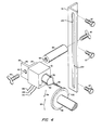
- Figure 4 is an exploded axonometric view of one construction of the means for mounting the first electrode and for moving the arc inwardly on the disc electrode;
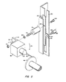
- Figure 5 is an exploded axonometric view of another construction of the means for mounting the first electrode;
- Figure 6 is a schematic diagram view of the means for varying the speed of rotation of said disc electrode and the means for moving the are inwardly on the disc electrode;
- Figure 7 is a schematic side view of a preferred disc diameter monitor utilized by the means for varying the disc rotation speed;
- Figure 8 is a diagrammatic side view, partly in cross-section, of a means for striking an arc used in this invention;
- Figure 9 is a view partially in cross-section of a disc electrode of this invention mounted by an alternative construction to a rotatable mandrel; and
- Figure 10 is a view partially in cross-section of an alternative construction for mounting the first electrode and moving the arc relative to the disc.
- The invention is accomplished with a rotary electrode apparatus having a chamber in which the rotating disc electrode is mounted. A controlled atmosphere for encouraging and sustaining the arc burning process is maintained in the chamber. Typically the interior of the chamber is vacuum evacuated and backfilled with an inert gas, such as helium, to a desired pressure. The inside surface of the chamber of typically stainless steel and double-wall construction is provided to enable water cooling of the chamber. A Pyrex or quartz window is provided to permit viewing of the process.
- A first electrode (cathode) is mounted in the chamber to confront the circumferential edge of the disc electrode (anode). The first electrode may be composed of tungsten or thoriated tungsten or other electron emissive metal. It will typically be housed within a copper nozzle having a port proximate the distal end of the first electrode through which the arc is emitted. Means are provided for striking an arc between the first electrode and a circumferential portion of the disc electrode. The latter is composed of solid metal stock such as Ti 6AI 4V, stainless steel, nickel base superalloy or other metal alloy. High purity remelt ingots of nickel base superalloys are typically produced in diameters of from 20.3 to 63.5 cm (8 to 25 inches). Electrode discs may be readily produced from such high quality ingots. Much less effort is involved than is required to reduce such superalloy ingots to the small diameter typically 6.35 cm (2 1/2 inches) rods used in the prior art rotary electrode apparatus. The arc effects burning or melting of the metal stock.
- The disc electrode is preferably mounted on a mandrel which is rotated by a motor external to the chamber. The mandrel may itself be composed of solid stock connected to the end of a shaft driven by the motor. Typically a variable- speed D.C. motor having a large pulley driving a flat belt is utilized. The belt in turn drives a smaller crowned pulley of the rotor shaft. Pulley diameter ratio may be approximately 7:1 so that high rotational speeds (e.g. up to approximately 18,000 RPM) are obtained for rotating the disc electrode.
- As the disc electrode is rotated successive circumferential portions are melted. The motor rotates the disc electrode at sufficient speed so that the melted circumferential portions are spun off of the electrode.
- A constant peripheral or circumferential speed is required as the diameter of the disc diminishes in order to maintain a constant centrifugal force upon melted portions being spun from the disc. In this way spheres of uniform size and quality are produced. Accordingly, means may be provided for varying the speed of rotation of the disc inversely with respect to the diameter thereof. A feedback and control system is provided which includes a disc diameter monitor such as a monotonic photoelectric device for measuring the diameter of the disc. A speed control responds to such measurements to increase the speed of disc rotation, typically by increasing the speed of the motor, as the disc diameter diminishes.
- A preferred tangential velocity is 4990 cm/sec (163.62 ft/sec) that is the speed typically maintained by rotating the 6.35 cm (2 1/2 inch) diameter by 152.5 cm (60 inch) long solid stock rod of the prior art at a constant rate of 15,000 RPM. To maintain such a surface velocity in the present invention the speed control increases the rate of disc rotation as the disc diameter decreases, as shown in the following table:

- Means are also typically provided for moving the arc inwardly on the rotating disc electrode as successive circumferences thereof are consumed. A feedback and control system may be used for such purpose. Preferably the disc diameter monitor provides measurements to control devices such as translational and/or angular servomechanisms which are programmed to respond to diameter measurements and adjust the portion of the first electrode in such a manner as to move the arc inwardly on the disc electrode as that electrode is consumed. Alternatively, manual controls are provided for varying the position of the first electrode, either translationally or angularly, relative to the consumable disc electrode.
- By utilizing the rotary disc electrode of this invention, conversion efficiency is greatly enhanced. Burning the 6.35 cm (2 1/2 inch) diameter by 152.5 cm (60 inch) long bar utilized by the prior art typically leaves 25.4 cm (10 inch) stub unconsumed, resulting in a conversion rate of 50/ 60 or 83.33%. When a disc (radius r,) according to this invention is burned down to a stub (radius r2) the proportion consumed is given by the ratio

- There is shown in Figure 1 a
rotary electrode apparatus 10 according to this invention. A manifold 12 communicates with the interior of achamber 14 so that a controlled atmosphere may be provided therein. Adoor 16 is hingeably mounted byhinge 18 at an open end of the chamber.Door 16 is closed during operation ofapparatus 10 and may be opened between operations to gain access to the interior of the chamber for cleaning, inspection and recharging with essential materials.Afunnel 20 in the bottom ofchamber 12 converges into areceptacle 22, which collects powder produced inchamber 14 and transfers such powder to desired storage or use locations. - As shown in Figure 2, the interior of
chamber 14 is provided with a controlled atmosphere viamanifold 12. Initially the chamber is vacuum evacuated, as indicated byarrow 24, by an unpictured external vacuum pump. Inert gas such as helium is then injected, as indicated by arrow 26, such that a low positive pressure is provided. Avalve 28 regulates helium flow intochamber 14, thereby enabling maintenance of chamber pressure within a desired range, e.g. 104.75 to 135.8 kPa (5-5 psig). - An
electrode 30, surrounded by anozzle 31 has an obscured port proximate the tip of theelectrode 30. This assembly comprising a D.C. transferred arc plasma torch is adjustably attached, as is shown more clearly in Figure 4, to a mountingbracket 32, which is in turn mounted to the inside ofdoor 16.Electrode 30 can be adjusted up and down alongbracket 32 and angularly as indicated by double headedarrow 34. Such adjustment will be described more fully in connection with Figure 4. - Through indented
central portion 38 ofrear chamber wall 40 extends amandrel 42, comprising a narrow (approximately 6.35 cm (2 1/2 inch) diameter) rod of solid stock fixed to the end of anexternal shaft 43 mounted in bearingsupport 41, which is in turn rotatably driven throughpulleys 43a, 43b andbelt 43c byshaft 43d ofmotor 44 mounted on abase 45. Aseal 46 prevents leakage of the controlled inert atmosphere through the gap betweenmandrel 42 andwall 40, as known in the prior art. Mounted proximate the end ofmandrel 42 and insidechamber 14 is adisc electrode 48 composed of consumable solid metal stock. Anarc 50 is struck, as described hereinafter in Figure 8, betweenelectrode 30 and the circumferential edge ofdisc electrode 48, thereby causing melting of the portion ofelectrode 48 struck by thearc 50.Motor 44 rotatesmandrel 42 and thusdisc electrode 48 as indicated byarrow 52, and the entire circumference of thedisc 48 is consequently melted.Electrode 30 is then adjusted translationally and/or angularly downwardly so thatarc 50 moves inwardly ondisc 48 to enable consumption of successive circumferential edges thereof. The speed of rotation is sufficient to spin off such melted portions fromelectrode 48 as indicated byparticles 54. These particles cool to form metallic spherical powder which drops to the bottom ofchamber 14 throughfunnel 20 and into thereceptacle 22, Figure 1. - As each successive circumferential portion is melted a
disc diameter monitor 60, described in greater detail in Figures 6, 7, senses a reduced disc diameter and relays such information to aspeed control 62 which increases the speed of rotation ofdisc electrode 48 so that meltedportion particles 54 are cast off with a uniform centrifugal force. - The manner of mounting
disc electrode 48 tomandrel 42 is illustrated in Figure 3.Electrode 48 is provided with anaxial hole 64 and is abutted against the inner end ofmandrel 42 such thataxial hole 64 registers with countersunkhole 66 which extends intomandrel 42 and provides a sliding fit of .005 to .010 cm (0.002-0.004 inch) clearance. Abushing 68 having anaxial hole 70 is fitted throughaxial disc hole 64 and into enlarged portion 72 of mandrel bore 66. Acapscrew 74 is inserted throughhole 70 and is caused to threadably engage the threaded (1/2-13 UNC) wall of reduceddiameter portion 76 of mandrel bore 66.Head 77 ofscrew 74 restricts removal ofbushing 68, and head 78 ofbushing 68 retainsdisc 48. -
New discs 48 are placed against the face of a 6.35 cm (2 1/2 inches)mandrel 42. They are correctly located by the disc centering plug 78 and held down by a 1/2-13 UNC sockethead cap screw 77 or similar screw acting on the thread tapped into the mandrel. Disc centering plug 78 is a sliding fit of .005 to .010 cm (0.002-0.004 inch clearance) in the mandrel:clearance 66 ensures that the disc is always clamped tight. - As shown in Figure 4,
electrode 30 is adjustable so that the arc may be moved radially inwardly onelectrode 48 as successive circumferential portions thereof are consumed.Electrode 30 extends fromarc mechanism 80 and is surrounded bynozzle 31, havingport 82 at the end thereof. Both electrode and nozzle are retractable within the arc mechanism, which is in turn mounted to arm 84 of an angle bracket 86. Athumb screw 88 is fitted through ahole 90 inarm 92 and is screwed into threadedhole 94 of mountingpiece 96. Asimilar thumb screw 98 is fitted through aslot 100 in mountingbracket 32 and into an obscured threaded hole at the opposite end ofpiece 96.Bracket 32 is in turn mounted to the inside ofchamber door 16 bybolts 97. By looseningscrew 98, and moving the screw longitudinally inslot 100,electrode 30 can be adjusted to any point along the length ofbracket 32. Its position is then fixed by tighteningscrew 98. Likewise, the angular disposition ofelectrode 30 may be altered by looseningscrew 88, rotating theelectrode 30 up or down, and then retightening thescrew 88 to fix theelectrode 30 in a desired position. - Such translational and/or rotational adjustment of
electrode 30 occurs asdisc electrode 48 is consumed byarc 50. In Figure 4, asdisc 48 is rotated in the direction ofarrow 52,arc 50 from electrode (cathode) 30 consumes the circumferential portion of disc electrode (anode) 48. The disc diameter is thus reduced as indicated by reduced diametercircumferential portion 102.Arc 50 is moved inwardly ondisc 48 so thatportion 102 may be melted. Such movement may be performed by looseningscrew 98 and loweringelectrode mechanism 80 to a position onbracket 32 indicated generally byarrow 104 such thatelectrode 30 maintains perpendicular confrontation with disccircumferential portion 102. Alternatively, screw 88 may be loosened andelectrode 30 rotated downwardly in the direction ofarrow 34 so thatarc 50 impinges uponcircumferential edge 102. - Figure 4 further discloses
electrode wiring 106entering mechanism 88 and water andhelium lines - Automatic adjustment of the
cathode electrode 30 such that the arc moves inwardly on thedisc anode 48 is provided as shown in Figure 5. For clarity, certain details of construction, such as the nozzle, wiring, water and helium lines, are omitted.Arc mechanism 80 is again fixed to one arm 111 of an angle bracket 112. Through an obscured hole in theother bracket arm 113 extends a threaded shaft 114 of arotational servomechanism 116.Nuts bracket arm 113 and are tightened about the arm to enablearc mechanism 80 andelectrode 30 to rotate with shaft 114..Servomechanism 116 is in turn mounted to rack 122 by means of ascrew 124 extending through ahole 126 inrack 122 and threadably secured to an obscured hole inrotational servo 116.Rack 122 is fitted for longitudinal travel within a slotted recep-etacte 128. By rotation of shaft 114servo 116 adjusts the angular disposition ofelectrode 30 in the direction ofarrow 34 so thatarc 50 moves inwardly ondisc 48 as each successive circumferential portion thereof is melted. - Similarly, automatic translational (up and down) movement of
electrode 30, and thusarc 50, is possible. Atranslational servomechanism 130 includes ashaft 132 which extends through theaxial hole 134 of apinion 136 which in turn meshes withrack 122. Counterclockwise rotation ofshaft 132 causes downward movement ofrack 122 and thus similar downward movement ofelectrode 30 carried thereby. Clockwise rotation ofservoshaft 132 results in upward movement of theelectrode 30. Thus thearc 50 may be moved automatically inwardly ondisc 48 in a translational manner. - As shown in Figure 6,
servomechanisms disc diameter monitor 60.Monitor 60 indicates a progressively reduced diameter disc andservomechanisms line 140 respond to adjust the position ofelectrode 30 rotationally,arrow 34, and/or translationally,arrow 146, so as to movearc 50 inwardly as shown byarrow 148 on decreasingdiameter electrode 48. -
Monitor 60 is likewise connected to speedcontrol 62 vialine 150. Diameter measurements are thus also provided to speedcontrol 62 which is programmed to vary the speed at whichmotor 44 rotatesdisc electrode 48 inversely with the diameter of thedisc 48, i.e., as the disc diameter is reduced the rotational speed is increased. In this manner a constant circumferential or tangential velocity is maintained for all diameters ofdisc electrode 48. Constant centrifugal force and thus metal spheres of uniform size and quality are consequently provided. - A
preferred disc monitor 60, Figure 7, includes a monotonic photoelectric device comprising aradiation source 160 andsensor 162 disposed on opposite sides ofdisc 48. As the circumference ofdisc 48 is melted and thus the diameter thereof is reduced for example from 164 to 166, the light fromelement 160 which strikeselement 162 advances. The signal sent throughline 150 to thespeed control 62 and similarly to the unpictured servomechanisms reflects this and these control mechanisms respond to adjust the devices they control; i.e.,speed control 62 increases the rotational speed ofdisc electrode 48 and the servomechanisms adjust the cathode electrode to move the arc inwardly on the disc electrode. - An
arc 50 is struck by aplasma gun 29, as shown in Figure 8.Nozzle 31 includeschannels 170 through which cooling water fromline 108, Figure 4, is circulated as indicated byarrows 172.Electrode 30 includes similar channels 174 through which cooling water,arrows 176, is passed. Helium fromline 110, Figure 4, is provided as shown byarrows 180, Figure 8, through thespace 182 betweennozzle 31 andelectrode 30. - Initially, tungsten electrode (cathode) 30 and
copper nozzle 31 are positioned, as indicated by the phantom figure,proximate disc electrode 48. The details of construction ofnozzle 31 andelectrode 30 in such position are omitted for clarity. Anignition arc circuit 184 including apowder supply 186 is completed by closingswitch 188 and anon-transfer ignition arc 190 is thereby struck betweenelectrode 30 andnozzle 31. Because of the intense ionization of theignition arc 190 and the proximity todisc electrode 48, a transferredarc 50 is struck betweenelectrode 30 anddisc electrode 48.Switch 188 is immediately opened andelectrode 30 andnozzle 31 retract, as shown byarrow 192, two to three inches fromdisc electrode 48. Thetrasnferred arc 50 generated bypower supply 194 continues to burn. Note thatswitch 196 in the transferredarc circuit 198 remains closed. Consumption of thedisc electrode 48 proceeds in the manner previously described. When melting of the subject disc is completed,switch 96 is opened and thearc 50 is turned off. - In a preferred construction, Figure 9,
disc 48 is mounted to mandrel 42a, which is driven by aprecision spindle 41 rather than a bearing support and motor.Capscrew 77 fastensbushing 68 anddisc 48 tomandrel 42, which passes through seal bearing 46. The preferred manual control mechanism for a plasma gun 29a, Figure 10, includes a ball and socket joint and seal 220, including ahousing 222 holdingspherical socket 224 which receives aball 226. An "O"ring 228 insocket 224 seals againstball 226 and a similar "0"ring 230 in bore 232 ofball 226 seals against plasma gun 29a to allow rotation in the vertical plane,arrows 234, and translation,arrows 236, of plasma gun 29a.
Claims (6)
Applications Claiming Priority (2)
| Application Number | Priority Date | Filing Date | Title |
|---|---|---|---|
| US484444 | 1983-04-13 | ||
| US06/484,444 US4488031A (en) | 1983-04-13 | 1983-04-13 | Rotary electrode disc apparatus |
Publications (3)
| Publication Number | Publication Date |
|---|---|
| EP0138831A1 EP0138831A1 (en) | 1985-05-02 |
| EP0138831A4 EP0138831A4 (en) | 1987-02-03 |
| EP0138831B1 true EP0138831B1 (en) | 1990-10-31 |
Family
ID=23924188
Family Applications (1)
| Application Number | Title | Priority Date | Filing Date |
|---|---|---|---|
| EP84900673A Expired - Lifetime EP0138831B1 (en) | 1983-04-13 | 1984-01-09 | Rotary electrode disk apparatus for producing metal powders |
Country Status (6)
| Country | Link |
|---|---|
| US (1) | US4488031A (en) |
| EP (1) | EP0138831B1 (en) |
| JP (2) | JPS60500871A (en) |
| CA (1) | CA1219550A (en) |
| DE (1) | DE3483511D1 (en) |
| WO (1) | WO1984004065A1 (en) |
Cited By (1)
| Publication number | Priority date | Publication date | Assignee | Title |
|---|---|---|---|---|
| TWI616253B (en) * | 2015-04-29 | 2018-03-01 | 財團法人金屬工業研究發展中心 | Electrode unit, electric arc unit, and rotating electrode system |
Families Citing this family (13)
| Publication number | Priority date | Publication date | Assignee | Title |
|---|---|---|---|---|
| US4731515A (en) * | 1986-10-22 | 1988-03-15 | Systems Research Laboratories, Inc. | Method of making powders by electro-discharge machining in a cryogenic dielectric |
| GB2196956A (en) * | 1986-11-04 | 1988-05-11 | Toyo Kohan Co Ltd | Process and apparatus for the production of rapidly solidified powders of high melting point ceramics |
| CH676681A5 (en) * | 1988-06-13 | 1991-02-28 | Battelle Memorial Institute | |
| JPH02152545A (en) * | 1988-12-05 | 1990-06-12 | Nippon Steel Weld Prod & Eng Co Ltd | Powder production device |
| US5013417A (en) * | 1990-05-23 | 1991-05-07 | Judd Jr Lawrence M | Water purifier |
| DE102009048397A1 (en) * | 2009-10-06 | 2011-04-07 | Plasmatreat Gmbh | Atmospheric pressure plasma process for producing surface modified particles and coatings |
| RU2444500C1 (en) * | 2010-06-25 | 2012-03-10 | Ооо "Плазмика" | Method of glasing asbestos-cement roofing sheets |
| US20190308246A1 (en) * | 2016-09-23 | 2019-10-10 | Aurora Labs Limited | Apparatus and Process for Forming Powder |
| CN107377987A (en) * | 2017-08-29 | 2017-11-24 | 深圳市圆梦精密技术研究院 | Portable plasma gun device and plasma rotating electrode powder manufacturing apparatus |
| CN107900371A (en) * | 2017-12-21 | 2018-04-13 | 西安欧中材料科技有限公司 | A kind of Preparation equipment and method of ball pen antifriction metal (AFM) ball |
| RU2754226C1 (en) * | 2020-11-23 | 2021-08-30 | Федеральное государственное бюджетное образовательное учреждение высшего образования «Пензенский государственный университет» (ФГБОУ ВО «Пензенский государственный университет») | Method for obtaining fine metal powder |
| RU2769116C1 (en) * | 2020-12-25 | 2022-03-28 | федеральное государственное автономное образовательное учреждение высшего образования "Санкт-Петербургский политехнический университет Петра Великого" (ФГАОУ ВО "СПбПУ") | Method for producing metal powder |
| CN113649582B (en) * | 2021-08-19 | 2023-06-23 | 西安欧中材料科技有限公司 | Metal liquid film monitoring control system and method based on plasma rotating electrode atomization |
Family Cites Families (14)
| Publication number | Priority date | Publication date | Assignee | Title |
|---|---|---|---|---|
| US2897539A (en) * | 1957-03-25 | 1959-08-04 | Titanium Metals Corp | Disintegrating refractory metals |
| US3021562A (en) * | 1957-04-01 | 1962-02-20 | Dow Chemical Co | Production of group iv, subgroup a, metal prills |
| US3099041A (en) * | 1961-03-08 | 1963-07-30 | Nuclear Metals Inc | Method and apparatus for making powder |
| US3752610A (en) * | 1969-12-18 | 1973-08-14 | S Glazunov | Device for producing fine powder of liquid metal |
| US3784656A (en) * | 1971-12-03 | 1974-01-08 | Whittaker Corp | Method of producing spherical powder by eccentric electrode rotation |
| US3802816A (en) * | 1972-06-22 | 1974-04-09 | State Street Bank & Trust Co | Production of pure,spherical powders |
| US3820000A (en) * | 1973-07-11 | 1974-06-25 | Mc Cullough Corp | Method and transformer/motor for charging batteries |
| US4036568A (en) * | 1973-12-07 | 1977-07-19 | Creusot-Loire | Machines for manufacture of powders |
| US3963812A (en) * | 1975-01-30 | 1976-06-15 | Schlienger, Inc. | Method and apparatus for making high purity metallic powder |
| DE2528999C2 (en) * | 1975-06-28 | 1984-08-23 | Leybold-Heraeus GmbH, 5000 Köln | Process and device for the production of high-purity metal powder by means of electron beam heating |
| SU933122A1 (en) * | 1977-03-22 | 1982-06-07 | Предприятие П/Я Г-4361 | Apparatus for producing pellets |
| FR2401723A1 (en) * | 1977-09-02 | 1979-03-30 | Commissariat Energie Atomique | Uniform spherical metal particle prodn. - by heating cylindrical metal ingot under vacuum by an electron beam whilst it is rotated |
| US4238427A (en) * | 1979-04-05 | 1980-12-09 | Chisholm Douglas S | Atomization of molten metals |
| US4374075A (en) * | 1981-06-17 | 1983-02-15 | Crucible Inc. | Method for the plasma-arc production of metal powder |
-
1983
- 1983-04-13 US US06/484,444 patent/US4488031A/en not_active Expired - Lifetime
-
1984
- 1984-01-09 WO PCT/US1984/000027 patent/WO1984004065A1/en active IP Right Grant
- 1984-01-09 JP JP59500742A patent/JPS60500871A/en active Pending
- 1984-01-09 EP EP84900673A patent/EP0138831B1/en not_active Expired - Lifetime
- 1984-01-09 DE DE8484900673T patent/DE3483511D1/en not_active Expired - Fee Related
- 1984-02-10 CA CA000447153A patent/CA1219550A/en not_active Expired
-
1987
- 1987-02-02 JP JP1987014141U patent/JPS6339223Y2/ja not_active Expired
Cited By (1)
| Publication number | Priority date | Publication date | Assignee | Title |
|---|---|---|---|---|
| TWI616253B (en) * | 2015-04-29 | 2018-03-01 | 財團法人金屬工業研究發展中心 | Electrode unit, electric arc unit, and rotating electrode system |
Also Published As
| Publication number | Publication date |
|---|---|
| JPS62148528U (en) | 1987-09-19 |
| EP0138831A1 (en) | 1985-05-02 |
| WO1984004065A1 (en) | 1984-10-25 |
| DE3483511D1 (en) | 1990-12-06 |
| JPS6339223Y2 (en) | 1988-10-14 |
| CA1219550A (en) | 1987-03-24 |
| US4488031A (en) | 1984-12-11 |
| JPS60500871A (en) | 1985-06-06 |
| EP0138831A4 (en) | 1987-02-03 |
Similar Documents
| Publication | Publication Date | Title |
|---|---|---|
| EP0138831B1 (en) | Rotary electrode disk apparatus for producing metal powders | |
| US5482601A (en) | Method and device for the production of carbon nanotubes | |
| JP2804667B2 (en) | Plasma arc torch | |
| US4212900A (en) | Surface alloying method and apparatus using high energy beam | |
| US4322601A (en) | Surface alloying method and apparatus using high energy beam | |
| SU933122A1 (en) | Apparatus for producing pellets | |
| US3784656A (en) | Method of producing spherical powder by eccentric electrode rotation | |
| US4718477A (en) | Apparatus and method for processing reactive metals | |
| JPH10330919A (en) | Plasma burner | |
| CN117483772B (en) | Powder preparation method of plasma atomization powder preparation equipment | |
| CN211497766U (en) | Novel bent pipe magnetic filtering multi-arc target | |
| JPS6220804A (en) | Automatic control device for feeding of plasma torch | |
| CN112317775A (en) | Ultrasonic machining equipment and ultrasonic main shaft thereof | |
| CN216237256U (en) | Target device capable of being adjusted in lifting mode for laboratory | |
| JPH0427868Y2 (en) | ||
| US2984731A (en) | Electric arc cutting electrodes | |
| CA1049623A (en) | Apparatus for welding a tube to a tube sheet | |
| JPH0415709Y2 (en) | ||
| CN109822105A (en) | Base material center friction feeding mechanism for plasma rotating electrode atomization powder | |
| JPH0581299B2 (en) | ||
| CN112238284B (en) | Gas metal arc welding device suitable for hypergravity environment | |
| GB1587895A (en) | Metal powder production metallurgy | |
| JPS6224483B2 (en) | ||
| JPH11123558A (en) | Gas tungsten arc welding torch | |
| GB1126037A (en) | Improvements in or relating to a method and apparatus for melting materials of high melting-point |
Legal Events
| Date | Code | Title | Description |
|---|---|---|---|
| PUAI | Public reference made under article 153(3) epc to a published international application that has entered the european phase |
Free format text: ORIGINAL CODE: 0009012 |
|
| 17P | Request for examination filed |
Effective date: 19841105 |
|
| AK | Designated contracting states |
Designated state(s): DE FR GB |
|
| A4 | Supplementary search report drawn up and despatched |
Effective date: 19870203 |
|
| 17Q | First examination report despatched |
Effective date: 19881031 |
|
| GRAA | (expected) grant |
Free format text: ORIGINAL CODE: 0009210 |
|
| AK | Designated contracting states |
Kind code of ref document: B1 Designated state(s): DE FR GB |
|
| REF | Corresponds to: |
Ref document number: 3483511 Country of ref document: DE Date of ref document: 19901206 |
|
| PGFP | Annual fee paid to national office [announced via postgrant information from national office to epo] |
Ref country code: GB Payment date: 19901220 Year of fee payment: 8 |
|
| PGFP | Annual fee paid to national office [announced via postgrant information from national office to epo] |
Ref country code: FR Payment date: 19910130 Year of fee payment: 8 |
|
| ET | Fr: translation filed | ||
| PGFP | Annual fee paid to national office [announced via postgrant information from national office to epo] |
Ref country code: DE Payment date: 19910328 Year of fee payment: 8 |
|
| PLBE | No opposition filed within time limit |
Free format text: ORIGINAL CODE: 0009261 |
|
| STAA | Information on the status of an ep patent application or granted ep patent |
Free format text: STATUS: NO OPPOSITION FILED WITHIN TIME LIMIT |
|
| 26N | No opposition filed | ||
| PG25 | Lapsed in a contracting state [announced via postgrant information from national office to epo] |
Ref country code: GB Effective date: 19920109 |
|
| GBPC | Gb: european patent ceased through non-payment of renewal fee | ||
| PG25 | Lapsed in a contracting state [announced via postgrant information from national office to epo] |
Ref country code: FR Effective date: 19920930 |
|
| PG25 | Lapsed in a contracting state [announced via postgrant information from national office to epo] |
Ref country code: DE Effective date: 19921001 |
|
| REG | Reference to a national code |
Ref country code: FR Ref legal event code: ST |