EP0138519A2 - Towing hitches - Google Patents
Towing hitches Download PDFInfo
- Publication number
- EP0138519A2 EP0138519A2 EP84306760A EP84306760A EP0138519A2 EP 0138519 A2 EP0138519 A2 EP 0138519A2 EP 84306760 A EP84306760 A EP 84306760A EP 84306760 A EP84306760 A EP 84306760A EP 0138519 A2 EP0138519 A2 EP 0138519A2
- Authority
- EP
- European Patent Office
- Prior art keywords
- movable part
- hitch
- towing
- movable
- links
- Prior art date
- Legal status (The legal status is an assumption and is not a legal conclusion. Google has not performed a legal analysis and makes no representation as to the accuracy of the status listed.)
- Withdrawn
Links
Images

Classifications
-
- B—PERFORMING OPERATIONS; TRANSPORTING
- B60—VEHICLES IN GENERAL
- B60D—VEHICLE CONNECTIONS
- B60D1/00—Traction couplings; Hitches; Draw-gear; Towing devices
- B60D1/24—Traction couplings; Hitches; Draw-gear; Towing devices characterised by arrangements for particular functions
- B60D1/42—Traction couplings; Hitches; Draw-gear; Towing devices characterised by arrangements for particular functions for being adjustable
- B60D1/46—Traction couplings; Hitches; Draw-gear; Towing devices characterised by arrangements for particular functions for being adjustable vertically
- B60D1/465—Traction couplings; Hitches; Draw-gear; Towing devices characterised by arrangements for particular functions for being adjustable vertically comprising a lifting mechanism, e.g. for coupling while lifting
Definitions
- This invention relates to towing hitches for vehicles, e.g. agricultural tractors, and is more particularly concerned with so-called "pick-up hitches" in which the tow arm of a trailer is engaged by a movable draw bar of the hitch and is lifted from an unhitched or rest position on the ground by the vehicle hydraulics into a position for towing.
- a forward end of a movable part of the hitch carrying the draw bar is pivoted about a horizontal axis to the underside of a fixed, tractor-mounted part and the tractor hydraulics are connected via a linkage with the movable part for pivoting the latter through an arc upwardly into a towing position.
- a mechanical latch arrangement is provided between the fixed and movable parts for retaining the movable part in its pivotally upward position for towing.
- the draw bar of the hitch is mounted so as to be movable vertically from a lower unhitched position to an upper towing position by the tractor hydraulics.
- An object of the present invention is to obviate or mitigate the above disadvantage.
- a towing hitch has a fixed part which is, or is adapted to be, secured to a towing vehicle; a movable part carrying, or adapted to carry, a draw bar which engages a tow arm of a trailer in use, the movable part being movable between a lowered position and a raised or towing position; and a latch for retaining the movable part in its raised position; characterised in that the movable part is connected with the fixed part through the intermediary of a link arrangement such that, in moving from its lowered position to its raised position, the movable part moves upwardly and forwardly.
- the link arrangement together with the movable and fixed parts defines a parallelogram or a trapezoidal linkage.
- the latch for retaining the movable part in its raised position is provided between the link arrangement and the fixed part or between the movable part and the fixed part.
- the fixed part is adapted to enable at least one draw bar to be detachably connected directly thereto so that the towing hitch can be used as a fixed hitch instead of being used as a pick-up hitch.
- the towing hitch comprises principally a fixed part 10, a movable part 11, and a link arrangement illustrated by arrow 12 interconnecting the parts 10 and 11.
- the fixed part 10 comprises a pair of mutually parallel L-section metal members 13 and 14 which are bolted to the rear of a tractor using bolts 15 passing through holes in the base flanges of the L-section metal members 13 and 14.
- a rotatable shaft 16 is supported by the other flanges of the L-section metal members 13 and 14 adjacent the lower ends thereof.
- the rotatable shaft 16 extends through the other flange of the metal member 13 and has an arm 17 secured thereto.
- One end of a cable 18 is secured to the arm 17 and runs through an outer sleeve 19 to a remote location to terminate in a handle (not shown) for operation by a driver of the tractor.
- a pair of helical torsion springs 21 are also mounted on the shaft 16.
- Each torsion spring 21 is anchored at one of its ends relative to the fixed part 10 and abuts against a respective one of the keepers 20 at its other- end.
- the arrangement is such that the keepers 20 are biassed into the positions illustrated in the drawings, by the torsion springs 21 but can be moved in an anticlockwise direction as viewed in Fig. 1 by upward movement of the cable 18.
- the link arrangement 12 includes a pair of lower links 22 and 23 which are mounted at one of their ends on the shaft 16 but which are rotatable relative to the latter.
- the lower links 22 and 23 are interconnected by a plate 24 whose side edges are welded to the respective links 22 and 23.
- the plate 24 carries a pair of parallel, cranked arms 25 at whose free ends is carried a horizontal bar 26 spanning the arms 25.
- Also mounted on the plate 24 is a pair of latch members 27. Each latch member 27 is associated with a respective one of the keepers 20.
- the link arrangement 12 also includes a pair of upper links 28 and 29 which are pivotally connected at one of their ends to the respective metal members 13 and 14 via respective pivot pins 30 and 31.
- the movable part 11 comprises a pair of mutually parallel, vertical plates 32 and 33 interconnected at their lower ends by a pair of mutually parallel, horizontal plates 34 and 35.
- the ends of the upper links 28 and 29 remote from the pivot pins 30 and 31 are pivotally connected with the upper ends of the plates 32 and 33, respectively, via respective pivot pins 36 and 37.
- the ends of the lower links 22 and 23 remote from the shaft 16 are connected with intermediate regions of the plates 32 and 33, respectively, via respective pivot pins 38 and 39.
- the pivot pins 30 and 31 are coaxial and are horizontally disposed, as are the pivot pins 36 and 37 and the pivot pins 38 and 39.
- the fixed part 10, movable part 11, and link arrangement 12 define a parallelogram linkage which is movable in the vertical plane.
- a draw bar 42 which is to be detachably engaged with the towing arm of a trailer.
- a draw bar 42 terminating in a hooked end for engaging a towing eye on the tow arm of the trailer.
- a draw bar 42 having a yoked end of which the upper arm of the yoke may be detached by unscrewing and removing fixing bolts 43.
- a reversible draw bar 42 having a hook at one end and a simple connection at the other for engagement with a trailer arm having a yoked termination.
- any one of the above described draw bars 42 may be mounted in the movable part 11 between the horizontal plates 34 and 35 thereof in a removable manner so that the pick up hitch can be easily adapted to tow trailers having a variety of towing terminations.
- the said other flanges of the L-section metal members 13 and 14 are drilled at upper locations 44 and lower locations 45 to enable the towing hitch to be used with a standard high level draw bar and a standard low level draw bar as illustrated in Figs. 5 and 6 respectively, where the required retaining pins and security clips are also illustrated.
- Such high and low level draw bars are fitted after detachment of the links 22, 23, 28 and 29 from the fixed part 10.
- the above described pick-up hitch can be operated by a pair of rams whose piston rods are pivotally connected with the respective upper links 28 and 29 intermediate the ends of the latter.
- an independent auxiliary hydraulic ram 47 may be provided which is connected with the lower links 22 and 23 via an operating link 48.
- the precise choice of means for moving the pick-up hitch is dependent upon the particular vehicle to which the pick up hitch is to be attached. For example, in some designs of vehicle, it is necessary to connect the existing hydraulic rams of the vehicle via a linkage arrangement with the links 28 and 29, such linkage arrangement including telescoping arms which permit the hydraulics to be used independently of the pick up hitch when the latter is in use.
- the rams are shown in an extended position in which the draw bar 42 is in a lowered, rearward position relative to the forward direction of travel of the vehicle fitted with the hitch.
- the links 22, 23, 28 and 29 are pivoted upwardly until the movable part is disposed adjacent to the fixed part 10.
- the draw bar 42 is in a raised position which is disposed forwardly (relative to the direction of forward travel of the vehicle) of the lowered position.
- the latch members 27 rest against the respective keepers 20 so retaining the pick up hitch in its raised position. It will be seen from Figs.
- the tractor hydraulics are operated to lift the movable part 11 slightly so as to take the weight of the assembly off the keepers 20. Retraction of the cable 18 can then be effected to pivot the keepers 20 in an anticlockwise direction as illustrated in Fig. 1 so that the movable part 11 is free to drop when permitted to do so by the rams.
- the pick-up hitch illustrated therein is considered to be more suitable than the pick-up hitch of Fig. 1 in cases where operation of the hitch is required to be effected with a hydraulic ram which is in a similar location to ram 47 (see Fig. 1).
- the pick-up hitch of Figs. 7 to 9 has a fixed part 110, a movable part 111 and a trapezoidal link arrangement illustrated by arrows 112 interconnecting the parts 110 and 111.
- the fixed part 112 comprises a pair of mutually parallel metal side plates 113 and 114 which are interconnected by a cross plate 115 and a forward end plate 116.
- the cross plate 115 and a pair of further plates 117 are drilled to enable the fixed part 110 to be bolted to the underside of the tractor.
- the fixed part 110 is fitted with a pair of plates 118 and a horizontal bar 119 whose purpose is the same as that described above for bar 26.
- the movable part 111 comprises a pair of mutually parallel plates 120 interconnected at their rear end portions by upper and lower transverse plates 121 each provided with a pair of holes therein to receive pins 122 which pass through a reversible draw bar 123 which is the same as draw bar 42 (Fig. 4).
- the plates 121 are also interconnected intermediate their ends by an upper transverse plate 124.
- the link arrangement 112 comprises a pair of mutually parallel forward links 125 and a pair of mutually parallel rearward links 126.
- the links 125 are shorter than the links 126.
- the upper end of the forward links are pivotally connected with the fixed part 110 through the intermediary of a common shaft 127.
- the shaft 127 is fixed to the side plates -113 and 114 and passes through the links 125 and through a bearing sleeve 128 which is secured to and interconnects the upper ends of the links 125.
- the assembly of links 125 and sleeve 128 are free to pivot about the shaft 127.
- the lower ends of the links 125 are pivotally attached to the respective plates 120 through respective stub axles 129.
- the rearward links 126 are pivotally mounted at their upper ends on a bearing sleeve 130 which is secured at its ends in the respective side plates 113 and 114.
- a rotary shaft 131 extends through the sleeve 130 and has a hooked latch element 132 secured to each end thereof externally of the side plates 113 and 114.
- the latch elements 132 are each arranged to engage with a respective boss 133 (only one shown) projecting laterally from the respective side plate 120.
- a spring loaded cable (not shown) is connected to one of the latch elements 132 for resiliently urging the latch elements 132 into the path of movement of the respective bosses 133. Remote operation of the cable by the driver is effected against the action of the spring to release the bosses 133.
- the lower ends of the rearward links 126 are pivotally attached to the respective plates 120 via stub axles 134. Intermediate their ends, the links 126 are interconnected by an upper transverse reinforcing plate 135.
- a hydraulic ram 136 is pivotally mounted at its forward end between the side plates 113 and 114 on a shaft 137. which is engaged in opposed short sleeves 138 secured to the inner faces of side plates 113 and 114 and to the end plate 116 by reinforcing flanges.
- the piston rod of the ram 137 terminates in a head 138 which is bored and sleeved to receive a shaft 139 engaging in short sleeves 140 secured to the plates 120 by reinforcing flanges.
- the fixed part 110, the movable part 111 and the links 125 define a trapezoidal linkage which enables the movable part 111 to be moved between a lowered position in which the part 111 and a raised position by operation of the ram 136.
- the movable part 111 In its lowered position (as shown in dotted line in Fig 7), the movable part 111 is inclined at an acute angle relative to the fixed part 110 with its rearward end (i.e the end carrying the draw bar lower than its forward end because of the difference in lengths of the levers 125 and 126. In attaining this position, it will be appreciated that the movable part 111 moves downwardly and rearwardly.
- the movable part 111 In its raised or towing position, the movable part 111 lies parallel to and partly inside the fixed part 110 (as shown in full line in Fig, 7). When being moved by the ram 136 into its raised position, the movable part 111 moves upwardly and forwardly. During this movement, the bosses 133 engage the lower ends of the latch elements 132 which are inclined so as to permit the latter to be pivoted against the action of the spring in the spring loaded cable so as to permit engagement of the bosses in the hooked portions of the elements 132.
- the ram 136 When the movable part 111 is to be lowered, the ram 136 is retracted slightly so as to take the weight of the movable part 111 and lift it slightly so that the latch elements 132 can be disengaged from their respective bosses 132 by pulling on the cable. Thereafter, the supply pressure to the ram is cut off leaving the movable part 111 to move under its own weight and under the weight of the trailer into its lowered position.
Abstract
Description
- This invention relates to towing hitches for vehicles, e.g. agricultural tractors, and is more particularly concerned with so-called "pick-up hitches" in which the tow arm of a trailer is engaged by a movable draw bar of the hitch and is lifted from an unhitched or rest position on the ground by the vehicle hydraulics into a position for towing.
- In a known form of pick-up hitch (see for example FR-A-1229306), a forward end of a movable part of the hitch carrying the draw bar is pivoted about a horizontal axis to the underside of a fixed, tractor-mounted part and the tractor hydraulics are connected via a linkage with the movable part for pivoting the latter through an arc upwardly into a towing position. A mechanical latch arrangement is provided between the fixed and movable parts for retaining the movable part in its pivotally upward position for towing. In another known form of pick-up hitch (see for example WO 81/01391 and DE-AS-1059297), the draw bar of the hitch is mounted so as to be movable vertically from a lower unhitched position to an upper towing position by the tractor hydraulics.
- However, recent safety legislation has meant that cab design restricts the driver's view of the hitch to such- an extent that it is a skilled operation to manoeuver the tractor into a position where the draw bar can be engaged with the tow arm of a trailer to be towed.
- An object of the present invention is to obviate or mitigate the above disadvantage.
- According to the present invention, a towing hitch has a fixed part which is, or is adapted to be, secured to a towing vehicle; a movable part carrying, or adapted to carry, a draw bar which engages a tow arm of a trailer in use, the movable part being movable between a lowered position and a raised or towing position; and a latch for retaining the movable part in its raised position; characterised in that the movable part is connected with the fixed part through the intermediary of a link arrangement such that, in moving from its lowered position to its raised position, the movable part moves upwardly and forwardly.
- With this arrangement, it is possible for the driver of a tractor fitted with the towing hitch to have a better view of the draw bar when in its lowered position, thus facilitating the job of manoeuvering the tractor so that the draw bar is correctly presented to the tow arm of the trailer.
- The expressions "raised", "lowered", "upwardly", "forwardly", and "rearwardly" as used herein refer to the relative positions when the towing hitch is mounted in use on a vehicle, "forwardly" and "rearwardly" being in respect of the forward direction of travel of the vehicle.
- In a particularly preferred embodiment, the link arrangement together with the movable and fixed parts defines a parallelogram or a trapezoidal linkage.
- Conveniently, the latch for retaining the movable part in its raised position is provided between the link arrangement and the fixed part or between the movable part and the fixed part.
- In a preferred embodiment, the fixed part is adapted to enable at least one draw bar to be detachably connected directly thereto so that the towing hitch can be used as a fixed hitch instead of being used as a pick-up hitch.
- An embodiment of the present invention will now be described, by way of example, with reference to the accompanying drawings, in which:-
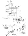
- Fig. 1 is a side elevation of a pick up hitch for mounting on a tractor, shown in a raised or towing position; .
- Fig. 2 is a front elevation of the pick-up hitch illustrated in Fig. 2;
- Fig 3 is a side elevation showing the pick-up hitch of Figs- 1 and 2 in a lowered position, fitted with an alternative draw bar to that illustrated in Figs 1 and 2,
- Figs 4 to 6 are views illustrating alternative forms of draw bar,
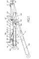
- Fig. 7 is a longitudinal section taken in side elevation of an alternative form of pick-up hitch according to the present invention including a trapezoidal linkage.
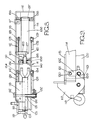
- Fig. 8 is a part sectional plan view of the pick-up hitch illustrated in Fig. 7, with parts removed for clarity, and
- Fig. 9 is a detail view of part of the hitch of Figs 7 and 8 showing a mechanical latch for retaining the hitch in a raised towing position.
- Referring now to Figs. 1 to 3, the towing hitch comprises principally a
fixed part 10, amovable part 11, and a link arrangement illustrated byarrow 12 interconnecting theparts - More particularly, the
fixed part 10 comprises a pair of mutually parallel L-section metal members tractor using bolts 15 passing through holes in the base flanges of the L-section metal members rotatable shaft 16 is supported by the other flanges of the L-section metal members rotatable shaft 16 extends through the other flange of themetal member 13 and has anarm 17 secured thereto. One end of acable 18 is secured to thearm 17 and runs through anouter sleeve 19 to a remote location to terminate in a handle (not shown) for operation by a driver of the tractor. Upward movement of thecable 18 causes rotation of theshaft 16 in an anticlockwise direction as viewed in Fig. 1. Mounted on theshaft 16 between and adjacent the said other flanges of themetal members keepers 20 which are locked to theshaft 16 so as to be rotatable therewith. - A pair of
helical torsion springs 21 are also mounted on theshaft 16. Eachtorsion spring 21 is anchored at one of its ends relative to thefixed part 10 and abuts against a respective one of thekeepers 20 at its other- end. The arrangement is such that thekeepers 20 are biassed into the positions illustrated in the drawings, by thetorsion springs 21 but can be moved in an anticlockwise direction as viewed in Fig. 1 by upward movement of thecable 18. - The
link arrangement 12 includes a pair oflower links shaft 16 but which are rotatable relative to the latter.. Thelower links plate 24 whose side edges are welded to therespective links plate 24 carries a pair of parallel, crankedarms 25 at whose free ends is carried ahorizontal bar 26 spanning thearms 25. Also mounted on theplate 24 is a pair oflatch members 27. Eachlatch member 27 is associated with a respective one of thekeepers 20. - The
link arrangement 12 also includes a pair ofupper links respective metal members respective pivot pins - The
movable part 11 comprises a pair of mutually parallel,vertical plates horizontal plates upper links pivot pins plates respective pivot pins lower links shaft 16 are connected with intermediate regions of theplates respective pivot pins 38 and 39. Thepivot pins pivot pins pivot pins 38 and 39. Thus, thefixed part 10,movable part 11, andlink arrangement 12 define a parallelogram linkage which is movable in the vertical plane. - The
horizontal plates draw bar 42 which is to be detachably engaged with the towing arm of a trailer. In Figs. 1 and 2, there is illustrated adraw bar 42 terminating in a hooked end for engaging a towing eye on the tow arm of the trailer. In Fig. 3 there is illustrated adraw bar 42 having a yoked end of which the upper arm of the yoke may be detached by unscrewing and removingfixing bolts 43. In Fig. 4, there is illustrated areversible draw bar 42 having a hook at one end and a simple connection at the other for engagement with a trailer arm having a yoked termination. It will be appreciated from the above that any one of the above describeddraw bars 42 may be mounted in themovable part 11 between thehorizontal plates section metal members upper locations 44 andlower locations 45 to enable the towing hitch to be used with a standard high level draw bar and a standard low level draw bar as illustrated in Figs. 5 and 6 respectively, where the required retaining pins and security clips are also illustrated. Such high and low level draw bars are fitted after detachment of thelinks fixed part 10. - The above described pick-up hitch can be operated by a pair of rams whose piston rods are pivotally connected with the respective
upper links hydraulic ram 47 may be provided which is connected with thelower links links draw bar 42 is in a lowered, rearward position relative to the forward direction of travel of the vehicle fitted with the hitch. When the rams are retracted, thelinks fixed part 10. In this position, thedraw bar 42 is in a raised position which is disposed forwardly (relative to the direction of forward travel of the vehicle) of the lowered position. In the raised position, thelatch members 27 rest against therespective keepers 20 so retaining the pick up hitch in its raised position. It will be seen from Figs. 1 and 2, that in the raised position, thebar 26 extends across the opening of the tow hook thus preventing the towing eye of the trailer from becoming inadvertently detached from the hook. When it is desired to lower the pick-up hitch, the tractor hydraulics are operated to lift themovable part 11 slightly so as to take the weight of the assembly off thekeepers 20. Retraction of thecable 18 can then be effected to pivot thekeepers 20 in an anticlockwise direction as illustrated in Fig. 1 so that themovable part 11 is free to drop when permitted to do so by the rams. - Referring now to Figs 7 to 9, the pick-up hitch illustrated therein is considered to be more suitable than the pick-up hitch of Fig. 1 in cases where operation of the hitch is required to be effected with a hydraulic ram which is in a similar location to ram 47 (see Fig. 1). The pick-up hitch of Figs. 7 to 9 has a
fixed part 110, amovable part 111 and a trapezoidal link arrangement illustrated byarrows 112 interconnecting theparts fixed part 112 comprises a pair of mutually parallelmetal side plates cross plate 115 and aforward end plate 116. Thecross plate 115 and a pair of further plates 117 (only one shown) are drilled to enable thefixed part 110 to be bolted to the underside of the tractor. At its rearward end, thefixed part 110 is fitted with a pair ofplates 118 and ahorizontal bar 119 whose purpose is the same as that described above forbar 26. - The
movable part 111 comprises a pair of mutuallyparallel plates 120 interconnected at their rear end portions by upper and lowertransverse plates 121 each provided with a pair of holes therein to receivepins 122 which pass through areversible draw bar 123 which is the same as draw bar 42 (Fig. 4). Theplates 121 are also interconnected intermediate their ends by an uppertransverse plate 124. - The
link arrangement 112 comprises a pair of mutually parallelforward links 125 and a pair of mutually parallelrearward links 126. Thelinks 125 are shorter than thelinks 126. The upper end of the forward links are pivotally connected with thefixed part 110 through the intermediary of acommon shaft 127. Theshaft 127 is fixed to the side plates -113 and 114 and passes through thelinks 125 and through abearing sleeve 128 which is secured to and interconnects the upper ends of thelinks 125. The assembly oflinks 125 andsleeve 128 are free to pivot about theshaft 127. The lower ends of thelinks 125 are pivotally attached to therespective plates 120 throughrespective stub axles 129. - The
rearward links 126 are pivotally mounted at their upper ends on abearing sleeve 130 which is secured at its ends in therespective side plates rotary shaft 131 extends through thesleeve 130 and has a hookedlatch element 132 secured to each end thereof externally of theside plates latch elements 132 are each arranged to engage with a respective boss 133 (only one shown) projecting laterally from therespective side plate 120. A spring loaded cable (not shown) is connected to one of thelatch elements 132 for resiliently urging thelatch elements 132 into the path of movement of therespective bosses 133. Remote operation of the cable by the driver is effected against the action of the spring to release thebosses 133. - The lower ends of the
rearward links 126 are pivotally attached to therespective plates 120 viastub axles 134. Intermediate their ends, thelinks 126 are interconnected by an uppertransverse reinforcing plate 135. - A
hydraulic ram 136 is pivotally mounted at its forward end between theside plates shaft 137. which is engaged in opposedshort sleeves 138 secured to the inner faces ofside plates end plate 116 by reinforcing flanges. The piston rod of theram 137 terminates in ahead 138 which is bored and sleeved to receive ashaft 139 engaging inshort sleeves 140 secured to theplates 120 by reinforcing flanges. - It will be appreciated from the above that the
fixed part 110, themovable part 111 and thelinks 125 define a trapezoidal linkage which enables themovable part 111 to be moved between a lowered position in which thepart 111 and a raised position by operation of theram 136. In its lowered position (as shown in dotted line in Fig 7), themovable part 111 is inclined at an acute angle relative to thefixed part 110 with its rearward end (i.e the end carrying the draw bar lower than its forward end because of the difference in lengths of thelevers movable part 111 moves downwardly and rearwardly. In its raised or towing position, themovable part 111 lies parallel to and partly inside the fixed part 110 (as shown in full line in Fig, 7). When being moved by theram 136 into its raised position, themovable part 111 moves upwardly and forwardly. During this movement, thebosses 133 engage the lower ends of thelatch elements 132 which are inclined so as to permit the latter to be pivoted against the action of the spring in the spring loaded cable so as to permit engagement of the bosses in the hooked portions of theelements 132. - When the
movable part 111 is to be lowered, theram 136 is retracted slightly so as to take the weight of themovable part 111 and lift it slightly so that thelatch elements 132 can be disengaged from theirrespective bosses 132 by pulling on the cable. Thereafter, the supply pressure to the ram is cut off leaving themovable part 111 to move under its own weight and under the weight of the trailer into its lowered position.
Claims (8)
Applications Claiming Priority (2)
| Application Number | Priority Date | Filing Date | Title |
|---|---|---|---|
| GB8326995 | 1983-10-07 | ||
| GB838326995A GB8326995D0 (en) | 1983-10-08 | 1983-10-08 | Towing hitches |
Publications (2)
| Publication Number | Publication Date |
|---|---|
| EP0138519A2 true EP0138519A2 (en) | 1985-04-24 |
| EP0138519A3 EP0138519A3 (en) | 1985-10-30 |
Family
ID=10549914
Family Applications (1)
| Application Number | Title | Priority Date | Filing Date |
|---|---|---|---|
| EP84306760A Withdrawn EP0138519A3 (en) | 1983-10-07 | 1984-10-04 | Towing hitches |
Country Status (3)
| Country | Link |
|---|---|
| EP (1) | EP0138519A3 (en) |
| DE (1) | DE138519T1 (en) |
| GB (1) | GB8326995D0 (en) |
Cited By (12)
| Publication number | Priority date | Publication date | Assignee | Title |
|---|---|---|---|---|
| EP0171666A1 (en) * | 1984-07-26 | 1986-02-19 | Deere & Company | Towing device for coupling a towed vehicle to a towing vehicle |
| GB2172037A (en) * | 1985-03-07 | 1986-09-10 | Econ Group Ltd | Improvements relating to mounting of snow ploughs |
| EP0346885A1 (en) * | 1988-06-16 | 1989-12-20 | Roman Johann Sauermann | Apparatus for attaching a trailer to a vehicle |
| WO1990006240A1 (en) * | 1988-11-28 | 1990-06-14 | Industri- Och Transportkonsult Ab | Traction device |
| GB2235120A (en) * | 1989-08-24 | 1991-02-27 | Patrick Mccormick | A hitch for a tractor |
| DE4208342C1 (en) * | 1992-03-16 | 1993-08-26 | Jean Walterscheid Gmbh, 5204 Lohmar, De | |
| EP0561192A1 (en) * | 1992-03-16 | 1993-09-22 | GKN Walterscheid GmbH | Traction device with an opening security |
| DE4238583A1 (en) * | 1992-11-16 | 1994-05-19 | Walterscheid Gmbh Gkn | Three-point tow-hitch system - is for agricultural tractor and has PTO inside triangle formed by tow-hitch linkage attachment points |
| DE4238584A1 (en) * | 1992-11-16 | 1994-05-19 | Walterscheid Gmbh Gkn | Lock for trailer coupling linkage on tractor - uses positioning cable connected to position indicator visible to driver and has safety lever positioned between both |
| EP1867499A1 (en) * | 2006-05-16 | 2007-12-19 | LH Lift Oy | Tow-hook arrangement and method for coupling an object to be towed to a mobile working machine |
| EP1876040A1 (en) | 2006-07-04 | 2008-01-09 | CBM S.p.A. | Tractor hitch for trailer |
| CN107225922A (en) * | 2017-08-01 | 2017-10-03 | 铽罗(上海)机器人科技有限公司 | The traction hook and its method of work of a kind of automatic guide vehicle hydraulic handjack |
Citations (6)
| Publication number | Priority date | Publication date | Assignee | Title |
|---|---|---|---|---|
| DE613541C (en) * | 1935-05-21 | Kadner & Co | Device for adjusting the height of one coupling member, especially for trailer couplings of motor vehicles | |
| US2725243A (en) * | 1953-05-18 | 1955-11-29 | William P Paulsen | Lifting drawbar for tractors |
| US3421779A (en) * | 1966-10-25 | 1969-01-14 | Earl E Shelby | Hitch device |
| US3450220A (en) * | 1967-04-04 | 1969-06-17 | Jack W Frandsen | Automatic drawbar hitch |
| US3863955A (en) * | 1970-08-26 | 1975-02-04 | Deere & Co | Pick-up-type drawbar assembly |
| GB2042316A (en) * | 1979-02-23 | 1980-09-24 | Kaitanen P | Tractor hitches |
-
1983
- 1983-10-08 GB GB838326995A patent/GB8326995D0/en active Pending
-
1984
- 1984-10-04 EP EP84306760A patent/EP0138519A3/en not_active Withdrawn
- 1984-10-04 DE DE1984306760 patent/DE138519T1/en active Pending
Patent Citations (6)
| Publication number | Priority date | Publication date | Assignee | Title |
|---|---|---|---|---|
| DE613541C (en) * | 1935-05-21 | Kadner & Co | Device for adjusting the height of one coupling member, especially for trailer couplings of motor vehicles | |
| US2725243A (en) * | 1953-05-18 | 1955-11-29 | William P Paulsen | Lifting drawbar for tractors |
| US3421779A (en) * | 1966-10-25 | 1969-01-14 | Earl E Shelby | Hitch device |
| US3450220A (en) * | 1967-04-04 | 1969-06-17 | Jack W Frandsen | Automatic drawbar hitch |
| US3863955A (en) * | 1970-08-26 | 1975-02-04 | Deere & Co | Pick-up-type drawbar assembly |
| GB2042316A (en) * | 1979-02-23 | 1980-09-24 | Kaitanen P | Tractor hitches |
Cited By (16)
| Publication number | Priority date | Publication date | Assignee | Title |
|---|---|---|---|---|
| EP0171666A1 (en) * | 1984-07-26 | 1986-02-19 | Deere & Company | Towing device for coupling a towed vehicle to a towing vehicle |
| GB2172037A (en) * | 1985-03-07 | 1986-09-10 | Econ Group Ltd | Improvements relating to mounting of snow ploughs |
| EP0346885A1 (en) * | 1988-06-16 | 1989-12-20 | Roman Johann Sauermann | Apparatus for attaching a trailer to a vehicle |
| WO1990006240A1 (en) * | 1988-11-28 | 1990-06-14 | Industri- Och Transportkonsult Ab | Traction device |
| GB2235120A (en) * | 1989-08-24 | 1991-02-27 | Patrick Mccormick | A hitch for a tractor |
| GB2235120B (en) * | 1989-08-24 | 1993-11-03 | Patrick Mccormick | A hitch for a tractor |
| DE4208343A1 (en) * | 1992-03-16 | 1993-09-23 | Walterscheid Gmbh Jean | TOWING DEVICE WITH OPENING LOCK |
| EP0561191A1 (en) * | 1992-03-16 | 1993-09-22 | GKN Walterscheid GmbH | Traction device |
| EP0561192A1 (en) * | 1992-03-16 | 1993-09-22 | GKN Walterscheid GmbH | Traction device with an opening security |
| DE4208342C1 (en) * | 1992-03-16 | 1993-08-26 | Jean Walterscheid Gmbh, 5204 Lohmar, De | |
| DE4238583A1 (en) * | 1992-11-16 | 1994-05-19 | Walterscheid Gmbh Gkn | Three-point tow-hitch system - is for agricultural tractor and has PTO inside triangle formed by tow-hitch linkage attachment points |
| DE4238584A1 (en) * | 1992-11-16 | 1994-05-19 | Walterscheid Gmbh Gkn | Lock for trailer coupling linkage on tractor - uses positioning cable connected to position indicator visible to driver and has safety lever positioned between both |
| EP1867499A1 (en) * | 2006-05-16 | 2007-12-19 | LH Lift Oy | Tow-hook arrangement and method for coupling an object to be towed to a mobile working machine |
| EP1876040A1 (en) | 2006-07-04 | 2008-01-09 | CBM S.p.A. | Tractor hitch for trailer |
| CN107225922A (en) * | 2017-08-01 | 2017-10-03 | 铽罗(上海)机器人科技有限公司 | The traction hook and its method of work of a kind of automatic guide vehicle hydraulic handjack |
| CN107225922B (en) * | 2017-08-01 | 2023-07-28 | 铽罗(上海)机器人科技有限公司 | Traction hook for automatically guiding vehicle oil hydraulic scooter and working method thereof |
Also Published As
| Publication number | Publication date |
|---|---|
| DE138519T1 (en) | 1985-09-26 |
| GB8326995D0 (en) | 1983-11-09 |
| EP0138519A3 (en) | 1985-10-30 |
Similar Documents
| Publication | Publication Date | Title |
|---|---|---|
| US3760883A (en) | Quick hitch assembly | |
| US4176727A (en) | Devices for automatically coupling implements to self-propelled articles | |
| US6478094B2 (en) | Hydraulic three point tractor hitch | |
| US4090725A (en) | Devices for automatically coupling implements to self-propelled vehicles | |
| US5692573A (en) | Towing Arrangement | |
| GB2037142A (en) | Tractor power lift linkages | |
| US4360215A (en) | Drill hitch transport | |
| US4431207A (en) | Automatic hitch device | |
| US2502805A (en) | Mower attachment for tractors | |
| EP0138519A2 (en) | Towing hitches | |
| US5286050A (en) | Hitch for trailers | |
| US3826517A (en) | Coupling device | |
| US3536340A (en) | Hinged assembly for coupling tractor and trailer | |
| US6193259B1 (en) | Mounting frame for use with three point hitch | |
| US2968494A (en) | Hitch device | |
| US3974880A (en) | Drawbar assembly | |
| US5215425A (en) | Tractor towing apparatus | |
| US4953883A (en) | Truck trailer hitch | |
| US2788227A (en) | Combination hitch and tongue support actuator | |
| US2805083A (en) | Hitch connections between tractive vehicles and devices trailed thereby using power means for lifting a coupling element | |
| EP0308271B1 (en) | Drawbar assembly | |
| US3022092A (en) | Power lift hitch mechanism | |
| US3347560A (en) | Swinging boom pressure control hitch | |
| GB2380720A (en) | Vehicle hitch | |
| EP2540149A1 (en) | Tractor implement hitch |
Legal Events
| Date | Code | Title | Description |
|---|---|---|---|
| PUAI | Public reference made under article 153(3) epc to a published international application that has entered the european phase |
Free format text: ORIGINAL CODE: 0009012 |
|
| AK | Designated contracting states |
Designated state(s): DE FR GB SE |
|
| EL | Fr: translation of claims filed | ||
| PUAL | Search report despatched |
Free format text: ORIGINAL CODE: 0009013 |
|
| DET | De: translation of patent claims | ||
| AK | Designated contracting states |
Designated state(s): DE FR GB SE |
|
| 17P | Request for examination filed |
Effective date: 19860212 |
|
| 17Q | First examination report despatched |
Effective date: 19861014 |
|
| R17C | First examination report despatched (corrected) |
Effective date: 19870330 |
|
| STAA | Information on the status of an ep patent application or granted ep patent |
Free format text: STATUS: THE APPLICATION IS DEEMED TO BE WITHDRAWN |
|
| 18D | Application deemed to be withdrawn |
Effective date: 19890419 |
|
| RIN1 | Information on inventor provided before grant (corrected) |
Inventor name: COOPER, DAVID JOHN |