EP0138425B1 - Fuel distribution and metering - Google Patents
Fuel distribution and metering Download PDFInfo
- Publication number
- EP0138425B1 EP0138425B1 EP84306461A EP84306461A EP0138425B1 EP 0138425 B1 EP0138425 B1 EP 0138425B1 EP 84306461 A EP84306461 A EP 84306461A EP 84306461 A EP84306461 A EP 84306461A EP 0138425 B1 EP0138425 B1 EP 0138425B1
- Authority
- EP
- European Patent Office
- Prior art keywords
- fuel
- reservoir
- tubes
- metering
- fine tubes
- Prior art date
- Legal status (The legal status is an assumption and is not a legal conclusion. Google has not performed a legal analysis and makes no representation as to the accuracy of the status listed.)
- Expired
Links
- 239000000446 fuel Substances 0.000 title claims description 109
- 239000000203 mixture Substances 0.000 claims description 13
- 238000012546 transfer Methods 0.000 claims description 9
- 230000006698 induction Effects 0.000 claims description 6
- 238000002485 combustion reaction Methods 0.000 claims description 5
- 238000005273 aeration Methods 0.000 claims description 4
- 230000005587 bubbling Effects 0.000 claims description 4
- 230000001419 dependent effect Effects 0.000 claims description 3
- 230000005484 gravity Effects 0.000 claims description 3
- 238000010438 heat treatment Methods 0.000 claims description 2
- 238000007598 dipping method Methods 0.000 claims 1
- 238000005086 pumping Methods 0.000 claims 1
- 238000002347 injection Methods 0.000 description 4
- 239000007924 injection Substances 0.000 description 4
- 230000001133 acceleration Effects 0.000 description 3
- 238000009736 wetting Methods 0.000 description 3
- 239000007788 liquid Substances 0.000 description 2
- 230000001052 transient effect Effects 0.000 description 2
- 238000010276 construction Methods 0.000 description 1
- 238000007796 conventional method Methods 0.000 description 1
- 238000013461 design Methods 0.000 description 1
- 238000001514 detection method Methods 0.000 description 1
- 239000000839 emulsion Substances 0.000 description 1
- 239000012530 fluid Substances 0.000 description 1
- 235000003642 hunger Nutrition 0.000 description 1
- 238000005259 measurement Methods 0.000 description 1
- 238000000034 method Methods 0.000 description 1
- 230000000116 mitigating effect Effects 0.000 description 1
- 238000004513 sizing Methods 0.000 description 1
- 230000037351 starvation Effects 0.000 description 1
- 230000001360 synchronised effect Effects 0.000 description 1
- XLYOFNOQVPJJNP-UHFFFAOYSA-N water Substances O XLYOFNOQVPJJNP-UHFFFAOYSA-N 0.000 description 1
Images
Classifications
-
- F—MECHANICAL ENGINEERING; LIGHTING; HEATING; WEAPONS; BLASTING
- F02—COMBUSTION ENGINES; HOT-GAS OR COMBUSTION-PRODUCT ENGINE PLANTS
- F02M—SUPPLYING COMBUSTION ENGINES IN GENERAL WITH COMBUSTIBLE MIXTURES OR CONSTITUENTS THEREOF
- F02M17/00—Carburettors having pertinent characteristics not provided for in, or of interest apart from, the apparatus of preceding main groups F02M1/00 - F02M15/00
- F02M17/18—Other surface carburettors
- F02M17/26—Other surface carburettors with other wetted bodies
- F02M17/28—Other surface carburettors with other wetted bodies fuel being drawn through a porous body
-
- F—MECHANICAL ENGINEERING; LIGHTING; HEATING; WEAPONS; BLASTING
- F02—COMBUSTION ENGINES; HOT-GAS OR COMBUSTION-PRODUCT ENGINE PLANTS
- F02M—SUPPLYING COMBUSTION ENGINES IN GENERAL WITH COMBUSTIBLE MIXTURES OR CONSTITUENTS THEREOF
- F02M19/00—Details, component parts, or accessories of carburettors, not provided for in, or of interest apart from, the apparatus of groups F02M1/00 - F02M17/00
- F02M19/02—Metering-orifices, e.g. variable in diameter
- F02M19/0242—Metering-orifices, e.g. variable in diameter with inserts of porous material
Definitions
- the invention relates to the distribution and metering of fuel to the cylinders of a multicylinder internal combustion engine.
- a fuel injection system has the advantage that the metering of the fuel is performed separately from the metering of the air supply to the cylinders.
- the mixture strengths for the cylinders may be adjusted individually permitting more accurate control.
- the intake manifold design is simplified and the manifold is dry, which facilitates tuning of the manifold length and avoids the various problems caused by fuel in the manifold which tends to be deposited on the walls of the manifold and disturbs the mixture strength under transient conditions.
- the chief disadvantage of fuel injection is the complexity, which is reflected in the cost and in reliability.
- a fuel metering and distribution system for an internal combustion engine is known from DE-A-2 639 920 which comprises an open fuel reservoir, metering means for introducing fuel into the reservoir at a controlled rate dependent upon the rate of air flow to engine cylinders, and a plurality of fine tubes each for transferring fuel from the fuel reservoir to a point adjacent the intake valve of a respective one of the engine cylinders.
- the present invention provides a fuel metering and distribution system for an internal combustion engine comprising an open fuel reservoir, metering means which introduces fuel into the reservoir at a controlled rate dependent upon the rate of air flow to engine cylinders, and a plurality of fine tubes each for transferring fuel from the fuel reservoir to a point adjacent the intake valve of a respective one of the engine cylinders, characterised in that the ends of the fine tubes are disposed in the reservoir and terminate at the same predetermined level in the reservoir, whereby as fuel is metered by the metering means into the reservoir, the fuel level rises above said predetermined level and the additional fuel metered into the reservoir is sucked into the fine tubes and transferred directly to the engine cylinders.
- the fuel introduced at a controlled rate into the reservoir acts to raise the fuel level and the fine tubes which are under vacuum pressure draw the fuel so that once the fuel level in the reservoir attains equilibrium, all the fuel introduced into the reservoir is drawn by the intake manifold vacuum through the fine tubes to the cylinders while by-passing the air intake manifold.
- the fine tubes cannot however suck any more fuel than is metered into the reservoir.
- the cylinders draw equal amounts of fuel from the. reservoir without affecting the fuel metering function.
- the pressure cycles of the cylinders are not synchronised, one cylinder may draw more of the metered fuel than the other cylinders.
- the vacuum pressure in the manifold is suffi- cientto suck all the fuel from the reservoir without assistance under most operating conditions.
- the reservoir is also preferable, for the same reason, to arrange the reservoir at a level higher than the exit ends of the fine tubes so that gravity assists in the transfer by siphoning action.
- the tubes may be heated, such as by means of a water jacket or routing them adjacent the exhaust manifold. Such heating also vaporises the fuel to improve combustion in the engine cylinders.
- a perforated collar which dips below the fuel level and surrounds the ends of the fine tubes.
- the suction by the tubes in the perforated collar causes aeration and bubbling of the fuel and the fuel drawn through the fine tubes is mixed with air. Because the ends of the fine tubes need not now dip below the fuel level in the reservoir, there is no danger of uneven distribution through one fine tube drawing air the metered fuel and preventing the fuel level from reaching the remaining tubes.
- the metering of fuel into the reservoir may be achieved by means of a conventional venturi in the intake manifold causing fuel to be drawn into the reservoir from a float chamber by way of a main metering jet.
- the metering may be performed by the conventional method used in carburettors thereby offering the advantage of few moving parts which makes for a cheaper and more reliable system.
- the fuel is however distributed separately to each individual cylinder and if desired the mixture strengths may be balanced by jets in the fine tubes.
- fuel may be metered to the reservoir by means of a common solenoid valve, which retains the electronic control of fuel injection systems over the mixture strength while considerably simplifying the construction.
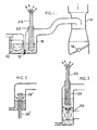
- a metering system comprises a float chamber 10 which is similar to the float chamber of a conventional carburettor.
- a reservoir 18 is connected to the float chamber 10 by way of a main metering jet 12 and the reservoir 18 is connected to a venturi 14 in an air induction passage of the engine controlled by a butterfly valve 16.
- the metering system illustrated in Figure 1 is of a basic nature and is shown only to demonstrate the principle of operation. It will be clear that more advanced features of conventional carburettors, such as an acceleration pump, air bleed and emulsion tubes, a power valve, a choke etc., may also be incorporated, the essential difference being that the metered fuel is intercepted before being mixed with the air and is instead introduced into the reservoir 18 for transfer by means of the capillary tubes 20 directly to the intake valves of the cylinders.
- carburettors such as an acceleration pump, air bleed and emulsion tubes, a power valve, a choke etc.
- a conventional carburettor In a conventional carburettor, the fuel metered to the engine during idling is not effected by means of the main jet but by a separate idling circuit which is sensitive to air flow in the vicinity . of the butterfly valve. In adapting such a carburetor for multi-point fuel distribution during idling and normal running, it is necessary to provide two reservoirs, the first having fuel metered to it by the main jet and the second by the idling jet. In other words, any means employed in a conventional carburetor to meter fuel may be adapted for multi-point fuelling as proposed by the invention.
- the fuel from the reservoir 18 does not pass directly into the inducted air but is instead injected towards the end of the induction manifold adjacent the intake valves by means of the capillary tubes 20.
- the capillary tubes 20 terminate at a short distance above the fuel level in "the fuel reservoir 18 and are surrounded by a perforated collar 22 which dips into the fuel.
- the tubes 20 open into the intake manifold and venturis are formed in the manifold in order to increase the vacuum pressure in the capillary tubes 20. Because of the high vacuum pressure in the capillary tubes 20, fluid is constantly sucked into the tubes and this reduces the pressure within the collar 20. As a result, air enters into the collar causing bubbling and aeration of the fuel and an air and fuel mixture reaches the level of the openings of all of the capillary tubes 20. Consequently, fuel is sucked into the tubes and delivered directly to the respective cylinders while by-passing the intake manifold.
- An advantage of by-passing the intake manifold is that the manifold is dry and the problems caused by wall wetting are avoided.
- the fuel on the walls of the manifold does not affect fuel metering under steady state conditions but gives rise to a hysteresis problem as a new equilibrium has to be arrived at when the engine load alters. For example, when the throttle is closed the manifold walls are dry but if the throttle is suddenly opened the fuel is used to re-wet the manifold instead of being burned in the cylinders.
- This is usually overcome by the use of an acceleration pump but in the present invention such a pump, if present in the metering system, may be reduced capacity.
- the vacuum in the capillary tubes is usually sufficient to transport the fuel to the intake ports of the cylinders but because of the small diameter of the tubes the air quantity that is also sucked through the tubes is not great and does not interfere unduly with the metering of the fuel by the pressure signal from the metering venturi in the induction passage.
- a problem which one might expect with the system of the invention is fuel starvation at high load since the vacuum pressure drops as the fuel requirement rises.
- the earlier described venturis are formed in the intake manifold at the end of the capillary tubes and additionally the reservoir 18 is arranged at a higher level than the intake manifold so that the fuel transfer is assisted by gravity.
- the density of fuel in the capillary tubes increases automatically because of reduced aeration and as a result the efficiency of the siphoning action -improves when it is most needed.
- the capillary tubes may be heated to vaporise the fuel and if necessary a pump may be employed to drive the air-fuel mixture along the tubes.
- the tubes 20 are shown in Figure 1 as arranged above the liquid level but in the alternative embodiment of the two the tubes 20' enter the reservoir from beneath and it is only the ends of the capillary tubes which lie above the liquid level.
- the operation of this embodiment is otherwise similar to that in Figure 1 and a perforated collar 22' is still employed to cause bubbling at the air to fuel interface.
- the fuel is metered into the reservoir 18 by a carburettor-like arrangement and all fuel entering the reservoir 18 is eventually transferred to the respective cylinders.
- electronic metering may be employed while still relying on the vacuum pressure to transfer th& * fuel to the individual cylinders and this is achieved in the embodiment of Figure 3 by means of a solenoid valve 30 which is arranged between the reservoir and a source of fuel under high pressure, the solenoid 30 serving to meter controlled quantities of fuel to the reservoir.
- capillary tubes are used to transfer fuel, it is possible if desired to control the fuel distribution between cylinders by differently sizing the capillary tubes 20 so as to vary the resistance to fuel flow in the different tubes.
Landscapes
- Engineering & Computer Science (AREA)
- Chemical & Material Sciences (AREA)
- Combustion & Propulsion (AREA)
- Mechanical Engineering (AREA)
- General Engineering & Computer Science (AREA)
- Dispersion Chemistry (AREA)
- Fuel-Injection Apparatus (AREA)
- Measuring Volume Flow (AREA)
- Electrical Control Of Air Or Fuel Supplied To Internal-Combustion Engine (AREA)
- Cooling, Air Intake And Gas Exhaust, And Fuel Tank Arrangements In Propulsion Units (AREA)
Applications Claiming Priority (2)
| Application Number | Priority Date | Filing Date | Title |
|---|---|---|---|
| GB08326023A GB2147365A (en) | 1983-09-28 | 1983-09-28 | I c engine fuel distribution and metering |
| GB8326023 | 1983-09-28 |
Publications (3)
| Publication Number | Publication Date |
|---|---|
| EP0138425A2 EP0138425A2 (en) | 1985-04-24 |
| EP0138425A3 EP0138425A3 (en) | 1987-04-15 |
| EP0138425B1 true EP0138425B1 (en) | 1990-03-07 |
Family
ID=10549447
Family Applications (1)
| Application Number | Title | Priority Date | Filing Date |
|---|---|---|---|
| EP84306461A Expired EP0138425B1 (en) | 1983-09-28 | 1984-09-21 | Fuel distribution and metering |
Country Status (8)
| Country | Link |
|---|---|
| US (1) | US4567871A (ja) |
| EP (1) | EP0138425B1 (ja) |
| JP (1) | JPS60502266A (ja) |
| AU (1) | AU573283B2 (ja) |
| BR (1) | BR8407051A (ja) |
| DE (1) | DE3481534D1 (ja) |
| GB (1) | GB2147365A (ja) |
| WO (1) | WO1985001549A1 (ja) |
Families Citing this family (3)
| Publication number | Priority date | Publication date | Assignee | Title |
|---|---|---|---|---|
| US5082184A (en) * | 1986-05-02 | 1992-01-21 | General Motors Corporation | Fuel injection |
| GB2193536A (en) * | 1986-08-04 | 1988-02-10 | Ford Motor Co | I.c. engine fuel metering and distribution system |
| US5482024A (en) * | 1989-06-06 | 1996-01-09 | Elliott; Robert H. | Combustion enhancer |
Family Cites Families (18)
| Publication number | Priority date | Publication date | Assignee | Title |
|---|---|---|---|---|
| US1365661A (en) * | 1916-07-19 | 1921-01-18 | Joseph C Coulombe | Suction-inducing and fuel-feeding device |
| GB269470A (en) * | 1926-04-14 | 1927-10-31 | Charles Henri Claudel | Improvements in spray-carburettors for internal-combustion engines |
| GB278425A (en) * | 1926-07-05 | 1927-10-05 | Robert Owen King | Improvements in or relating to carburetting apparatus for internal combustion engines |
| FR652789A (fr) * | 1927-09-30 | 1929-03-13 | Perfectionnements aux carburateurs pour moteurs à combustion interne | |
| US1791204A (en) * | 1928-06-21 | 1931-02-03 | Harel Lucien | Carburetor |
| US1845668A (en) * | 1930-02-26 | 1932-02-16 | Charles G Keil | Carburetor |
| FR784824A (fr) * | 1934-12-15 | 1935-07-25 | Carburateur | |
| IT454095A (ja) * | 1948-10-30 | |||
| US3273809A (en) * | 1963-04-22 | 1966-09-20 | Bauer Bros Co | Refiner seal |
| US3419251A (en) * | 1965-06-21 | 1968-12-31 | Us Stoneware Inc | Distributor |
| DE2235146C2 (de) * | 1972-07-18 | 1982-06-03 | Robert Bosch Gmbh, 7000 Stuttgart | Kraftstoffzumeßanlage |
| FR2226010A5 (ja) * | 1972-09-28 | 1974-11-08 | Peugeot & Renault | |
| DE2639920A1 (de) * | 1976-09-04 | 1978-03-09 | Volkswagenwerk Ag | Kraftstoff-einspritzeinrichtung |
| DE2737849C2 (de) * | 1977-08-23 | 1984-11-29 | Volkswagenwerk Ag, 3180 Wolfsburg | Mehrzylindrige Otto-Brennkraftmaschine |
| JPS54177419U (ja) * | 1978-06-02 | 1979-12-14 | ||
| DE2900459A1 (de) * | 1979-01-08 | 1980-07-17 | Volkswagenwerk Ag | Einrichtung zur kontinuierlichen einspritzung eines aus kraftstoff und luft bestehenden gemisches in die ansaugleitung einer brennkraftmaschine |
| SU826063A1 (en) * | 1979-08-02 | 1981-04-30 | Mo Avtomobilnyj Zavod Im I A L | I.c.engine supply system |
| US4399794A (en) * | 1981-10-29 | 1983-08-23 | Gagnon David C | Carburetion system |
-
1983
- 1983-09-28 GB GB08326023A patent/GB2147365A/en not_active Withdrawn
-
1984
- 1984-08-27 AU AU35538/84A patent/AU573283B2/en not_active Ceased
- 1984-09-21 EP EP84306461A patent/EP0138425B1/en not_active Expired
- 1984-09-21 DE DE8484306461T patent/DE3481534D1/de not_active Expired - Lifetime
- 1984-09-27 US US06/661,335 patent/US4567871A/en not_active Expired - Fee Related
- 1984-09-27 JP JP59503817A patent/JPS60502266A/ja active Pending
- 1984-09-27 WO PCT/US1984/001567 patent/WO1985001549A1/en unknown
- 1984-09-27 BR BR8407051A patent/BR8407051A/pt unknown
Also Published As
| Publication number | Publication date |
|---|---|
| GB8326023D0 (en) | 1983-11-02 |
| EP0138425A2 (en) | 1985-04-24 |
| EP0138425A3 (en) | 1987-04-15 |
| US4567871A (en) | 1986-02-04 |
| AU573283B2 (en) | 1988-06-02 |
| JPS60502266A (ja) | 1985-12-26 |
| BR8407051A (pt) | 1985-08-13 |
| AU3553884A (en) | 1985-04-23 |
| DE3481534D1 (de) | 1990-04-12 |
| GB2147365A (en) | 1985-05-09 |
| WO1985001549A1 (en) | 1985-04-11 |
Similar Documents
| Publication | Publication Date | Title |
|---|---|---|
| US3931814A (en) | Cylinder-induction responsive electronic fuel feed control carburetors | |
| US3713630A (en) | Multicylinder carburetor | |
| CA1209869A (en) | Fuel priming system with integral auxilliary enrichment feature | |
| US4268462A (en) | Variable venturi carburetor | |
| US4499887A (en) | Dual fuel supply system | |
| GB501651A (en) | Improvements in carburetters for internal combustion engines | |
| US4368714A (en) | Fuel injection apparatus | |
| EP0138425B1 (en) | Fuel distribution and metering | |
| US3841613A (en) | Fuel metering device for internal combustion engines | |
| US4329964A (en) | Liquid fuel carburetion system | |
| US3125084A (en) | Fuel injection system | |
| US4182294A (en) | Apparatus for injecting fuel into a multi-cylinder internal combustion engine having a supercharging compressor | |
| US2635625A (en) | Fuel supply device | |
| CA1155015A (en) | Electronic controlled carburetor | |
| US2418011A (en) | Antipercolator structure for carburetors | |
| US3030085A (en) | Fuel circuits for air-bled carburetor | |
| CA1232174A (en) | Fuel distribution and metering | |
| US2768819A (en) | Engine fuel system | |
| US4387063A (en) | Carburettors comprising a main fuel circuit and an auxiliary circuit | |
| US3472494A (en) | Carburetor fuel supply system | |
| US4500476A (en) | Variable venturi type carburetor | |
| US2482102A (en) | Antidetonant liquid injection apparatus | |
| US2681214A (en) | Charge forming device | |
| US3544082A (en) | Fluidic fuel metering system | |
| US2882879A (en) | Fuel injection systems |
Legal Events
| Date | Code | Title | Description |
|---|---|---|---|
| PUAI | Public reference made under article 153(3) epc to a published international application that has entered the european phase |
Free format text: ORIGINAL CODE: 0009012 |
|
| AK | Designated contracting states |
Designated state(s): BE DE FR GB IT NL SE |
|
| PUAL | Search report despatched |
Free format text: ORIGINAL CODE: 0009013 |
|
| AK | Designated contracting states |
Kind code of ref document: A3 Designated state(s): BE DE FR GB IT NL SE |
|
| 17P | Request for examination filed |
Effective date: 19870928 |
|
| 17Q | First examination report despatched |
Effective date: 19881130 |
|
| GRAA | (expected) grant |
Free format text: ORIGINAL CODE: 0009210 |
|
| AK | Designated contracting states |
Kind code of ref document: B1 Designated state(s): BE DE FR GB IT NL SE |
|
| ITF | It: translation for a ep patent filed | ||
| REF | Corresponds to: |
Ref document number: 3481534 Country of ref document: DE Date of ref document: 19900412 |
|
| ET | Fr: translation filed | ||
| PG25 | Lapsed in a contracting state [announced via postgrant information from national office to epo] |
Ref country code: DE Effective date: 19900731 |
|
| PG25 | Lapsed in a contracting state [announced via postgrant information from national office to epo] |
Ref country code: GB Effective date: 19900921 |
|
| PG25 | Lapsed in a contracting state [announced via postgrant information from national office to epo] |
Ref country code: SE Effective date: 19900922 |
|
| PG25 | Lapsed in a contracting state [announced via postgrant information from national office to epo] |
Ref country code: BE Effective date: 19900930 |
|
| PLBE | No opposition filed within time limit |
Free format text: ORIGINAL CODE: 0009261 |
|
| STAA | Information on the status of an ep patent application or granted ep patent |
Free format text: STATUS: NO OPPOSITION FILED WITHIN TIME LIMIT |
|
| 26N | No opposition filed | ||
| BERE | Be: lapsed |
Owner name: FORD MOTOR CY LTD Effective date: 19900930 |
|
| PG25 | Lapsed in a contracting state [announced via postgrant information from national office to epo] |
Ref country code: NL Effective date: 19910401 |
|
| GBPC | Gb: european patent ceased through non-payment of renewal fee | ||
| NLV4 | Nl: lapsed or anulled due to non-payment of the annual fee | ||
| PG25 | Lapsed in a contracting state [announced via postgrant information from national office to epo] |
Ref country code: FR Effective date: 19910530 |
|
| REG | Reference to a national code |
Ref country code: FR Ref legal event code: ST |
|
| EUG | Se: european patent has lapsed |
Ref document number: 84306461.9 Effective date: 19910527 |