EP0138236A2 - Sectional false floor - Google Patents
Sectional false floor Download PDFInfo
- Publication number
- EP0138236A2 EP0138236A2 EP84200758A EP84200758A EP0138236A2 EP 0138236 A2 EP0138236 A2 EP 0138236A2 EP 84200758 A EP84200758 A EP 84200758A EP 84200758 A EP84200758 A EP 84200758A EP 0138236 A2 EP0138236 A2 EP 0138236A2
- Authority
- EP
- European Patent Office
- Prior art keywords
- tile
- receptacle
- floor
- edge
- zones
- Prior art date
- Legal status (The legal status is an assumption and is not a legal conclusion. Google has not performed a legal analysis and makes no representation as to the accuracy of the status listed.)
- Withdrawn
Links
Images
Classifications
-
- E—FIXED CONSTRUCTIONS
- E04—BUILDING
- E04F—FINISHING WORK ON BUILDINGS, e.g. STAIRS, FLOORS
- E04F15/00—Flooring
- E04F15/02—Flooring or floor layers composed of a number of similar elements
- E04F15/024—Sectional false floors, e.g. computer floors
- E04F15/02405—Floor panels
- E04F15/02417—Floor panels made of box-like elements
- E04F15/02423—Floor panels made of box-like elements filled with core material
- E04F15/02429—Floor panels made of box-like elements filled with core material the core material hardening after application
-
- E—FIXED CONSTRUCTIONS
- E04—BUILDING
- E04F—FINISHING WORK ON BUILDINGS, e.g. STAIRS, FLOORS
- E04F15/00—Flooring
- E04F15/02—Flooring or floor layers composed of a number of similar elements
- E04F15/024—Sectional false floors, e.g. computer floors
- E04F15/02405—Floor panels
- E04F15/02435—Sealing joints
-
- E—FIXED CONSTRUCTIONS
- E04—BUILDING
- E04F—FINISHING WORK ON BUILDINGS, e.g. STAIRS, FLOORS
- E04F15/00—Flooring
- E04F15/02—Flooring or floor layers composed of a number of similar elements
- E04F15/024—Sectional false floors, e.g. computer floors
- E04F15/02447—Supporting structures
- E04F15/02464—Height adjustable elements for supporting the panels or a panel-supporting framework
- E04F15/0247—Screw jacks
Definitions
- the invention relates to a floating floor construction comprising adjoining floor slabs supported at the angular points by so-called adjusting feet by means of which the floating floor rests on the subfloor, use being made of separation cross fittings.
- the adjusting foot in a floating floor construction as described in the above which foot is provided in a known manner with a base plate mountable onto the subfloor without attachment means, is a screwed spindle with nut and a platform having on the underside a bush fitting over the screwed spindle and resting on the nut, said base plate according to the invention being fitted with a central dishing for receiving the screwed spindle, while the plate portion around the central dishing is provided with radial, downwardly embossed zones having depths increasing towards the edge of the plt-ein such a manner that the adjusting foot, in unloaded condition, rests on embossed zones and in loaded condition the supporting function is taken over by the underside of the central dishing, which is provided with a two-sided adhesive layer.
- Such a design of the base of the adjusting foot has the advantage that, unlike a flat base plate, it is much less responsive to local irregularities in the subfloor area, for in unloaded condition, the support on a restricted number of spaced points underneath the embossed plate portions ensures stabilisation with fixation by the two-sided adhesive layer, while in loaded condition the plate can deflect, with the bottom of the central dishing taking over the compressive load.
- the adjusting feet according to the invention can be consequently quickly positioned with minimum preparatory steps.
- the platform with the bush can be placed over the screwed spindle and for a quick fixation of the platform on the screwed spindle according to the invention the bush may be provided in cross-section with flat sides with an interspace substantially equal to the outside dimension of the screwed spindle, which is enlarged at least at one location by deformation.
- the platform can be anchored onto the screwed spindle by rotation.
- the platform according to the invention can be formed by a metal receptacle filled as far as the upper edge with an elastomer, e.g. a sheet of synthetic rubber having a Shore hardness of 60-80.
- the material of the receptacle will deflect under the influence of a vertical load exerted thereon, so that the elastomer sheet takes over at least a part of the load, thus resiliently supporting the floor panels.
- the floor panels according to the invention are kept interspaced by using a known per se separation fitting, e.g. a cross to be placed on the platform, the sound vibrations will be damped, since the trajectory of a vibration from one panel to an adjoining panel extends substantially through the elastomer.
- the invention also concerns a floor panel in the form of a tile comprising a metal receptacle having a bottom and upright edges with a short outwardly directed circumferential flange at the upper edge, which receptacle is filled as far as the upper edge with a compression resistant material, in particular concrete.
- a metal receptacle filled with compression resistant material is that the metal receptacle can function as an external reinforcement taking up tensile stresses.
- the interspace of the tiles is so small that the mostly viscous adhesive mass bridges this interpace without any difficulty.
- the edge flanges thereof can function as knife guides for cutting the carpet.
- the edge flanges of the tile receptacles may be rounded at the angular points. This facilitates the insertion of a knife between two tiles, while an engagement possibility is created at each angular point for lifting a tile without pulling up the latter on the carpet, which may lead to damage to the carpet which remains visible after the tile has been replaced in position.
- An aid for minimizing the visibility of the unavoidable damage to the carpet during the cutting of a tile is a carpet knife having a handle and a cutting blade fitted according to the invention with a guide attached to the handle and extending into the cutting plane at the cutting edge side of the knife.
- the floor tile comprising a metal receptacle with compression resistant filling
- a favourable design is that in which the metal receptacle has the maximum depth in the angular zones, outside the angular zones the receptacle depth decreases abruptly and the receptacle bottom, except for discontinuities, extends substantially horizontally at a level lying at about 1/3 of the receptacle depth, while halfway two angular zones the receptacle bottom with raised portions links up approximately with the configuration of one half of a truncated cone with the receptacle sidevall in question.
- passages have to be made at several places to the subjacent cable space. Adjacent the "apices" of the truncated cones, the thickness of the material of the floor tiles is minimal (e.g. in the order of 8 mm of concrete) and a passage can be made with comparatively light material.
- the horizontal bottom portion may be discontinued by a raSed portion having the shape of a segment of a sphere, while radially embossed zones of outwardly increasing depth extend according to the tile diagonals from adjacent the sphere segment into the angular zones.
- Additional reinforcing ribs can be formed in the concrete arch by fitting the tile receptacle with dishings disposed between the central sphere segment and each of the truncated cones, extending parallel to the respective tile edges, said dishings having such depths that, when cutting a tile for placement at an edge of a floor construction, the sub-tile with the rib formed by a dishing can rest on a molding or the like edge support.
- adjusting feet 1 are used for supporting floor panels in the form of tiles 2 spaced above a subfloor 3.
- Each adjusting foot 1 supports a plurality of tile angular points, use being made of a separation fitting 4, e.g. at four tile angular points one separation cross.
- a carpet 5 can be installed on the floating floor formed by the tiles 2 by means of an adhesive layer, not shown.
- the adjusting foot 1 is composed of a base plate 6, a screwed spindle 7 with thereon a nut 8 adjustable in height and defining the local level of the floating floor, as well as a platform 9 on which tile angular points 2 are supported.
- the base plate comprises a central dishing 10 with downwardly embossed portions 11 starting thereform and distributed circumferentially, having dephts increasing towards the edge of the plate 6 to such a value that in unloaded condition and placed on a flat bottom, the base plate rests exclusively on the embossed portions 11 and the under-side of the central dishing 10 is clear of the bottom.
- the tile carrier platform 9 comprises a metal receptacle 13 with upright side edges, which is filled with an elastomer 14 as far as the top level of the edges.
- a bush 14 having a rectangular cross-section in the embodiment shown (see Fig. 2) dimensioned in such a manner that the shortest distance between opposite sides is approximately equal to the outside dimension of the screwed spindle 7.
- the screw thread of the spindle 7 there are disposed local deformations 16 that project beyond the screw thread.
- the floating floor tiles 2 are positioned by means of separation crosses 4 and as a result of their weight, the base plate 6 of the adjusting foot 1 is deformed in the sense that, while so far the weight of the adjusting foot had been taken up by the downwardly embossed zones 11, the weight of the tiles 2 comes to rest directly on the subfloor 3 via the bush 14 and the screwed spindle 7 via the dishing 10 and the two-sided adhesive layer 12.
- the floor tiles 2 each comprise a metal receptacle 17 having a bottom 18, upright walls 19 with a circumferential flange 20 at the upper edge of each.
- the receptacle is filled with compression resistant material 21 such as concrete as far as the level of the circumferential flange 20.
- the tiles 2 are positioned by means of the separation fittings 4 in such a manner on the platforms 9 of the adjusting feet 1 that a space is provided between facing edge flanges 20, however only along a limited distance, in the orderof 1-3 mm. This slight interspace between adjoining tiles enables to apply a continuous adhesive layer on a mounted floating floor for a continuous carpet 5.
- a tile lifting tool can be inserted in the space created at the angular points by the roundings 22.
- the space between adjoining edge flanges 20 may serve for guiding a knife by means of which the carpet above the tile to be lifted can be cut.
- a knife shown in Fig. 5 which is fitted with a handle 28, a blade 29 and a guide 30 attached to the handle 28 and extending into the cutting plane.
- the guide ensures a separation between carpet piles, which consequently are not cut by the knife, so that during the subsequent replacement of a lifted tile, the carpet adhered thereto links up again entirely with surrounding carpet portions.
- the under-side of the metal receptacle 17 of each tile 2 has an arch shape, with arch legs at the angular points.
- the deepest portions of the metal receptacle are present in the angular zones 23 and the receptacle bottom 18 has a plurality df raised portions.
- the receptacle bottom is raised with portions 24 having substantially the configuration of one half of a truncated cone, by means of which the receptacle bottom between two angular zones 23 links up with the respective receptacle sidewall 19.
- a raised portion 25 having the shape of a sphere segment and from the central zone there extend radial, downwardly embossed zones 26 terminating in the angular zones 23.
- the radial dishings 26 form on the one end guides for concrete poured in the middle of the receptacle to the recessed angular zones 23 and on the other end radial reinforcing ribs are formed in the concrete mass in the dished portions 26.
- the metal receptacle 17 is also fitted with dishings 27 extending between the central raised portion 25 and the wall elevations 24, parallel to the respective receptacle walls 19, by means of which reinforcing ribs can also be formed in the concrete mass, the vertical dimensions of said ribs can be selected in such a manner that if only use is made of a part of a floating floor tile, e.g. along an edge of a floating floor, the respective tiles with a rib thus formed can rest in a dishing 27 on an edge supporting molding of the room.
- the floating floor construction according to the invention has a number of highly favourable properties when in use.As already observed, it is possible to apply a carpet or other fixed floor covering by means of a continuous adhesive layer in the same manner as on a continuous floot area not composed of tiles or such like panels.
Abstract
@ A floating floor construction comprising adjoining floor slabs which are supported at the angular points by adjusting feet by means of which the floating floor rests on the subfloor, the adjusting foot being provided with a base plate, a screwed spindle with nut and a platform having on the under-side a bush fitting over the screwed spindle and resting on the nut. The base plate is fitted with a central dishing for receiving the screwed spindle, while the plate portion around the central dishing is provided with radial, downwardly embossed zones having depths increasing towards the edge of the plate. The arrangement is such that the adjusting foot can be placed on the subfloor without attachment means, resting in unloaded condition on embossed zones of the base plate and in loaded condition the supporting function is taken over by the under-side of the central dishing provided with a two-sided adhesive layer.
Description
- The invention relates to a floating floor construction comprising adjoining floor slabs supported at the angular points by so-called adjusting feet by means of which the floating floor rests on the subfloor, use being made of separation cross fittings.
- It is the object of the invention to provide such a floor construction which, in addition to being placeable at high speed and in a simple manner, has favourable properties when in use, i.e. being slightly resilient, no special features being required for carpeting the floating floor by means of adhesive, and this can be effected in the same manner as on an even, concrete floor, an inhibiting effect is exerted on the propagation of sound vibrations, a carpet on the floating floor is automatically earthed electrically and likewise the accessibility to the space underneath the floating floor is optimum, viz. the lifting of a tile with the superimposed carpet portion can be effected with minimal steps and with minimal visible discontinuity of the carpet.
- In connection with the ease of installation, the adjusting foot in a floating floor construction as described in the above, which foot is provided in a known manner with a base plate mountable onto the subfloor without attachment means, is a screwed spindle with nut and a platform having on the underside a bush fitting over the screwed spindle and resting on the nut, said base plate according to the invention being fitted with a central dishing for receiving the screwed spindle, while the plate portion around the central dishing is provided with radial, downwardly embossed zones having depths increasing towards the edge of the plt-ein such a manner that the adjusting foot, in unloaded condition, rests on embossed zones and in loaded condition the supporting function is taken over by the underside of the central dishing, which is provided with a two-sided adhesive layer. Such a design of the base of the adjusting foot has the advantage that, unlike a flat base plate, it is much less responsive to local irregularities in the subfloor area, for in unloaded condition, the support on a restricted number of spaced points underneath the embossed plate portions ensures stabilisation with fixation by the two-sided adhesive layer, while in loaded condition the plate can deflect, with the bottom of the central dishing taking over the compressive load.
- The adjusting feet according to the invention can be consequently quickly positioned with minimum preparatory steps. After the level adjustment by means of the nut on the screwed spindle, the platform with the bush can be placed over the screwed spindle and for a quick fixation of the platform on the screwed spindle according to the invention the bush may be provided in cross-section with flat sides with an interspace substantially equal to the outside dimension of the screwed spindle, which is enlarged at least at one location by deformation. Thus, the platform can be anchored onto the screwed spindle by rotation. For a slightly resilient support of the floor panels, the platform according to the invention can be formed by a metal receptacle filled as far as the upper edge with an elastomer, e.g. a sheet of synthetic rubber having a Shore hardness of 60-80.
- If the angular points of a number, e.g. two or four, of floor panels rest on such an adjusting foot platform, the material of the receptacle will deflect under the influence of a vertical load exerted thereon, so that the elastomer sheet takes over at least a part of the load, thus resiliently supporting the floor panels. If furthermore the floor panels according to the invention are kept interspaced by using a known per se separation fitting, e.g. a cross to be placed on the platform, the sound vibrations will be damped, since the trajectory of a vibration from one panel to an adjoining panel extends substantially through the elastomer.
- The invention also concerns a floor panel in the form of a tile comprising a metal receptacle having a bottom and upright edges with a short outwardly directed circumferential flange at the upper edge, which receptacle is filled as far as the upper edge with a compression resistant material, in particular concrete. The advantage of such a metal receptacle filled with compression resistant material is that the metal receptacle can function as an external reinforcement taking up tensile stresses. Furthermore, in case of support of the angular zones of the receptacle by an adjusting foot according to the invention via the metal of the tile receptacle, the metal of the platform receptacle and the adjusting foot, there is formed a continuous electrically conductive trajectory adapted to discharge static electricity of a carpet placed on the floating floor, for the carpet in the edge regions of each tile is in contact with the circumferential flange of the metal tile receptacle.
- By selecting according to the invention the dimensions of the separation cross and of the tile receptacle, in particular the edge flanges thereof, in such a manner that the edge zones of adjoining tiles of a mounted floating floor have a slight interspace, in the order of 1-3 mm, on the one end lateral contact and hence direct transmission of vibrations from the one tile to the other is prevented and on the other end tile adhesive can be applied as a continuous layer. The interspace of the tiles is so small that the mostly viscous adhesive mass bridges this interpace without any difficulty.
- Due to the comparatively small interspace of the tiles, the edge flanges thereof can function as knife guides for cutting the carpet. Within this scope according to the invention, the edge flanges of the tile receptacles may be rounded at the angular points. This facilitates the insertion of a knife between two tiles, while an engagement possibility is created at each angular point for lifting a tile without pulling up the latter on the carpet, which may lead to damage to the carpet which remains visible after the tile has been replaced in position.
- An aid for minimizing the visibility of the unavoidable damage to the carpet during the cutting of a tile is a carpet knife having a handle and a cutting blade fitted according to the invention with a guide attached to the handle and extending into the cutting plane at the cutting edge side of the knife. When cutting a carpet with such a knife, the carpet piles will be laterally deflected and not be damaged by the knife.
- In respect of the floor tile comprising a metal receptacle with compression resistant filling, it is observed that for minimizing the drawback of the high weight of a concrete filling, it is recommendable to render the underside of the tile arched, with the arch legs at the angular points.
- According to the invention a favourable design is that in which the metal receptacle has the maximum depth in the angular zones, outside the angular zones the receptacle depth decreases abruptly and the receptacle bottom, except for discontinuities, extends substantially horizontally at a level lying at about 1/3 of the receptacle depth, while halfway two angular zones the receptacle bottom with raised portions links up approximately with the configuration of one half of a truncated cone with the receptacle sidevall in question.
- In particular in the case of a floating floor of e.g. a computer space, passages have to be made at several places to the subjacent cable space. Adjacent the "apices" of the truncated cones, the thickness of the material of the floor tiles is minimal (e.g. in the order of 8 mm of concrete) and a passage can be made with comparatively light material.
- In the central tile zone according to the invention, the horizontal bottom portion may be discontinued by a raSed portion having the shape of a segment of a sphere, while radially embossed zones of outwardly increasing depth extend according to the tile diagonals from adjacent the sphere segment into the angular zones.
- Concrete poured in the centre of the tile receptacle therefore easily flows to the relatively heavy angular zones and likewise reinforcing ribs are formed in the tile arch in the arch zones extending between the arch legs.
- Additional reinforcing ribs can be formed in the concrete arch by fitting the tile receptacle with dishings disposed between the central sphere segment and each of the truncated cones, extending parallel to the respective tile edges, said dishings having such depths that, when cutting a tile for placement at an edge of a floor construction, the sub-tile with the rib formed by a dishing can rest on a molding or the like edge support.
- Some embodiments of parts of the floating floor construction according to the invention will now be described, by way of example, with reference to the accompanying drawing, in which:
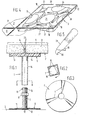
- Fig. 1 is a cross-sectional side view, partly with exploded parts, of a detail of the floor construction;
- Fig. 2 is a cross-sectional view on the Line II-II of Fig. 1;
- Fig. 3 is a top view of the base plate of the adjusting foot;
- Fig. 4 diagrammatically shows the interconnection of four floor tiles,and
- Fig. 5 shows a carpet knife that is particularly suitable for use in the floor construction according to the invention.
- As shown in the drawing, adjusting
feet 1 are used for supporting floor panels in the form oftiles 2 spaced above asubfloor 3..Each adjustingfoot 1 supports a plurality of tile angular points, use being made of a separation fitting 4, e.g. at four tile angular points one separation cross. - A
carpet 5 can be installed on the floating floor formed by thetiles 2 by means of an adhesive layer, not shown. - The adjusting
foot 1 is composed of abase plate 6, ascrewed spindle 7 with thereon anut 8 adjustable in height and defining the local level of the floating floor, as well as a platform 9 on which tileangular points 2 are supported. - The base plate comprises a
central dishing 10 with downwardly embossedportions 11 starting thereform and distributed circumferentially, having dephts increasing towards the edge of theplate 6 to such a value that in unloaded condition and placed on a flat bottom, the base plate rests exclusively on the embossedportions 11 and the under-side of thecentral dishing 10 is clear of the bottom. - At the under-side of the central dishing 10 of the base plate there is applied a two-sided
adhesive layer 12. - The tile carrier platform 9 comprises a
metal receptacle 13 with upright side edges, which is filled with anelastomer 14 as far as the top level of the edges. At the under-side of thereceptacle 13 there is provided abush 14 having a rectangular cross-section in the embodiment shown (see Fig. 2) dimensioned in such a manner that the shortest distance between opposite sides is approximately equal to the outside dimension of thescrewed spindle 7. In the screw thread of thespindle 7 there are disposedlocal deformations 16 that project beyond the screw thread. - The positioning of such an adjusting foot is effected as follows:
- At the appropriate place it has only to be ensured that the location where the central dishing is present is reasonably flat. The assembly of
base plate 6, screwedspindle 7 andbush 14 placed thereover with platform 9 is mounted at this location and fixed onto the under-side of the central dishing 10 by means of the two-sidedadhesive layer 12. The platform 9 with thebush 14 attached to the under-side thereof is pushed over the free top end of thescrewed spindle 7, i.e. with thebush 14 in the position shown in Fig. 2, in such a manner that theprojections 16 of thescrewed spindle 7 extend into the free angular zones of thebush section 14. After vertical adjustment of the platform by means of thenut 8, the platform is turned in the arrow direction shown in Fig. 2, so that theprojections 16 deform the walls of thebush section 14, thus fixing the platform 9 at the correct level. - After the positioning of a plurality of adjusting
feet 1 according to a grid pattern, thefloating floor tiles 2 are positioned by means of separation crosses 4 and as a result of their weight, thebase plate 6 of the adjustingfoot 1 is deformed in the sense that, while so far the weight of the adjusting foot had been taken up by the downwardly embossedzones 11, the weight of thetiles 2 comes to rest directly on thesubfloor 3 via thebush 14 and thescrewed spindle 7 via the dishing 10 and the two-sidedadhesive layer 12. - The
floor tiles 2 each comprise ametal receptacle 17 having abottom 18,upright walls 19 with acircumferential flange 20 at the upper edge of each. The receptacle is filled with compressionresistant material 21 such as concrete as far as the level of thecircumferential flange 20. - As shown in Fig. 1, the
tiles 2 are positioned by means of the separation fittings 4 in such a manner on the platforms 9 of the adjustingfeet 1 that a space is provided between facingedge flanges 20, however only along a limited distance, in the orderof 1-3 mm. This slight interspace between adjoining tiles enables to apply a continuous adhesive layer on a mounted floating floor for acontinuous carpet 5. - If for lifting a tile 2 - after the floor has been put into use - renewed access to the space between the floating floor and the
subfloor 3 is required, a tile lifting tool can be inserted in the space created at the angular points by theroundings 22. The space between adjoiningedge flanges 20 may serve for guiding a knife by means of which the carpet above the tile to be lifted can be cut. Preferably, use is made therefore of a knife shown in Fig. 5, which is fitted with ahandle 28, ablade 29 and aguide 30 attached to thehandle 28 and extending into the cutting plane. During the cutting movement of the knife, the guide ensures a separation between carpet piles, which consequently are not cut by the knife, so that during the subsequent replacement of a lifted tile, the carpet adhered thereto links up again entirely with surrounding carpet portions. - Preferably, the under-side of the
metal receptacle 17 of eachtile 2 has an arch shape, with arch legs at the angular points. To this effect, the deepest portions of the metal receptacle are present in theangular zones 23 and thereceptacle bottom 18 has a plurality df raised portions. Between two angular zones, the receptacle bottom is raised withportions 24 having substantially the configuration of one half of a truncated cone, by means of which the receptacle bottom between twoangular zones 23 links up with therespective receptacle sidewall 19. - In the middle of the
bottom 18 there is provided a raisedportion 25 having the shape of a sphere segment and from the central zone there extend radial, downwardly embossedzones 26 terminating in theangular zones 23. Theradial dishings 26 form on the one end guides for concrete poured in the middle of the receptacle to the recessedangular zones 23 and on the other end radial reinforcing ribs are formed in the concrete mass in thedished portions 26. - Furthermore, the
metal receptacle 17 is also fitted withdishings 27 extending between the central raisedportion 25 and thewall elevations 24, parallel to therespective receptacle walls 19, by means of which reinforcing ribs can also be formed in the concrete mass, the vertical dimensions of said ribs can be selected in such a manner that if only use is made of a part of a floating floor tile, e.g. along an edge of a floating floor, the respective tiles with a rib thus formed can rest in adishing 27 on an edge supporting molding of the room. - The floating floor construction according to the invention has a number of highly favourable properties when in use.As already observed, it is possible to apply a carpet or other fixed floor covering by means of a continuous adhesive layer in the same manner as on a continuous floot area not composed of tiles or such like panels.
- Due to the interspace of the tiles in horizontal direction, sound vibrations cannot be propagated directly from one tile to an adjoining tile. When a
tile 2 is loaded (see Fig. 1) themetal receptacle 13 of the adjustingfoot 1 will slightly deflect at its circumference, so that the load is taken over at least partly by theelastomer 14 in thereceptacle 13 and thus the floating floor is slightly resilient. - Since a
carpet 5 laid on the floating floor is in direct contact at the circumference of eachtile 2 with thecircumferential flange 20 of themetal tile receptacle 17 and since themetal receptacle 17 is in direct contact at each adjusting foot with themetal receptacle 13 of the platform 9 of the adjusting foot, static electricity is discharged immediately in all places. - In spite of the fact that the floating floor has sufficient structural strength, there are a great many places distributed over the entire floor where the thickness of the material of the
tiles 2 is slight, e.g. at the apex of each of thetruncated cone configurations 24. In such places a passage to the space underneath the floating floor can be made in a simple manner by using light material.
Claims (12)
1. An adjusting foot destined for use in a floating floor construction, comprising adjoining floor slabs supported at the angular points by adjusting feet by means of which the floating floor rests on the subfloor without attachment means, a screwed spindle with nut and a platform having at the under-side a bush fitting over the screwed spindle and resting on the nut, characterized in that the base plate is fitted with a central dishing for receiving the screwed spindle, while the plate portion around the central dishing is provided with radial, downwardly embossed zones having depths increasing towards the edge of the plate in such a manner that the adjusting foot, in unloaded conditions, rests on embossed zones and in loaded condition the supporting function is taken over by the under-side of the central dishing, which is provided with a two-sided adhesive layer.
2. An adjusting foot according to claim 1, characterized in that the bush of the tile supporting platform is provided in cross-section with flat sides with an interspace substantially equal to the outside dimension of the screwed spindle, which is enlarged at least at one location by deformation.
3. An adjusting foot according to claim 1 or 2, characterized in that the platform is formed by a metal receptacle filled as far as the upper edge with an elastomer.
4. An adjusting foot according to claim 3, characterized in that the metal receptacle contains a sheet of synthetic rubber filling the receptacle, having a Shore hardness of 60-80.
5. A floating floor construction with adjusting feet according to any one of the preceding claims, wherein use is made of a separation fitting, such as a cross to be placed on the platform, characterized in that the floor panels are kept interspaced by the separation fitting.
6. A floor panel for use in a floating floor construction in combination with adjusting feet according to any one of the preceding claims, characterized in that the floor panel is designed in the form of a tile consisting of a metal receptacle having a bottom and upright edges with a short, outwardly directed circumferential flange at the upper edge, said receptacle being filled as far as the upper edge with compression resistant material, in particular concrete.
7. A floating floor construction according to claim 5 and using a floor panel according to claim 6, characterized in that the dimensions of the separation cross and of the tile receptacle, in particular the edge flanges thereof, are chosen in such a manner that in a mounted floating floor construction, the edge flanges of adjoining tiles have a slight interspace, in the order of 1-3 mm.
8. A floor panel according to claim 6 in the application according to claim 7, characterized in that the edge flanges of the tile receptacles are rounded at the angular points.
9. An aid for cutting a tile from a carpet laid on a floating floor according to any one of the preceding claims, in the form of a carpet knife having a handle and a blade, characterized in that the knife is fitted with a guide attached to the handle and extending into the cutting plane at the cutting edge side of the knife.
10. A floor panel according to claim 6 in the form of a floor tile consisting of a metal receptacle with a compression resistant filling, while the under-side of the tile has an arch shape, with the arch legs at the angular points, characterized in that the metal receptacle has the maximum depth in the angular zones, outside the angular zones the receptacle depth decreases abruptly and the receptacle bottom, except for discontinuities, extends substantially horizontally at a level lying at about 1/3 of the receptacle depth, while halfway two angular zones the receptacle bottom with raised portions links up approximately with the configuration of one half of a truncated cone with the receptacle sidewall in question.
11. A floor panel according to claim 10, characterized in that in the central tile zone the horizontal bottom portion is discontinued by a raised portion having the shape of a sphere segment, while radially embossed zones of outwardly increasing depths extend according to the tile diagonals from adjacent the sphere segment into the angular zones.
12. A floor panel according to claim 10 or 11, charachterized by dishings disposed in the tile receptacle between the central sphere segment and each of the truncated cones, extending parallel to the respective tile edges, said dishings having such depths that, when cutting a tile for placement at an edge of a floor construction, the sub-tile with the rib formed by a dishing can rest on a molding or the like edge support.
Applications Claiming Priority (2)
| Application Number | Priority Date | Filing Date | Title |
|---|---|---|---|
| NL8301832A NL8301832A (en) | 1983-05-24 | 1983-05-24 | FLOATING FLOOR STRUCTURE. |
| NL8301832 | 1983-05-24 |
Publications (2)
| Publication Number | Publication Date |
|---|---|
| EP0138236A2 true EP0138236A2 (en) | 1985-04-24 |
| EP0138236A3 EP0138236A3 (en) | 1986-04-30 |
Family
ID=19841899
Family Applications (1)
| Application Number | Title | Priority Date | Filing Date |
|---|---|---|---|
| EP84200758A Withdrawn EP0138236A3 (en) | 1983-05-24 | 1984-05-24 | Sectional false floor |
Country Status (2)
| Country | Link |
|---|---|
| EP (1) | EP0138236A3 (en) |
| NL (1) | NL8301832A (en) |
Cited By (6)
| Publication number | Priority date | Publication date | Assignee | Title |
|---|---|---|---|---|
| FR2595105A1 (en) * | 1986-02-28 | 1987-09-04 | Vion Fabrice | Transportable sports ground, in particular tennis court |
| AU586962B1 (en) * | 1986-07-25 | 1989-07-27 | Chien-Teh Huang | Combined floor pedestal and floor outlet |
| DE4228601A1 (en) * | 1991-09-11 | 1993-04-01 | Taisei Electronic Ind Co | Construction method for raised floor - has floor panels supported on each corner by adjustable leg |
| US5363613A (en) * | 1992-03-12 | 1994-11-15 | Hendry Mechanical Works | Rigid supporting structures |
| ES2215492A1 (en) * | 2004-05-13 | 2004-10-01 | Juan Muñoz Molina | Adjustable acoustic damper for use in construction of e.g. floating concrete floor, has stabilizer formed by lugs, and upper front part provided with hole, which is formed in interior orifice, where orifice is screwed into base metal |
| BE1029124B1 (en) * | 2021-02-18 | 2022-09-12 | Solidor Bvba | FIRE-RESISTANT TERRACE BARRIER |
Citations (3)
| Publication number | Priority date | Publication date | Assignee | Title |
|---|---|---|---|---|
| FR2195744A1 (en) * | 1972-08-07 | 1974-03-08 | Tate Architectural Products | |
| FR2317445A1 (en) * | 1975-07-10 | 1977-02-04 | Cs Steel Et Cie Sa | Slab for construction of raised floor - is smooth upper panel with ribbed underlying caisson supported on jacks |
| LU82620A1 (en) * | 1980-07-14 | 1982-02-17 | Hiross Int Co Sa | BASE FOR THE CONSTRUCTION OF Raised floors |
-
1983
- 1983-05-24 NL NL8301832A patent/NL8301832A/en not_active Application Discontinuation
-
1984
- 1984-05-24 EP EP84200758A patent/EP0138236A3/en not_active Withdrawn
Patent Citations (3)
| Publication number | Priority date | Publication date | Assignee | Title |
|---|---|---|---|---|
| FR2195744A1 (en) * | 1972-08-07 | 1974-03-08 | Tate Architectural Products | |
| FR2317445A1 (en) * | 1975-07-10 | 1977-02-04 | Cs Steel Et Cie Sa | Slab for construction of raised floor - is smooth upper panel with ribbed underlying caisson supported on jacks |
| LU82620A1 (en) * | 1980-07-14 | 1982-02-17 | Hiross Int Co Sa | BASE FOR THE CONSTRUCTION OF Raised floors |
Cited By (7)
| Publication number | Priority date | Publication date | Assignee | Title |
|---|---|---|---|---|
| FR2595105A1 (en) * | 1986-02-28 | 1987-09-04 | Vion Fabrice | Transportable sports ground, in particular tennis court |
| AU586962B1 (en) * | 1986-07-25 | 1989-07-27 | Chien-Teh Huang | Combined floor pedestal and floor outlet |
| DE4228601A1 (en) * | 1991-09-11 | 1993-04-01 | Taisei Electronic Ind Co | Construction method for raised floor - has floor panels supported on each corner by adjustable leg |
| US5501754A (en) * | 1991-09-11 | 1996-03-26 | Taisei Electronic Industries Co., Ltd. | Method of assembling raised dry-floor |
| US5363613A (en) * | 1992-03-12 | 1994-11-15 | Hendry Mechanical Works | Rigid supporting structures |
| ES2215492A1 (en) * | 2004-05-13 | 2004-10-01 | Juan Muñoz Molina | Adjustable acoustic damper for use in construction of e.g. floating concrete floor, has stabilizer formed by lugs, and upper front part provided with hole, which is formed in interior orifice, where orifice is screwed into base metal |
| BE1029124B1 (en) * | 2021-02-18 | 2022-09-12 | Solidor Bvba | FIRE-RESISTANT TERRACE BARRIER |
Also Published As
| Publication number | Publication date |
|---|---|
| EP0138236A3 (en) | 1986-04-30 |
| NL8301832A (en) | 1984-12-17 |
Similar Documents
| Publication | Publication Date | Title |
|---|---|---|
| US4541132A (en) | Shower pan | |
| US4482592A (en) | Vibration isolation pad | |
| EP2203613B1 (en) | Air tight access floor assembly | |
| US20020121583A1 (en) | Pedestal support for an elevated paver deck assembly | |
| US4436274A (en) | Vibration dampening support | |
| JPH06307064A (en) | Floor panel supporting leg and double floor | |
| CZ20001559A3 (en) | Device for adjusting incline of structural surface on a plate for ensuring exact contact | |
| KR102217348B1 (en) | fanel for sound insulation | |
| EP0138236A2 (en) | Sectional false floor | |
| EP0289511B1 (en) | Access flooring system | |
| KR101971619B1 (en) | Installation for Construction of Deck Tiles | |
| GB2230653A (en) | Trunking for use in a raised floor | |
| EP3686371A1 (en) | A support for raised floor | |
| JP6764634B2 (en) | Floating floor structure system and load bearing device for floating floor structure | |
| EP0872204A2 (en) | Shower tray arrangement for disabled persons | |
| GB2188955A (en) | Base plates for pedestals of access type raised floor | |
| US5140791A (en) | Limited access feeder raceway | |
| GB2443693A (en) | Service Box | |
| EP1276940B1 (en) | Wet room floor surface or roof surface | |
| AU2006200759B1 (en) | Pedestal for access floor | |
| GB2150953A (en) | Manholes and catch-pits | |
| CA1197652A (en) | Shower pan and method of construction | |
| GB2227035A (en) | Floor panel | |
| JPH0510099Y2 (en) | ||
| JP2024052106A (en) | Floating floor structure and floating floor construction method |
Legal Events
| Date | Code | Title | Description |
|---|---|---|---|
| PUAI | Public reference made under article 153(3) epc to a published international application that has entered the european phase |
Free format text: ORIGINAL CODE: 0009012 |
|
| AK | Designated contracting states |
Designated state(s): AT BE CH DE FR GB IT LI LU NL SE |
|
| PUAL | Search report despatched |
Free format text: ORIGINAL CODE: 0009013 |
|
| AK | Designated contracting states |
Kind code of ref document: A3 Designated state(s): AT BE CH DE FR GB IT LI LU NL SE |
|
| STAA | Information on the status of an ep patent application or granted ep patent |
Free format text: STATUS: THE APPLICATION IS DEEMED TO BE WITHDRAWN |
|
| 18D | Application deemed to be withdrawn |
Effective date: 19861203 |