EP0138135B2 - Plant management system - Google Patents
Plant management system Download PDFInfo
- Publication number
- EP0138135B2 EP0138135B2 EP84111709A EP84111709A EP0138135B2 EP 0138135 B2 EP0138135 B2 EP 0138135B2 EP 84111709 A EP84111709 A EP 84111709A EP 84111709 A EP84111709 A EP 84111709A EP 0138135 B2 EP0138135 B2 EP 0138135B2
- Authority
- EP
- European Patent Office
- Prior art keywords
- module
- modules
- bus
- plant
- units
- Prior art date
- Legal status (The legal status is an assumption and is not a legal conclusion. Google has not performed a legal analysis and makes no representation as to the accuracy of the status listed.)
- Expired - Lifetime
Links
Images
Classifications
-
- G—PHYSICS
- G06—COMPUTING; CALCULATING OR COUNTING
- G06F—ELECTRIC DIGITAL DATA PROCESSING
- G06F11/00—Error detection; Error correction; Monitoring
- G06F11/07—Responding to the occurrence of a fault, e.g. fault tolerance
- G06F11/16—Error detection or correction of the data by redundancy in hardware
- G06F11/20—Error detection or correction of the data by redundancy in hardware using active fault-masking, e.g. by switching out faulty elements or by switching in spare elements
- G06F11/2002—Error detection or correction of the data by redundancy in hardware using active fault-masking, e.g. by switching out faulty elements or by switching in spare elements where interconnections or communication control functionality are redundant
- G06F11/2005—Error detection or correction of the data by redundancy in hardware using active fault-masking, e.g. by switching out faulty elements or by switching in spare elements where interconnections or communication control functionality are redundant using redundant communication controllers
-
- G—PHYSICS
- G06—COMPUTING; CALCULATING OR COUNTING
- G06F—ELECTRIC DIGITAL DATA PROCESSING
- G06F11/00—Error detection; Error correction; Monitoring
- G06F11/07—Responding to the occurrence of a fault, e.g. fault tolerance
- G06F11/16—Error detection or correction of the data by redundancy in hardware
- G06F11/20—Error detection or correction of the data by redundancy in hardware using active fault-masking, e.g. by switching out faulty elements or by switching in spare elements
- G06F11/2002—Error detection or correction of the data by redundancy in hardware using active fault-masking, e.g. by switching out faulty elements or by switching in spare elements where interconnections or communication control functionality are redundant
- G06F11/2007—Error detection or correction of the data by redundancy in hardware using active fault-masking, e.g. by switching out faulty elements or by switching in spare elements where interconnections or communication control functionality are redundant using redundant communication media
-
- G—PHYSICS
- G06—COMPUTING; CALCULATING OR COUNTING
- G06F—ELECTRIC DIGITAL DATA PROCESSING
- G06F11/00—Error detection; Error correction; Monitoring
- G06F11/07—Responding to the occurrence of a fault, e.g. fault tolerance
- G06F11/16—Error detection or correction of the data by redundancy in hardware
- G06F11/20—Error detection or correction of the data by redundancy in hardware using active fault-masking, e.g. by switching out faulty elements or by switching in spare elements
- G06F11/202—Error detection or correction of the data by redundancy in hardware using active fault-masking, e.g. by switching out faulty elements or by switching in spare elements where processing functionality is redundant
- G06F11/2038—Error detection or correction of the data by redundancy in hardware using active fault-masking, e.g. by switching out faulty elements or by switching in spare elements where processing functionality is redundant with a single idle spare processing component
-
- H—ELECTRICITY
- H04—ELECTRIC COMMUNICATION TECHNIQUE
- H04L—TRANSMISSION OF DIGITAL INFORMATION, e.g. TELEGRAPHIC COMMUNICATION
- H04L1/00—Arrangements for detecting or preventing errors in the information received
- H04L1/22—Arrangements for detecting or preventing errors in the information received using redundant apparatus to increase reliability
-
- H—ELECTRICITY
- H04—ELECTRIC COMMUNICATION TECHNIQUE
- H04L—TRANSMISSION OF DIGITAL INFORMATION, e.g. TELEGRAPHIC COMMUNICATION
- H04L12/00—Data switching networks
- H04L12/28—Data switching networks characterised by path configuration, e.g. LAN [Local Area Networks] or WAN [Wide Area Networks]
- H04L12/40—Bus networks
- H04L12/407—Bus networks with decentralised control
- H04L12/417—Bus networks with decentralised control with deterministic access, e.g. token passing
-
- Y—GENERAL TAGGING OF NEW TECHNOLOGICAL DEVELOPMENTS; GENERAL TAGGING OF CROSS-SECTIONAL TECHNOLOGIES SPANNING OVER SEVERAL SECTIONS OF THE IPC; TECHNICAL SUBJECTS COVERED BY FORMER USPC CROSS-REFERENCE ART COLLECTIONS [XRACs] AND DIGESTS
- Y02—TECHNOLOGIES OR APPLICATIONS FOR MITIGATION OR ADAPTATION AGAINST CLIMATE CHANGE
- Y02P—CLIMATE CHANGE MITIGATION TECHNOLOGIES IN THE PRODUCTION OR PROCESSING OF GOODS
- Y02P90/00—Enabling technologies with a potential contribution to greenhouse gas [GHG] emissions mitigation
- Y02P90/02—Total factory control, e.g. smart factories, flexible manufacturing systems [FMS] or integrated manufacturing systems [IMS]
Definitions
- This invention is in the field of distributed digital process control systems and, more particularly, relates to a plantwide system for monitoring and controlling industrial and electric utility plants, including intersystem communications and related plant management functions for plants ranging from modest to very large.
- Digital process control and data acquisition systems such as that identified as the TDC 2000 process control system manufactured and sold by Honeywell Inc., for example, include a comprehensive set of algorithms and auxiliaries to control and monitor various manufacturing processes or the operation of utilities.
- the TDC 2000 Control System can be tailored to satisfy a wide range of process requirements at the loop or unit level.
- the TDC 2000 system includes standardized units that are linked together by a data highway and each of the major units of such a system includes a microprocessor with its own firmware and data base to provide a distributed control system.
- Such distributed digital data acquisition and control systems to date have been essentially limited to controlling part of the processes conducted in petroleum refineries, for example, such as catalytic crackers, or in an electric utility plant the operation of boilers, generators, nuclear reactors, etc.
- US-A-42 96 464 describes a process control system with local microprocessor control units, wherein such unit by means of a multi-conductor parallel transmission bus is connected to a central processor unit.
- the control unit comprises an internal bit serial highway which by means of a communication bus interface controller communicates with said multi-conductor bus.
- Connected to said internal unit bus are different types of process interface units and an operator station as well as a highway traffic director controlling the communication on said internal control unit bus.
- Each control unit comprises a microprocessor, a programmable read-only memory and a random access memory as well as a process input/output controller and an A/D converter.
- the microprocessor bus connecting those parts of the control unit together communicates with the internal control unit bus via a data highway interface control unit.
- a plant management system is for a high-performance universal operator station at which one or more operators can supervise and control the processes being executed by the plant, or the total operation of a large plant from raw material input to finished goods output.
- Such a system must also be reliable, fault tolerant, and preferably be sufficiently modular so that additional functions can be added as needed to tailor a plant management system to meet the specific requirements of any given manufacturing complex at a minimum of cost while at the same time providing a highly reliable system which can be readily modified to meet changing requirements placed on such a complex.
- an object of the invention to provide a plant management system that is capable of providing plant-wide control and data acquisition functions by communicating directly and on a real-time basis with one or more process control subsystems of the system, and in which relevant data needed for the efficient operation of the total plant is available to all data-processing resources of the system.
- the invention should provide a plantwide system in which additional functional capability can be provided incrementally and existing capabilities can also be increased incrementally.
- the Siemens TELEPERM M microprocessor-based automation system as described in ,,Siemens Energytechnik", 6/79, 11/79, 9/80, 2/83 and in Siemens Catalogue MP29 "Prozeßleitsystem TELEPERM M" includes the features described in the preamble of claim 1.
- the present invention utilizes the characterizing features of claim 1. Further preferred features and embodiments are disclosed in the subsequent claims.
- the invention provides a highly reliable plant management system which includes a token-passing local control network consisting of a plurality of different types of physical modules, at least one module of each type being designated as a primary module with some or all primary modules having one or more backup modules, which backup modules take over the performance of their primary module if its primary fails.
- a plant management system includes one or more digital process control and data acquisition subsystems and a plant control network.
- Each control subsystem includes a data highway, and process control, and process interface units.
- the plant control network is a token-passing distributed plant control network in which a plurality of physical modules communicate with one another over a plant control bus.
- One type of physical module provides data communication and translation facilities between the plant control network bus and the data highway of a control subsystem.
- Another type of module provides a universal operator station at which is available all information and capabilities needed by an operator to operate a plant.
- the present invention provides a computerized plant management system, a token-passing network of up to "m" electronic modules of "p" types.
- Each such physical module when connected to the common communication medium, or bus, of the network has the capability of transmitting binary data, or information, to other physical modules of the network and of receiving information from them.
- Each of the physical modules of the network is the equal, or the peer, of the others, and each is assigned a different n bit physical network address. Whichever physical module "has the token” at any given instant of time has the sole right to transmit signals over the network bus and to transmit a token to its successor module.
- Each of the physical modules includes a basic interface unit (BIU), a transceiver, a module bus, a module central processor unit and a module memory. Additional units, or devices, to provide a module with additional functional capabilities required by a module of a given type communicate with the other units of each module over the module's bus.
- BIU basic interface unit
- Additional units, or devices, to provide a module with additional functional capabilities required by a module of a given type communicate with the other units of each module over the module's bus.
- One type of physical module of the plant control network is a universal operator station module which provides the means by which the operator responsible for the overall operation of the plant being supervised obtains the information needed to perform this function. To do this, the universal operator station has the capability of transmitting information, or commands, to control subsystems of the plant management system to provide the highest level of control over the processes being supervised.
- All communications between a universal operator module and other modules of the network are via the network's communication media, or plant control bus, which provides the universal operator station module with access to the data highways of any digital process control and data acquisition subsystems of the plant management system and over such data highways access to the units of each control subsystem of the plant management system.
- a gateway module provides other modules of the plant control network access to data available at the units of a process control and data acquisition subsystem as needed.
- a history module includes a mass-memory storage device, or a mass data storage device, such as a disc digital data storage unit.
- the disc storage unit of a history module permits nonvolatile data storage and retrieval of large volumes of binary data. Types of data stored by such a unit would be trend histories, displays, and to provide backup storage for programs for the units of the control subsystems of the plant management system, for example.
- an application module provides additional general-purpose data-processing capabilities which are particularly useful in conjunction with, or in support of, the process control subsystems.
- application modules are used to acquire additional data, to produce new or modified process control algorithms, to collect information concerning batch processes, as well as to provide additional computational facilities relative to the optimization of plant processes being supervised.
- Still another type of physical module provides for the real-time exchange of information between modules of the plant control network of the plant management system and a medium- or large-scale, general-purpose data-processing system.
- functions of such general-purpose computers provide, in a plant environment, supervisory optimization, generalized program preparation, and execution facilities for programs written in high-level program languages.
- Additional types of modules permit communication between one plant control network of the present invention and another such network, if desired.
- the plant control system of this invention consists of a number of electronic modules which communicate with one another over a high-speed bit serial plant control bus.
- Each of the modules includes a module CPU and a module memory with additional controllers and devices being added to provide the desired functionality or functionalities required of a given type of physical module, such as that of a universal operator station module, etc.
- This architecture creates a distributed processing environment which provides for improved reliability and performance over centralized systems. Reliability is improved because, if one module of the system fails, the others will remain operational and the system as a whole is not disabled as would be the case with the failure of a centralized system.
- Performance is improved and faster response times are obtained as a result of the increased computer processing resources available in each physical module, as well as a result of the concurrency and parallelism in processing data provided by these resources.
- Reliability is improved by redundancy of physical modules of the plant control network of the system to the extent necessary to achieve desired system availability.
- Any network module of a given type may have one or more standby, or backup, modules of the same type, which backup modules maintain data synchrony, but not operational synchronism with their associated primary module.
- a standby secondary, or backup, module takes over performance of the functions of its primary module should the primary module fail. This type of redundancy provides a level of fault tolerance which can be incrementally increased to a desired level.
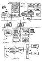
- FIG. 1 is a schematic block diagram of the plant management system of this invention.
- Figure 2 is a schematic block diagram illustrating the common elements of each physical module of the plant control network of the system.
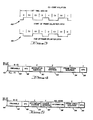
- Figure 3 illustrates the wave forms of start-of-frame and end-of-frame delimiters.
- Figure 4 is the format of a token-passing frame.
- Figure 5 is the format of an information frame.
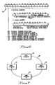
- Figure 6 defines the significance of various bit configurations of a destination address field of a frame.
- Figure 7 illustrates a logical ring formed by the modules of the plant control network of the system.
- FIG. 1 The organization, or architecture, of plant management system 10 is illustrated in Figure 1.
- the elements above dashed line 12 of Figure 1 form, or constitute, plant control network 14, a token-passing distributed local-area network.
- Physical modules 16 of network 14 are of various specialized functional types, as will be described below. Each physical module 16 is the peer, or equivalent, of others in terms of right of access to the network's communication medium, or plant control bus, 18, for the purpose of transmitting data to other modules 16 of network 14.
- Highway gateway module 16-HG-1 provides communications and data translation facilities between plant control bus 18 and data highway 20-1 of distributed digital process control and data acquisition subsystems 22-1, as illustrated in Figure 1.
- Highway gateway module 16-HG-2 is a backup, or standby, module for its primary module 16-HG-1 and takes over its functions if module 16-HG-1 should fail.
- Highway gateway module 16-HG-3 provides communications and data translation facilities between plant control bus 18 and the data highway of control subsystem 22-2.
- Module 16-HG-3 is a primary module backed up by its secondary, or backup, module 16-HG-4.
- Each of the process control subsystems 22-1 and 22-2 is, in the preferred embodiment, a Honeywell Inc. TDC 2000 Process Control System, a description of which is found in the publication entitled "Basic System TDC 2000 System Summary", published 6/81 under No. SY-02-02 by Honeywell Inc.
- Control subsystem 22-1 may include units, in addition to data highway 20-1, such as a highway traffic director 24-1, an operator station 26-1, several different types of controllers 28-1, such as basic, multifunction, or extended controllers, and process interface units (PlU's) 30-1. Details of control subsystem 22-2 are not illustrated since they are substantially similar to those of subsystem 22-1.
- the data highway 20 in each control subsystem 22 is a dual redundant bus consisting of two separate coaxial cables.
- a highway traffic director 24 monitors and coordinates all communication traffic between data highway units, or devices; i.e., PlU's 30, controllers 28, operator station 26, etc. Controllers 28 have the functional capabilities of several conventional single-loop process controllers plus enhanced functionality.
- Multifunction, or batch, controller 28 is designed to control noncontinous, or batch-type processes.
- Operator station 26 provides an interface between the process operator and the process being controlled by a control subsystem 22, for example.
- Process interface units 30 scan each input point to which they are connected, to measure temperature, pressure, flow rates, etc., to digitize this information, and make such information available to other devices of its subsystem 22 on demand.
- Process interface units 30 scan each input point to which they are connected, to measure temperature, pressure, flow rates, etc., to digitize this information, and make such information available to other devices of its subsystem 22 on demand.
- Universal operator station module 16-US-1 of network 14 is the work station for one or more plant operators. It includes an operator console which is the interface between the plant operator, or operators, and the process or processes of the plant for which they are responsible.
- Each universal operator station module, such as 16-US-1, and its backup modules 16-US-2 and 16-US-3, for example, is connected to plant control bus 18, and all communications between the primary universal operator station module, such as 16-US-1, and any other module 16 of network 14, including its backup modules 16-US-2 and 16-US-3, is by means of plant control bus 18.
- Universal operator station module 16-US-1 has access to data that is on control bus 18 and the resources and data available through, or from, any of the other modules 16 of network 14.
- Each universal station module 16-US includes a cathode ray tube display, designated CRT, which includes a video display generator; an operator keyboard, a floppy disc data storage device, trend pen recorders, and status displays, for example.
- Each module 16-HM includes at least one conventional disc mass-storage device such as a Winchester disc, which disc storage device provides a large-volume of nonvolatile, nonremovable storage capability for binary data.
- the types of data stored by such a mass-storage device are typically trend histories, or data from which such trends can be determined, data that constitutes, or forms, CRT-type displays, copies of programs for the units of the control subsystems 22, for modules 16, or for units of the modules 16 of plant control network 14.
- a disc data storage unit of a history module such as 16-HM-1 can store up to 32.5 megabytes of data.
- An application module 16-AM-1 Another type of module that can be incorporated into the network 14 is an application module 16-AM-1.
- the backup module for primary module 16-AM-1 is designated in Figure 1 as 16-AM-2.
- Primary application module 16-AM-1 provides additional data-processing capability in support of the process control functions performed by the controllers 28 of process control subsystems 22-1 and 22-2 of plant management system 10, such as data acquisition, alarming, batch history collection, and provide continous control computational facilities when needed.
- the data processing capability of an applicaton module 16-AM is provided by its module processor and module memory.
- Computer module 16-CM-1 uses the standard or common units of all physical modules to permit a medium-to-large scale, general-purpose data-processing system to communicate with other modules 16 of network 14 and the units of such modules over bus 18 and the units of control subsystems 22 via a highway gateway module 16-HG.
- Data-processing systems of a computer module 16-CM-1 are used to provide supervisory, optimization, generalized user program preparation and execution of such programs in higher-level program languages.
- the data-processing systems of a computer module 16-CM-1 have the capability of communicating with other such systems by a communication processor and communication lines, as is well known in the art. While a backup computer module could be provided, the cost of providing one compared with benefits of doing so weigh against doing so at this time.
- Plant control bus 18 is a high-speed, bit serial dual redundant communication bus that interconnects all the modules 16 of plant control network 14.
- Bus 18 provides the only data transfer path between the principal sources of data, such as primary highway gateway modules 16-HG-1 and 16-HG-3, primary application module 16-AM-1, and primary history module 16-HM-1; and principal users of such data, such as primary universal operator station module 16-US-1, computer module 16-CM-1, and application module 16-AM-1.
- Bus 18 also provides the communication medium over which large blocks of data, such as memory images, can be moved from one module 16, such as history module 16-HM-1 to universal station module 16-US-1.
- Bus 18 is dual redundant in that it consists of two coaxial cables 18-1 and 18-2 that permit the serial transmission of binary signals over both at a rate of five megabits per second.
- the length of coaxial cables 18-1 and 18-2 is limited to 300 meters in the preferred embodiment.
- the maximum number of modules 16, including primary and backup modules 16 that may theoretically be connected to bus 18 is limited to 128, which, in binary notation, is 2 7 ; however, for reasons to be explained later, the number of modules that may be connected to a control bus 18 is limited to 64, or 2 6 .
- Each of the physical modules 16 includes certain, or required, standard units, which are illustrated in Figure 2.
- Each module 16 has a module bus interface unit, BIU, 32 which is connected to the two coaxial cables 18-1 and 18-2 of plant control bus 18 by a pair of transceivers 34-1 and 34-2. Additional details of module BIU 32 are illustrated and described in EP application 84 111 708.9 EP-A-0 137 437 entitled “Method for Initializing a Token-Passing Local-Area Network" and EP application 84 111 710.4 EP-A-0 137 438 entitled "Method for Passing a Token in a Local-Area Network".
- Each module 16 is also provided with a module bus 36 which, in the preferred embodiment, is capable of transmitting 16 bits of data in parallel, a module CPU 38 and a module memory 40.
- Other units to tailor each type of module 16 to satisfy its functional requirements are operatively connected to module bus 36 so that each such unit can communicate with the other units of a module 16 via its module bus 36.
- the BIU 32 of the module 16 that has the token at any given time is enabled to transmit data on, or over, bus 18. In the preferred embodiment, all transmissions by a BIU 32 are transmitted simulataneously, or in parallel, over coaxial cables 18-1 and 18-2.
- a BIU 32 of a module 16 when receiving information transmitted by another module 16 over coaxial cables 18-1 and 18-2, enables only one of its two transceivers 34 to transmit received binary signals to its associated BIU 32.
- Which transceiver 34-1 or 34-2 is enabled at any given time to receive signals from cables 18-1 or 18-2 is determined by the module's CPU 38 or by its BIU 32, depending on the circumstances; namely, how each is programmed to function, as is well known in the art.
- each BIU 32 has two receive channels, which are not illustrated, with each receive channel including a string of receive buffer registers.
- Each BIU 32 can be programmed so that all short frames of information go to one such receive channel while all long frames go to the other receive channel. Alternatively, all high-priority frames can be sent to one receive channel, while all low-priority frames go to the other.
- Network 14 utilizes the method for initializing a local-area token-passing network described and claimed in the cross-referenced application entitled "Method for Initializing a Token-Passing Local-Area Network” and the token-passing algorithm described and claimed in the cross-referenced application entitled “Method for Passing a Token in a Local-Area Network”.
- Each physical module 16 connected to bus 18 is assigned a unique physical address, a 7-bit address in the preferred embodiment. As stated above, a maximum of only sixty-four physical modules 16 are connected to control bus 18. A reason for this is that when two plant control buses 18 are connected by a gateway module, a single network is formed in which each module has a unique physical address. This permits the modules 16 of two plant control networks 14 to directly communicate with one another and to form a single logical ring from the modules 16 thereof.
- a token-passing frame, or token, 42 such as is illustrated in Figure 4, and an information frame 44 as illustrated in Figure 5.
- a token-pass frame 42 includes from 8 to 10 bytes of a preamble 46.
- Preamble 46 consists of signals of the same type, such as logical ones.
- Preamble 46 is followed by a start-of-frame delimiter, SFD 48, of one byte, destination address field 50 of two bytes, a source address field 52 of two bytes, a frame check sequence 54 of two bytes, which sequence is used to detect errors in frame 42, and an end-of-frame delimiter, EFD 56, of one byte.
- SFD 48 start-of-frame delimiter
- EFD 56 end-of-frame delimiter
- the information transmitted by the BIU 32 of each module 16 consists of binary signals which are Manchester encoded so that a receive clock can be derived from the signals as received by each receiving BIU.
- a logical zero is transmitted by the signal voltage level being low initially, or during the first half of the bit cell, and being high during the second half of the bit cell, a mid-bit low-to-high transition.
- a logical one is transmitted by the signal voltage level initially during the first half of the bit cell being high and being low during the second half, a mid-bit high-to-low transition.
- Manchester encoding requires that there always be a transition in the middle of each bit cell. If there is no such transition, a code violation, CV, occurs.
- Both start- and end-of-frame delimiters 48, 56 include code violations, four CV's each. By using CV's in this manner, a 4-bit error would have to occur to change valid data into a frame delimiter.
- An end-of-frame delimiter 56 is used rather than silence on bus 18 to avoid the possibility that reflections of signals on bus 18 would be interpreted as a transmission, after transmission by the BIU 32 having the token 42 at any given time, for example, has stopped.
- An antijabber timer of each BIU 32 inhibits the continuous transmission of signals by a BIU for more than a predetermined period of time, which period is substantially longer than is required to transmit the largest information frame 44. The timer is reset each time a BIU stops transmitting.
- an information frame 44 differs from that of a token-pass frame 42 only by including an information field 58.
- field 58 is limited to include between 100 and 4,088 bytes of binary data. All other fields of an information frame 44 are the same as that of token-pass frame 42.
- a frame is defined as packet of a message formatted for transmission over plant control bus 18.
- addresses there are two basic types of addresses: a physical address and a logical address.
- a physical address is the address of a given physical module 16, and field 50 is identified or decoded as being that of a physical module 16 when the most significant bit, bit position 15 of field 50, is a logical zero.
- Each module 16 has a unique 7-bit physical address.
- the physical address of a physical module 16 is determined by a multi-bit switch or by a series of mechanically-made circuit interconnections, or the like, mounted, in the preferred embodiment, on the printed circuit board of the module containing one of its transceivers 34.
- a token-pass frame 42 is identified by the three most significant bit positions, bits 15, 14, and 13 being logical zeros.
- the lower order seven-bit positions, bit positions 06-00, are the physical address of the physical module 16 to which a token 42, for example, is addressed.
- bit positions 15 and 14 are logical zeros and bit position 13 is a logical one, then the frame is a diagnostic frame addressed to the module 16 whose physical address corresponds to that of, or equals that defined by, the bits in the lower order seven bit positions of field 50.
- a diagnostic frame is a form of an information frame 44 and can be used to determine if a given problem or set of problems exist in the addressed module. If bits 15 and 14 are logical ones, then bit 13 designates which of the two receive channels of the addressed module's BIU 32 is to accept and process the frame. If bit 12 is set and the address is a physical address but not a token or a diagnostic frame, the frame is to be received, or is addressed to all physical modules 16 of network 14.
- a logical one in bit position 15 indicates that the address defined by the bits of the lower order bit positions, 12 through 00, is that of a logical entity or logical module where a logical entity or module is a program module or set of data. If bit 14 is a zero under such circumstances, then bit 13 designates which receive channel of the addressed BIU is to receive, or process, the frame. If bits 15 and 14 are both logical ones, then the frame is an interrupt, a high-priority message, and bit 13 designates the receive channel of the BIU to receive the interrupt.
- a BIU 32 determines if it is to accept an information frame with a logical address by means of a logical address filter table. The lower order 9 bits of the address field are the address of two bytes of data, a filter word, which is stored at each addressable location in the filter memory of each BIU. The higher order 4 bits of the logical address, bit positions 12-09, specify a bit position of the addressed filter word. If that bit is a logical one, then that frame is accepted by the module since it is addressed to a logical module or program stored in that module's memory 40.
- Each type of module 16 is comprised of hardware devices which are physically packaged together and designed to support a particular set of functions.
- the unit of redundancy in the network 14 is the physical module 16.
- a redundant, secondary, or backup, module 16 must be of the same type as its primary module so that both will have the same complement of hardware units.
- Each type of module 16 of network 14 is capable of having one or more backups.
- Each of modules 16 includes a module central processor unit 38 and a module memory 40, a random-access memory, and such additional controller devices, or units, which are configured to provide the desired functionality of that type of module; i.e., that of the operator station 16-US, for example.
- the data-processing capabilities of each module's CPU 38 and module memory 40 create a distributed processing environment which provides for improved reliability and performance of network 14 and plant management system 10.
- the reliability of network 14 and plant management system 10 is improved because, if one module 16 of network 14 fails, the other modules 16 will remain operational. As a result, network 14 as a whole is not disabled by such an occurrence as would be the case in centralized systems. Performance is improved by this distributed environment in that throughput and fast operator response times result from the increased computer processing resources, and the concurrency and parallelism of the data-processing capabilities of the system.
- Network 14 uses redundancy at the module 16 level to achieve the required system availability.
- Each physical module 16 of a given type may have one or more standby modules which maintain data synchrony, but not operational synchronism with the primary module.
- the secondary module takes over the operations or functions of its primary when the primary module with which it is associated fails.
- the existence of one or more redundant backup modules for each primary module is invisible to all applications which interface with the primary module.
- the primary module is the only one that is aware of the existence of its own backup units. Where the requirements to manage a plant require it, network 14 can have more than one primary module of each type. The only limitation is that the total number of primary and secondary modules of all types connected to bus 18 not exceed a predetermined maximum, 64 in the preferred embodiment.
- Each module 16 is responsible for the integrity of its own operation. The failure of a module 16 is detected by the module itself and, if it does detect such a failure, it will cease operation and send a terminating state, or status, message. Under certain circumstances, a module's bus interface unit 32 will send out a failed status message if its antijabber timer times out, for example. If a module, as a whole, is unable to send out a failed state or status message, its backup module will detect the failure of its primary because of the absence of periodic status messages which are transmitted by a primary module to its backup modules. A backup, or secondary, module 16, upon receipt of a terminating or failed status message, or, upon the absence of the receipt of its associated primary module's status message, starts operating as a primary module.
- each physical module The functions performed by each physical module are controlled by its programming, and each program entity, or program module, is assigned a logical address which is sometimes referred to as a logical module.
- the redundant, or backup, physical modules will contain the same set of logical functions or logical modules as their primary. It should be noted that the backup modules for a primary physical module of one type must be of the same type as its primary.
- Network 14 is initialized, as described in the cross-referenced application entitled “Method for Initializing a Token-Passing Local-Area Network", and, after the logical ring 60, as illustrated in Figure 7, consisting of the existing properly functioning physical modules 16 is initialized, the method by which a token 42 is passed between the predecessor and successor modules 16 is described in the cross-referenced application entitled “Method for Passing a Token in a Local-Area Network”.
- Each physical module 16, as it accepts a token does so by transmitting, within a predetermined period of time after receiving a token 42 addressed to it, an information frame 44 if available and then a token 42 addressed to its successor, physical module 16.
- An information frame 44 can supply information, can request information, or can issue instructions to one or more physical modules 16 or logical modules. To simplify network 14, each module 16 is limited to transmitting one information frame 42 each time it receives a token 44 addressed to it, or while it has the token.
- each module 16 One of the functions that each module 16 must perform that receives a frame other than a token frame 42 is to transmit to the physical module 16 that originated or transmitted the frame the fact that the addressed module has received the frame addressed to it.
- Backup modules are not programmed to accept logically addressed information frames addressed to their primary module. Periodically, such as once each half-second, each primary module will update its backup modules so that the backup modules will be in condition to assume the functions of its primary with a minimum of delay. The failure of a primary module to update its secondary module, or modules, within an allotted period of time, will cause its secondary, or one of its secondary physical modules, to become the primary and perform the functions of its primary physical module. This is done by changing the contents of the decoding key of the secondary module to that corresponding to its primary.
- a universal operator station module 16-US of network 14 provides a single window to the entire plant process; i.e., it provides access to all the data of system 10 and presents whatever data is required in forms best suited for the operator's understanding, such as alarm patterns, trends, which are pictorially depicted, as well as printed and annunciated messages or warnings, where appropriate, at one place and with a minimum of delay.
- System 10 can be tailored to the requirements of a given plant and can be readily expanded, or modified, as a given plant expands, or changes, without a major reconfiguration of system 10. This is achieved by using a limited number of types of physical modules 16 which communicate with one another over the plant control bus.
Description
- This invention is in the field of distributed digital process control systems and, more particularly, relates to a plantwide system for monitoring and controlling industrial and electric utility plants, including intersystem communications and related plant management functions for plants ranging from modest to very large.
- Digital process control and data acquisition systems such as that identified as the TDC 2000 process control system manufactured and sold by Honeywell Inc., for example, include a comprehensive set of algorithms and auxiliaries to control and monitor various manufacturing processes or the operation of utilities. The TDC 2000 Control System can be tailored to satisfy a wide range of process requirements at the loop or unit level. The TDC 2000 system includes standardized units that are linked together by a data highway and each of the major units of such a system includes a microprocessor with its own firmware and data base to provide a distributed control system. Such distributed digital data acquisition and control systems to date have been essentially limited to controlling part of the processes conducted in petroleum refineries, for example, such as catalytic crackers, or in an electric utility plant the operation of boilers, generators, nuclear reactors, etc.
- There is a need for a wider span, or degree, of control to permit plant-wide control of all the processes conducted by a given facility to improve efficiency and the products produced by large, complex industrial and utility facilities. Typically, attempts to do this, as shown in US-A 42 96 464, have required large general-purpose, or large specialized, digital data-processing systems to provide a greater degree of control and information gathering capability over one or more control systems, such as that provided by the TDC 2000 Control System, hereinafter sometimes referred to as a process control subsystem, that do the actual controlling of processes or portions of processes performed. US-A-42 96 464 describes a process control system with local microprocessor control units, wherein such unit by means of a multi-conductor parallel transmission bus is connected to a central processor unit. The control unit comprises an internal bit serial highway which by means of a communication bus interface controller communicates with said multi-conductor bus. Connected to said internal unit bus are different types of process interface units and an operator station as well as a highway traffic director controlling the communication on said internal control unit bus. Each control unit comprises a microprocessor, a programmable read-only memory and a random access memory as well as a process input/output controller and an A/D converter. The microprocessor bus connecting those parts of the control unit together communicates with the internal control unit bus via a data highway interface control unit. Connected to the process I/O controller are different input/output devices which can be analog or digital I/O boards. Typically, the analysis and special management functions needed to optimize processes, throughput, quality, to control inventory, etc., have been performed by data-processing systems that do not communicate directly, on a real-time basis, with process control subsystems as defined above. Thus, there exists a need for a higher level plant management system that can gather data on the operation of a total plant by continuously monitoring the performance of the various process control subsystems of the plant to provide plantwide control on a real-time basis.
- One of the requirements of such a plant management system is for a high-performance universal operator station at which one or more operators can supervise and control the processes being executed by the plant, or the total operation of a large plant from raw material input to finished goods output. Such a system must also be reliable, fault tolerant, and preferably be sufficiently modular so that additional functions can be added as needed to tailor a plant management system to meet the specific requirements of any given manufacturing complex at a minimum of cost while at the same time providing a highly reliable system which can be readily modified to meet changing requirements placed on such a complex.
- It is, therefore, an object of the invention to provide a plant management system that is capable of providing plant-wide control and data acquisition functions by communicating directly and on a real-time basis with one or more process control subsystems of the system, and in which relevant data needed for the efficient operation of the total plant is available to all data-processing resources of the system.
- Furthermore, the invention should provide a plantwide system in which additional functional capability can be provided incrementally and existing capabilities can also be increased incrementally. The Siemens TELEPERM M microprocessor-based automation system as described in ,,Siemens Energietechnik", 6/79, 11/79, 9/80, 2/83 and in Siemens Catalogue MP29 "Prozeßleitsystem TELEPERM M" includes the features described in the preamble of
claim 1. For achieving the objects described above, the present invention utilizes the characterizing features ofclaim 1. Further preferred features and embodiments are disclosed in the subsequent claims. The invention provides a highly reliable plant management system which includes a token-passing local control network consisting of a plurality of different types of physical modules, at least one module of each type being designated as a primary module with some or all primary modules having one or more backup modules, which backup modules take over the performance of their primary module if its primary fails. Summarizing the invention with other words a plant management system includes one or more digital process control and data acquisition subsystems and a plant control network. Each control subsystem includes a data highway, and process control, and process interface units. The plant control network is a token-passing distributed plant control network in which a plurality of physical modules communicate with one another over a plant control bus. While there are a limited number of different types with each type having different functions, all physical modules have common units, one of which is a module central processor unit. Both the number of modules and the number of types of modules of a plant control network have both a maximum and a minimum. Reliability of the plant management system is improved by a provision for redundancy at the physical module level. One type of physical module provides data communication and translation facilities between the plant control network bus and the data highway of a control subsystem. Another type of module provides a universal operator station at which is available all information and capabilities needed by an operator to operate a plant. - The present invention provides a computerized plant management system, a token-passing network of up to "m" electronic modules of "p" types. Each such physical module when connected to the common communication medium, or bus, of the network has the capability of transmitting binary data, or information, to other physical modules of the network and of receiving information from them. Each of the physical modules of the network is the equal, or the peer, of the others, and each is assigned a different n bit physical network address. Whichever physical module "has the token" at any given instant of time has the sole right to transmit signals over the network bus and to transmit a token to its successor module.
- Each of the physical modules includes a basic interface unit (BIU), a transceiver, a module bus, a module central processor unit and a module memory. Additional units, or devices, to provide a module with additional functional capabilities required by a module of a given type communicate with the other units of each module over the module's bus. One type of physical module of the plant control network is a universal operator station module which provides the means by which the operator responsible for the overall operation of the plant being supervised obtains the information needed to perform this function. To do this, the universal operator station has the capability of transmitting information, or commands, to control subsystems of the plant management system to provide the highest level of control over the processes being supervised. All communications between a universal operator module and other modules of the network are via the network's communication media, or plant control bus, which provides the universal operator station module with access to the data highways of any digital process control and data acquisition subsystems of the plant management system and over such data highways access to the units of each control subsystem of the plant management system.
- There are several standardized types of physical modules that are used in forming the plant control network of a plant management system. One such type of module is a highway gateway module, the function of which is to provide data communication and translation facilities between the plant control bus of the network and the data highway of a digital process control and data acquisition subsystem. A gateway module thus provides other modules of the plant control network access to data available at the units of a process control and data acquisition subsystem as needed.
- Another type of physical module of the plant control network, named a history module, includes a mass-memory storage device, or a mass data storage device, such as a disc digital data storage unit. The disc storage unit of a history module permits nonvolatile data storage and retrieval of large volumes of binary data. Types of data stored by such a unit would be trend histories, displays, and to provide backup storage for programs for the units of the control subsystems of the plant management system, for example.
- Yet another type of physical module of the plant network, an application module, provides additional general-purpose data-processing capabilities which are particularly useful in conjunction with, or in support of, the process control subsystems. Typically, application modules are used to acquire additional data, to produce new or modified process control algorithms, to collect information concerning batch processes, as well as to provide additional computational facilities relative to the optimization of plant processes being supervised.
- Still another type of physical module, a computer module, provides for the real-time exchange of information between modules of the plant control network of the plant management system and a medium- or large-scale, general-purpose data-processing system. Typically, functions of such general-purpose computers provide, in a plant environment, supervisory optimization, generalized program preparation, and execution facilities for programs written in high-level program languages. Additional types of modules permit communication between one plant control network of the present invention and another such network, if desired.
- The plant control system of this invention consists of a number of electronic modules which communicate with one another over a high-speed bit serial plant control bus. Each of the modules includes a module CPU and a module memory with additional controllers and devices being added to provide the desired functionality or functionalities required of a given type of physical module, such as that of a universal operator station module, etc. This architecture creates a distributed processing environment which provides for improved reliability and performance over centralized systems. Reliability is improved because, if one module of the system fails, the others will remain operational and the system as a whole is not disabled as would be the case with the failure of a centralized system. Performance is improved and faster response times are obtained as a result of the increased computer processing resources available in each physical module, as well as a result of the concurrency and parallelism in processing data provided by these resources. Reliability is improved by redundancy of physical modules of the plant control network of the system to the extent necessary to achieve desired system availability. Any network module of a given type may have one or more standby, or backup, modules of the same type, which backup modules maintain data synchrony, but not operational synchronism with their associated primary module. A standby secondary, or backup, module takes over performance of the functions of its primary module should the primary module fail. This type of redundancy provides a level of fault tolerance which can be incrementally increased to a desired level.
- Other objects, features, and advantages of the invention will be readily apparent from the following description of certain preferred embodiments thereof taken in conjunction with the accompanying drawings, although variations and modifications may be effected without departing from the spirit and scope of the novel concepts of the invention and in which:
- Figure 1 is a schematic block diagram of the plant management system of this invention.
- Figure 2 is a schematic block diagram illustrating the common elements of each physical module of the plant control network of the system.
- Figure 3 illustrates the wave forms of start-of-frame and end-of-frame delimiters.
- Figure 4 is the format of a token-passing frame.
- Figure 5 is the format of an information frame.
- Figure 6 defines the significance of various bit configurations of a destination address field of a frame.
- Figure 7 illustrates a logical ring formed by the modules of the plant control network of the system.
- The organization, or architecture, of
plant management system 10 is illustrated in Figure 1. The elements above dashedline 12 of Figure 1 form, or constitute,plant control network 14, a token-passing distributed local-area network.Physical modules 16 ofnetwork 14 are of various specialized functional types, as will be described below. Eachphysical module 16 is the peer, or equivalent, of others in terms of right of access to the network's communication medium, or plant control bus, 18, for the purpose of transmitting data toother modules 16 ofnetwork 14. Highway gateway module 16-HG-1 provides communications and data translation facilities betweenplant control bus 18 and data highway 20-1 of distributed digital process control and data acquisition subsystems 22-1, as illustrated in Figure 1. Highway gateway module 16-HG-2 is a backup, or standby, module for its primary module 16-HG-1 and takes over its functions if module 16-HG-1 should fail. Highway gateway module 16-HG-3 provides communications and data translation facilities betweenplant control bus 18 and the data highway of control subsystem 22-2. Module 16-HG-3 is a primary module backed up by its secondary, or backup, module 16-HG-4. Each of the process control subsystems 22-1 and 22-2 is, in the preferred embodiment, a Honeywell Inc. TDC 2000 Process Control System, a description of which is found in the publication entitled "Basic System TDC 2000 System Summary", published 6/81 under No. SY-02-02 by Honeywell Inc. - Control subsystem 22-1 may include units, in addition to data highway 20-1, such as a highway traffic director 24-1, an operator station 26-1, several different types of controllers 28-1, such as basic, multifunction, or extended controllers, and process interface units (PlU's) 30-1. Details of control subsystem 22-2 are not illustrated since they are substantially similar to those of subsystem 22-1. The data highway 20 in each control subsystem 22 is a dual redundant bus consisting of two separate coaxial cables. A highway traffic director 24 monitors and coordinates all communication traffic between data highway units, or devices; i.e., PlU's 30, controllers 28, operator station 26, etc. Controllers 28 have the functional capabilities of several conventional single-loop process controllers plus enhanced functionality. Multifunction, or batch, controller 28 is designed to control noncontinous, or batch-type processes. Operator station 26 provides an interface between the process operator and the process being controlled by a control subsystem 22, for example. Process interface units 30 scan each input point to which they are connected, to measure temperature, pressure, flow rates, etc., to digitize this information, and make such information available to other devices of its subsystem 22 on demand. For additional details of the various types of devices which may form, or be included in, a process control subsystem 22, reference is made to the System Summary publication identified above.
- Universal operator station module 16-US-1 of
network 14 is the work station for one or more plant operators. It includes an operator console which is the interface between the plant operator, or operators, and the process or processes of the plant for which they are responsible. Each universal operator station module, such as 16-US-1, and its backup modules 16-US-2 and 16-US-3, for example, is connected to plantcontrol bus 18, and all communications between the primary universal operator station module, such as 16-US-1, and anyother module 16 ofnetwork 14, including its backup modules 16-US-2 and 16-US-3, is by means ofplant control bus 18. Universal operator station module 16-US-1 has access to data that is oncontrol bus 18 and the resources and data available through, or from, any of theother modules 16 ofnetwork 14. Each universal station module 16-US includes a cathode ray tube display, designated CRT, which includes a video display generator; an operator keyboard, a floppy disc data storage device, trend pen recorders, and status displays, for example. - Another type of physical module that can be included in
local control network 14 is history module 16-HM-1 and its backup module 16-HM-2, which provide mass data storage capability. Each module 16-HM includes at least one conventional disc mass-storage device such as a Winchester disc, which disc storage device provides a large-volume of nonvolatile, nonremovable storage capability for binary data. The types of data stored by such a mass-storage device are typically trend histories, or data from which such trends can be determined, data that constitutes, or forms, CRT-type displays, copies of programs for the units of the control subsystems 22, formodules 16, or for units of themodules 16 ofplant control network 14. In the preferred embodiment, a disc data storage unit of a history module such as 16-HM-1 can store up to 32.5 megabytes of data. - Another type of module that can be incorporated into the
network 14 is an application module 16-AM-1. The backup module for primary module 16-AM-1 is designated in Figure 1 as 16-AM-2. Primary application module 16-AM-1 provides additional data-processing capability in support of the process control functions performed by the controllers 28 of process control subsystems 22-1 and 22-2 ofplant management system 10, such as data acquisition, alarming, batch history collection, and provide continous control computational facilities when needed. The data processing capability of an applicaton module 16-AM is provided by its module processor and module memory. - Computer module 16-CM-1 uses the standard or common units of all physical modules to permit a medium-to-large scale, general-purpose data-processing system to communicate with
other modules 16 ofnetwork 14 and the units of such modules overbus 18 and the units of control subsystems 22 via a highway gateway module 16-HG. Data-processing systems of a computer module 16-CM-1 are used to provide supervisory, optimization, generalized user program preparation and execution of such programs in higher-level program languages. Typically, the data-processing systems of a computer module 16-CM-1 have the capability of communicating with other such systems by a communication processor and communication lines, as is well known in the art. While a backup computer module could be provided, the cost of providing one compared with benefits of doing so weigh against doing so at this time. -
Plant control bus 18 is a high-speed, bit serial dual redundant communication bus that interconnects all themodules 16 ofplant control network 14.Bus 18 provides the only data transfer path between the principal sources of data, such as primary highway gateway modules 16-HG-1 and 16-HG-3, primary application module 16-AM-1, and primary history module 16-HM-1; and principal users of such data, such as primary universal operator station module 16-US-1, computer module 16-CM-1, and application module 16-AM-1.Bus 18 also provides the communication medium over which large blocks of data, such as memory images, can be moved from onemodule 16, such as history module 16-HM-1 to universal station module 16-US-1.Bus 18 is dual redundant in that it consists of two coaxial cables 18-1 and 18-2 that permit the serial transmission of binary signals over both at a rate of five megabits per second. The length of coaxial cables 18-1 and 18-2 is limited to 300 meters in the preferred embodiment. The maximum number ofmodules 16, including primary andbackup modules 16 that may theoretically be connected tobus 18 is limited to 128, which, in binary notation, is 27; however, for reasons to be explained later, the number of modules that may be connected to acontrol bus 18 is limited to 64, or 26. - Each of the
physical modules 16 includes certain, or required, standard units, which are illustrated in Figure 2. Eachmodule 16 has a module bus interface unit, BIU, 32 which is connected to the two coaxial cables 18-1 and 18-2 ofplant control bus 18 by a pair of transceivers 34-1 and 34-2. Additional details ofmodule BIU 32 are illustrated and described in EP application 84 111 708.9 EP-A-0 137 437 entitled "Method for Initializing a Token-Passing Local-Area Network" and EP application 84 111 710.4 EP-A-0 137 438 entitled "Method for Passing a Token in a Local-Area Network". Eachmodule 16 is also provided with amodule bus 36 which, in the preferred embodiment, is capable of transmitting 16 bits of data in parallel, amodule CPU 38 and amodule memory 40. Other units to tailor each type ofmodule 16 to satisfy its functional requirements are operatively connected tomodule bus 36 so that each such unit can communicate with the other units of amodule 16 via itsmodule bus 36. TheBIU 32 of themodule 16 that has the token at any given time is enabled to transmit data on, or over,bus 18. In the preferred embodiment, all transmissions by aBIU 32 are transmitted simulataneously, or in parallel, over coaxial cables 18-1 and 18-2. However, aBIU 32 of amodule 16, when receiving information transmitted by anothermodule 16 over coaxial cables 18-1 and 18-2, enables only one of its two transceivers 34 to transmit received binary signals to its associatedBIU 32. Which transceiver 34-1 or 34-2 is enabled at any given time to receive signals from cables 18-1 or 18-2 is determined by the module'sCPU 38 or by itsBIU 32, depending on the circumstances; namely, how each is programmed to function, as is well known in the art. In addition, eachBIU 32 has two receive channels, which are not illustrated, with each receive channel including a string of receive buffer registers. EachBIU 32 can be programmed so that all short frames of information go to one such receive channel while all long frames go to the other receive channel. Alternatively, all high-priority frames can be sent to one receive channel, while all low-priority frames go to the other. -
Network 14 utilizes the method for initializing a local-area token-passing network described and claimed in the cross-referenced application entitled "Method for Initializing a Token-Passing Local-Area Network" and the token-passing algorithm described and claimed in the cross-referenced application entitled "Method for Passing a Token in a Local-Area Network". Eachphysical module 16 connected tobus 18 is assigned a unique physical address, a 7-bit address in the preferred embodiment. As stated above, a maximum of only sixty-fourphysical modules 16 are connected to controlbus 18. A reason for this is that when twoplant control buses 18 are connected by a gateway module, a single network is formed in which each module has a unique physical address. This permits themodules 16 of twoplant control networks 14 to directly communicate with one another and to form a single logical ring from themodules 16 thereof. - Information is transmitted between modules of
network 14 by frames of two types, a token-passing frame, or token, 42, such as is illustrated in Figure 4, and aninformation frame 44 as illustrated in Figure 5. A token-pass frame 42 includes from 8 to 10 bytes of apreamble 46.Preamble 46 consists of signals of the same type, such as logical ones.Preamble 46 is followed by a start-of-frame delimiter,SFD 48, of one byte,destination address field 50 of two bytes, asource address field 52 of two bytes, aframe check sequence 54 of two bytes, which sequence is used to detect errors inframe 42, and an end-of-frame delimiter,EFD 56, of one byte. In Figure 3, the wave forms of start-of-frame delimiter,SFD 48, and of end-of-frame delimiter 56, EFD, are illustrated. - The information transmitted by the
BIU 32 of eachmodule 16 consists of binary signals which are Manchester encoded so that a receive clock can be derived from the signals as received by each receiving BIU. In the preferred embodiment, a logical zero is transmitted by the signal voltage level being low initially, or during the first half of the bit cell, and being high during the second half of the bit cell, a mid-bit low-to-high transition. A logical one is transmitted by the signal voltage level initially during the first half of the bit cell being high and being low during the second half, a mid-bit high-to-low transition. Manchester encoding requires that there always be a transition in the middle of each bit cell. If there is no such transition, a code violation, CV, occurs. Both start- and end-of-frame delimiters frame delimiter 56 is used rather than silence onbus 18 to avoid the possibility that reflections of signals onbus 18 would be interpreted as a transmission, after transmission by theBIU 32 having the token 42 at any given time, for example, has stopped. An antijabber timer of eachBIU 32 inhibits the continuous transmission of signals by a BIU for more than a predetermined period of time, which period is substantially longer than is required to transmit thelargest information frame 44. The timer is reset each time a BIU stops transmitting. - Referring to Figures 4 and 5, it can be seen that the format of an
information frame 44 differs from that of a token-pass frame 42 only by including aninformation field 58. In the preferred embodiment,field 58 is limited to include between 100 and 4,088 bytes of binary data. All other fields of aninformation frame 44 are the same as that of token-pass frame 42. - In Figure 6, the significance of the bit positions of a
destination address field 50 of a frame is explained. A frame, either a token-passingframe 42 or aninformation frame 44, is defined as packet of a message formatted for transmission overplant control bus 18. In the preferred embodiment, there are two basic types of addresses: a physical address and a logical address. A physical address is the address of a givenphysical module 16, andfield 50 is identified or decoded as being that of aphysical module 16 when the most significant bit,bit position 15 offield 50, is a logical zero. Eachmodule 16 has a unique 7-bit physical address. Typically, the physical address of aphysical module 16 is determined by a multi-bit switch or by a series of mechanically-made circuit interconnections, or the like, mounted, in the preferred embodiment, on the printed circuit board of the module containing one of its transceivers 34. A token-pass frame 42 is identified by the three most significant bit positions,bits physical module 16 to which a token 42, for example, is addressed. If bit positions 15 and 14 are logical zeros and bitposition 13 is a logical one, then the frame is a diagnostic frame addressed to themodule 16 whose physical address corresponds to that of, or equals that defined by, the bits in the lower order seven bit positions offield 50. A diagnostic frame is a form of aninformation frame 44 and can be used to determine if a given problem or set of problems exist in the addressed module. Ifbits BIU 32 is to accept and process the frame. Ifbit 12 is set and the address is a physical address but not a token or a diagnostic frame, the frame is to be received, or is addressed to allphysical modules 16 ofnetwork 14. - A logical one in
bit position 15 indicates that the address defined by the bits of the lower order bit positions, 12 through 00, is that of a logical entity or logical module where a logical entity or module is a program module or set of data. Ifbit 14 is a zero under such circumstances, then bit 13 designates which receive channel of the addressed BIU is to receive, or process, the frame. Ifbits - A module's
BIU 32 determines which logically addressed frames transmitted overbus 18 are addressed to it. In the preferred embodiment, there can be up to 8K different logical addresses where K = 210. ABIU 32 determines if it is to accept an information frame with a logical address by means of a logical address filter table. The lower order 9 bits of the address field are the address of two bytes of data, a filter word, which is stored at each addressable location in the filter memory of each BIU. Thehigher order 4 bits of the logical address, bit positions 12-09, specify a bit position of the addressed filter word. If that bit is a logical one, then that frame is accepted by the module since it is addressed to a logical module or program stored in that module'smemory 40. - Each type of
module 16 is comprised of hardware devices which are physically packaged together and designed to support a particular set of functions. The unit of redundancy in thenetwork 14 is thephysical module 16. A redundant, secondary, or backup,module 16 must be of the same type as its primary module so that both will have the same complement of hardware units. Each type ofmodule 16 ofnetwork 14 is capable of having one or more backups. - Each of
modules 16 includes a modulecentral processor unit 38 and amodule memory 40, a random-access memory, and such additional controller devices, or units, which are configured to provide the desired functionality of that type of module; i.e., that of the operator station 16-US, for example. The data-processing capabilities of each module'sCPU 38 andmodule memory 40 create a distributed processing environment which provides for improved reliability and performance ofnetwork 14 andplant management system 10. The reliability ofnetwork 14 andplant management system 10 is improved because, if onemodule 16 ofnetwork 14 fails, theother modules 16 will remain operational. As a result,network 14 as a whole is not disabled by such an occurrence as would be the case in centralized systems. Performance is improved by this distributed environment in that throughput and fast operator response times result from the increased computer processing resources, and the concurrency and parallelism of the data-processing capabilities of the system. -
Network 14 uses redundancy at themodule 16 level to achieve the required system availability. Eachphysical module 16 of a given type may have one or more standby modules which maintain data synchrony, but not operational synchronism with the primary module. The secondary module takes over the operations or functions of its primary when the primary module with which it is associated fails. The existence of one or more redundant backup modules for each primary module is invisible to all applications which interface with the primary module. The primary module is the only one that is aware of the existence of its own backup units. Where the requirements to manage a plant require it,network 14 can have more than one primary module of each type. The only limitation is that the total number of primary and secondary modules of all types connected tobus 18 not exceed a predetermined maximum, 64 in the preferred embodiment. - Each
module 16 is responsible for the integrity of its own operation. The failure of amodule 16 is detected by the module itself and, if it does detect such a failure, it will cease operation and send a terminating state, or status, message. Under certain circumstances, a module'sbus interface unit 32 will send out a failed status message if its antijabber timer times out, for example. If a module, as a whole, is unable to send out a failed state or status message, its backup module will detect the failure of its primary because of the absence of periodic status messages which are transmitted by a primary module to its backup modules. A backup, or secondary,module 16, upon receipt of a terminating or failed status message, or, upon the absence of the receipt of its associated primary module's status message, starts operating as a primary module. The functions performed by each physical module are controlled by its programming, and each program entity, or program module, is assigned a logical address which is sometimes referred to as a logical module. The redundant, or backup, physical modules will contain the same set of logical functions or logical modules as their primary. It should be noted that the backup modules for a primary physical module of one type must be of the same type as its primary. -
Network 14 is initialized, as described in the cross-referenced application entitled "Method for Initializing a Token-Passing Local-Area Network", and, after thelogical ring 60, as illustrated in Figure 7, consisting of the existing properly functioningphysical modules 16 is initialized, the method by which a token 42 is passed between the predecessor andsuccessor modules 16 is described in the cross-referenced application entitled "Method for Passing a Token in a Local-Area Network". Eachphysical module 16, as it accepts a token, does so by transmitting, within a predetermined period of time after receiving a token 42 addressed to it, aninformation frame 44 if available and then a token 42 addressed to its successor,physical module 16. Aninformation frame 44 can supply information, can request information, or can issue instructions to one or morephysical modules 16 or logical modules. To simplifynetwork 14, eachmodule 16 is limited to transmitting oneinformation frame 42 each time it receives a token 44 addressed to it, or while it has the token. - One of the functions that each
module 16 must perform that receives a frame other than atoken frame 42 is to transmit to thephysical module 16 that originated or transmitted the frame the fact that the addressed module has received the frame addressed to it. Backup modules are not programmed to accept logically addressed information frames addressed to their primary module. Periodically, such as once each half-second, each primary module will update its backup modules so that the backup modules will be in condition to assume the functions of its primary with a minimum of delay. The failure of a primary module to update its secondary module, or modules, within an allotted period of time, will cause its secondary, or one of its secondary physical modules, to become the primary and perform the functions of its primary physical module. This is done by changing the contents of the decoding key of the secondary module to that corresponding to its primary. - Since the uncontained failure of a plant control system could do substantial damage to life, to the physical plant, and to product quality; dependability is a fundamental requirement of any such system. High availability with unimpeachable integrity, as well as graceful failure characteristics are the result of the architecture of the plant management system of this invention. Another function of the system of this invention is to provide a human interface to the plant as a whole. Of the categories of humans who need access to
plant management system 10, the plant operator is the most important as he is responsible for the safety and performance of the plant.Plant management system 10 is, therefore, primarily intended to aid in that task. To accomplish this, a universal operator station module 16-US ofnetwork 14 provides a single window to the entire plant process; i.e., it provides access to all the data ofsystem 10 and presents whatever data is required in forms best suited for the operator's understanding, such as alarm patterns, trends, which are pictorially depicted, as well as printed and annunciated messages or warnings, where appropriate, at one place and with a minimum of delay. - The control functions of
plant control network 14 are compatible with those of several control subsystems 22 and for both continuous and discontinuous processes.System 10 can be tailored to the requirements of a given plant and can be readily expanded, or modified, as a given plant expands, or changes, without a major reconfiguration ofsystem 10. This is achieved by using a limited number of types ofphysical modules 16 which communicate with one another over the plant control bus.
Claims (7)
- A plant management system comprising:a) several digital process control and data acquisition subsystems (22), each including process controller (28) and process interface units (30) and an internal data highway (20), wherein said units (28, 30) of a particular subsystem (22) communicate with one another by means of the internal data highway (20) of said subsystem;b) a central computer (16-CM) connected to a high-speed bit serial communication bus (18);c) bus interface units (16-HG) which by token-passing connect said subsystems (22) to said communication bus (18); andd) a plant-wide operator control station (16-US) including a human interface which provides access to all the data of said subsystems;characterized in thate) a plant control network (14) comprises, as different types of separate modules (16), said central computer (16-CM), said bus interface units (16-HE), and said operator control station (16-US) and further comprises:f) an application module (16-AM) providing data-processing support for the control functions performed by the process controller units within said subsystems (22); andg) a history module (16-HM) for storing digital data; whereinh) said operator control station (16-US) presents to the operator data from selected units of a selected subsystem (22) and/or the plant control network (14);i) said central computer (16-CM) and each of said further modules (16) includes a group of basic units (32, 34, 36, 38, 40) which are common to all modules, and may comprise additional units for performing additional functions of the particular module;j) said bus interface units (16-HG) control the communicationj1) between other type modules (16) of the plant control network (14) via said communication bus (18) andj2) between said modules (16) and units of said subsystems (22) utilizing the data highway (20) of a selected subsystem; andk) said communication bus (18) provides real-time exchange of information betweenk1) the modules (16) ofthe plant control network (14) andk2) said modules (16) and said subsystems (22).
- The system of claim 1, characterized in that the plant control bus (18) is dual redundant (18-1,18-2).
- The system of claim 1 or 2, characterized in that the group of basic units of each module includes transceiver means (34-1, 34-2), bus interface means (32), module bus means (36), module central processor means (38), and module memory means (40).
- The system of claim 2 or 3, characterized in that the plant control bus (18) consists of two coaxial cables (18-1, 18-2);
one of said transceiver means (34-1) connects one coaxial cable (18-1) of the bus means (18) to its associated bus interface unit (32), and the second transceiver (34-2) connects the second coaxial cable (18-2) to the bus interface unit, the bus interface unit being operationally connected to the module bus means (36) of the module. - The system according to one of the preceding claims, characterized by "m" modules (16) of "p" different types which communicate with one another by transmitting and receiving binary signals over the plant control bus (18), where "m" and "p" are integers greater than zero, and m is greater than p, with each of said modules including a module bus (36), a module central processor (34), and module memory means (40); highway gateway type module means (16-H) for providing communication between the plant control bus (18) and the data highway (20) of said subsystem (22) so that the modules (16) of the control network (14) can communicate with units of said subsystem (22).
- The plant management system of claim 5, characterized in that the maximum value of "m" is sixty-four and the maximum value of "p" is five.
- A system according to one of the preceding claims, characterized in that for each type of modules (16-HG) at least one (16-HG-1, 16-HG-3) of each of said types is designated as a primary module for performing a given set of functions, and one or more modules (16-HG-2, 16-HG-4) of the same type are designated as a backup module, a backup module taking over the functions of its primary module when the primary fails.
Applications Claiming Priority (2)
| Application Number | Priority Date | Filing Date | Title |
|---|---|---|---|
| US06/540,061 US4607256A (en) | 1983-10-07 | 1983-10-07 | Plant management system |
| US540061 | 1983-10-07 |
Publications (4)
| Publication Number | Publication Date |
|---|---|
| EP0138135A2 EP0138135A2 (en) | 1985-04-24 |
| EP0138135A3 EP0138135A3 (en) | 1987-03-25 |
| EP0138135B1 EP0138135B1 (en) | 1993-08-11 |
| EP0138135B2 true EP0138135B2 (en) | 1996-12-11 |
Family
ID=24153813
Family Applications (1)
| Application Number | Title | Priority Date | Filing Date |
|---|---|---|---|
| EP84111709A Expired - Lifetime EP0138135B2 (en) | 1983-10-07 | 1984-10-01 | Plant management system |
Country Status (7)
| Country | Link |
|---|---|
| US (1) | US4607256A (en) |
| EP (1) | EP0138135B2 (en) |
| JP (1) | JPS60101604A (en) |
| AU (1) | AU551688B2 (en) |
| CA (1) | CA1226915A (en) |
| DE (1) | DE3486199T3 (en) |
| HK (1) | HK1008104A1 (en) |
Families Citing this family (67)
| Publication number | Priority date | Publication date | Assignee | Title |
|---|---|---|---|---|
| GB8425129D0 (en) * | 1984-10-04 | 1986-09-17 | Airtech Ltd | Communications cabins |
| US4709347A (en) * | 1984-12-17 | 1987-11-24 | Honeywell Inc. | Method and apparatus for synchronizing the timing subsystems of the physical modules of a local area network |
| EP0208998A3 (en) * | 1985-07-19 | 1989-01-04 | Rodger T. Lovrenich | Distributed logic control system and communication loop |
| US4847831A (en) * | 1987-03-30 | 1989-07-11 | Honeywell Inc. | Bidirectional repeater for manchester encoded data signals |
| JPS63289607A (en) * | 1987-05-21 | 1988-11-28 | Toshiba Corp | Inter-module communication control system for intelligent robot |
| DE3730468A1 (en) * | 1987-09-08 | 1989-03-16 | Bergmann Kabelwerke Ag | ON-BOARD NETWORK FOR MOTOR VEHICLES AND METHOD FOR OPERATING THE ON-BOARD NETWORK |
| JPH01109403A (en) * | 1987-10-09 | 1989-04-26 | Instron Corp | Circuit for interactive control of multiple control elements |
| US4897777A (en) * | 1988-04-11 | 1990-01-30 | Square D Company | Peer-to-peer register exchange controller for PLCS |
| US4992926A (en) * | 1988-04-11 | 1991-02-12 | Square D Company | Peer-to-peer register exchange controller for industrial programmable controllers |
| JPH02182057A (en) * | 1989-01-09 | 1990-07-16 | Canon Inc | Network management system |
| NL193573C (en) * | 1989-04-04 | 2000-02-02 | Yokogawa Electric Corp | Duplex computer system. |
| US5088021A (en) * | 1989-09-07 | 1992-02-11 | Honeywell, Inc. | Apparatus and method for guaranteed data store in redundant controllers of a process control system |
| US5016244A (en) * | 1989-09-08 | 1991-05-14 | Honeywell Inc. | Method for controlling failover between redundant network interface modules |
| JPH03156602A (en) * | 1989-11-15 | 1991-07-04 | Hitachi Ltd | Method and device for control of plant |
| US5042053A (en) * | 1990-08-16 | 1991-08-20 | Honeywell Inc. | Zero-sync-time apparatus for encoding and decoding |
| GB2248370B (en) * | 1990-09-25 | 1994-08-17 | Uken | Generation of reports in a data processing apparatus |
| US5168443A (en) * | 1990-09-26 | 1992-12-01 | Honeywell Inc. | Method for providing redundancy of a high speed pulse input I/O processor |
| US5142470A (en) * | 1990-09-26 | 1992-08-25 | Honeywell Inc. | Method of maintaining synchronization of a free-running secondary processor |
| DE4125374C2 (en) * | 1991-07-31 | 1995-03-09 | Siemens Ag | Automated coking plant with several plant parts |
| JPH0589069A (en) * | 1991-09-30 | 1993-04-09 | Toshiba Corp | Dispersion type control system |
| JP3329841B2 (en) * | 1991-10-18 | 2002-09-30 | 株式会社日立製作所 | Network system and its software management method |
| JPH07507891A (en) * | 1992-06-12 | 1995-08-31 | ザ、ダウ、ケミカル、カンパニー | Intelligent process control communication system and method |
| WO1993025948A1 (en) * | 1992-06-12 | 1993-12-23 | The Dow Chemical Company | Secure front end communication system and method for process control computers |
| CA2097558C (en) * | 1992-06-16 | 2001-08-21 | William B. Kilgore | Directly connected display of process control system in an open systems windows environment |
| US5386503A (en) * | 1992-06-16 | 1995-01-31 | Honeywell Inc. | Method for controlling window displays in an open systems windows environment |
| JP3281043B2 (en) * | 1992-08-06 | 2002-05-13 | マツダ株式会社 | Multiplex transmission equipment |
| US6044407A (en) * | 1992-11-13 | 2000-03-28 | British Telecommunications Public Limited Company | Interface for translating an information message from one protocol to another |
| EP0674780B1 (en) * | 1992-12-14 | 1998-10-21 | Honeywell Inc. | A flexible method for building a recipe in a process control system |
| EP0691056B2 (en) * | 1993-03-26 | 2008-06-11 | Cisco Technology, Inc. | Generic managed object model for lan domain |
| JPH09511889A (en) * | 1994-11-11 | 1997-11-25 | シーメンス アクチエンゲゼルシヤフト | Method of sending message from lower control unit to higher control unit |
| US20100131081A1 (en) * | 1995-05-30 | 2010-05-27 | Brown David W | Systems and methods for motion control |
| US5691897A (en) * | 1995-05-30 | 1997-11-25 | Roy-G-Biv Corporation | Motion control systems |
| JP3550460B2 (en) * | 1996-04-25 | 2004-08-04 | 株式会社日立製作所 | Serverless plant monitoring and control equipment |
| US5829962A (en) * | 1996-05-29 | 1998-11-03 | L'air Liquide, Societe Anonyme Pour L'etude Et, L'exploitation Des Procedes Georges | Method and apparatus for optical flame control of combustion burners |
| US6045353A (en) * | 1996-05-29 | 2000-04-04 | American Air Liquide, Inc. | Method and apparatus for optical flame control of combustion burners |
| US6029181A (en) * | 1996-09-26 | 2000-02-22 | Honeywell, Inc. | System and method for translating visual display object files from non-component object model (COM) objects to COM objects |
| US5867673A (en) * | 1996-10-07 | 1999-02-02 | Honeywell Inc. | Universal operator station module for a distributed process control system |
| DE19651270C2 (en) * | 1996-12-10 | 2001-10-04 | Siemens Ag | Device and method for operating a device |
| US5935180A (en) * | 1997-06-30 | 1999-08-10 | Chrysler Corporation | Electrical test system for vehicle manufacturing quality assurance |
| JP3651742B2 (en) * | 1998-01-21 | 2005-05-25 | 株式会社東芝 | Plant monitoring system |
| US6272386B1 (en) * | 1998-03-27 | 2001-08-07 | Honeywell International Inc | Systems and methods for minimizing peer-to-peer control disruption during fail-over in a system of redundant controllers |
| US6748451B2 (en) | 1998-05-26 | 2004-06-08 | Dow Global Technologies Inc. | Distributed computing environment using real-time scheduling logic and time deterministic architecture |
| US6320501B1 (en) | 1999-05-25 | 2001-11-20 | Pittway Corporation | Multiple sensor system for alarm determination with device-to-device communications |
| US6834370B1 (en) | 1999-07-08 | 2004-12-21 | Osi Software, Inc. | Method for creating master recipes |
| US6728780B1 (en) | 2000-06-02 | 2004-04-27 | Sun Microsystems, Inc. | High availability networking with warm standby interface failover |
| US6732186B1 (en) | 2000-06-02 | 2004-05-04 | Sun Microsystems, Inc. | High availability networking with quad trunking failover |
| US6718383B1 (en) | 2000-06-02 | 2004-04-06 | Sun Microsystems, Inc. | High availability networking with virtual IP address failover |
| US6763479B1 (en) | 2000-06-02 | 2004-07-13 | Sun Microsystems, Inc. | High availability networking with alternate pathing failover |
| DE10044934B4 (en) * | 2000-09-12 | 2007-08-30 | Robert Bosch Gmbh | Device for controlling and / or regulating the operating sequences in a motor vehicle |
| US7730415B2 (en) * | 2003-09-05 | 2010-06-01 | Fisher-Rosemount Systems, Inc. | State machine function block with a user modifiable state transition configuration database |
| US20100131077A1 (en) * | 2004-02-25 | 2010-05-27 | Brown David W | Data Collection Systems and Methods for Motion Control |
| KR100595984B1 (en) * | 2004-04-12 | 2006-07-03 | 한국전력공사 | Transceiver Frame Structure for Control Communication Network of Distributed Control System |
| US20060155770A1 (en) * | 2004-11-11 | 2006-07-13 | Ipdev Co. | System and method for time-based allocation of unique transaction identifiers in a multi-server system |
| US20060123098A1 (en) * | 2004-11-11 | 2006-06-08 | Ipdev | Multi-system auto-failure web-based system with dynamic session recovery |
| US20060155753A1 (en) * | 2004-11-11 | 2006-07-13 | Marc Asher | Global asynchronous serialized transaction identifier |
| US8693610B2 (en) | 2006-05-26 | 2014-04-08 | Gregory J. Hess | System and method for implementing unified computer-based management of fire safety-related risk and compensatory measures management in nuclear power plants |
| JP5032432B2 (en) * | 2008-09-30 | 2012-09-26 | 株式会社東芝 | Output monitoring device |
| US9335761B2 (en) * | 2008-09-30 | 2016-05-10 | Rockwell Automation Technologies, Inc. | Procedure classification for industrial automation |
| JP5054654B2 (en) * | 2008-10-24 | 2012-10-24 | 三菱電機株式会社 | Plant operation device |
| CN103168277B (en) * | 2010-08-31 | 2016-06-08 | Abb技术有限公司 | For debugging the process including multiple subsystem or the method for maker solution |
| US9665090B2 (en) | 2012-07-24 | 2017-05-30 | General Electric Company | Systems and methods for rule-based control system reliability |
| US9733638B2 (en) * | 2013-04-05 | 2017-08-15 | Symbotic, LLC | Automated storage and retrieval system and control system thereof |
| US9086688B2 (en) | 2013-07-09 | 2015-07-21 | Fisher-Rosemount Systems, Inc. | State machine function block with user-definable actions on a transition between states |
| US9912733B2 (en) * | 2014-07-31 | 2018-03-06 | General Electric Company | System and method for maintaining the health of a control system |
| US10148485B2 (en) * | 2014-09-03 | 2018-12-04 | Honeywell International Inc. | Apparatus and method for on-process migration of industrial control and automation system across disparate network types |
| CN106612253B (en) * | 2015-10-23 | 2019-10-22 | 中国科学院声学研究所 | A kind of linkage control power managing device and method |
| CN107844098A (en) * | 2016-09-17 | 2018-03-27 | 青岛海尔模具有限公司 | A kind of digital factory management system and management method |
Family Cites Families (9)
| Publication number | Priority date | Publication date | Assignee | Title |
|---|---|---|---|---|
| US4296464A (en) * | 1977-03-03 | 1981-10-20 | Honeywell Inc. | Process control system with local microprocessor control means |
| US4251858A (en) * | 1979-03-06 | 1981-02-17 | The Boeing Company | Paging, status monitoring and report compiling system for support, maintenance and management of operator-supervised automatic industrial machines |
| US4271505A (en) * | 1979-07-02 | 1981-06-02 | The Foxboro Company | Process communication link |
| US4347563A (en) * | 1980-06-16 | 1982-08-31 | Forney Engineering Company | Industrial control system |
| JPS5792950A (en) * | 1980-12-01 | 1982-06-09 | Nec Corp | Message transferring system for ring communication network |
| JPS57114901A (en) * | 1981-01-07 | 1982-07-17 | Hitachi Ltd | Plant controller |
| US4500951A (en) * | 1981-01-07 | 1985-02-19 | Hitachi, Ltd. | Plant control system |
| US4457772A (en) * | 1981-07-08 | 1984-07-03 | Ball Corporation | Management control system for forming glassware |
| JPS5882343A (en) * | 1981-11-10 | 1983-05-17 | Oki Electric Ind Co Ltd | Control system of data flow computer |
-
1983
- 1983-10-07 US US06/540,061 patent/US4607256A/en not_active Expired - Lifetime
-
1984
- 1984-08-13 CA CA000460867A patent/CA1226915A/en not_active Expired
- 1984-08-17 AU AU32037/84A patent/AU551688B2/en not_active Ceased
- 1984-10-01 EP EP84111709A patent/EP0138135B2/en not_active Expired - Lifetime
- 1984-10-01 DE DE3486199T patent/DE3486199T3/en not_active Expired - Fee Related
- 1984-10-08 JP JP59211217A patent/JPS60101604A/en active Pending
-
1998
- 1998-06-27 HK HK98107291A patent/HK1008104A1/en not_active IP Right Cessation
Also Published As
| Publication number | Publication date |
|---|---|
| EP0138135A2 (en) | 1985-04-24 |
| CA1226915A (en) | 1987-09-15 |
| HK1008104A1 (en) | 1999-04-30 |
| AU551688B2 (en) | 1986-05-08 |
| DE3486199T2 (en) | 1994-01-20 |
| EP0138135B1 (en) | 1993-08-11 |
| EP0138135A3 (en) | 1987-03-25 |
| DE3486199T3 (en) | 1998-01-22 |
| AU3203784A (en) | 1985-04-18 |
| JPS60101604A (en) | 1985-06-05 |
| DE3486199D1 (en) | 1993-09-16 |
| US4607256A (en) | 1986-08-19 |
Similar Documents
| Publication | Publication Date | Title |
|---|---|---|
| EP0138135B2 (en) | Plant management system | |
| US4680581A (en) | Local area network special function frames | |
| EP0810499B1 (en) | Secure front end communication system and method for process control computers | |
| US5784547A (en) | Method for fault-tolerant communication under strictly real-time conditions | |
| US5519603A (en) | Intelligent process control communication system and method having capability to time align corresponding data sets | |
| EP0269376B1 (en) | A token passing scheme for a predetermined configuration local area network | |
| US4409656A (en) | Serial data bus communication system | |
| US5283869A (en) | Interrupt structure for network interface circuit | |
| WO1993025948A9 (en) | Secure front end communication system and method for process control computers | |
| JPH07221739A (en) | System and method for data processing for enhancement of availability | |
| US4649384A (en) | Method and apparatus for fault tolerant serial communication of digital information | |
| EP0645026B1 (en) | Stealth interface for process control computers | |
| CA1303696B (en) | Plant management system | |
| JP4224766B2 (en) | Plant information collection device | |
| JP3127941B2 (en) | Redundant device | |
| KR950011481B1 (en) | An electronic exchanger | |
| JPS6327741B2 (en) | ||
| JPH04241643A (en) | Method for diagnosing fault of computer system | |
| JPH04286241A (en) | Supervisory system for communication network | |
| JPH0396028A (en) | Supervision disable detection system | |
| JPH0454747A (en) | Data transfer system | |
| JPS6351303B2 (en) | ||
| JPS63232542A (en) | Poling system in ring type network | |
| JPH04119794A (en) | Fault supervising method and system for process input output device |
Legal Events
| Date | Code | Title | Description |
|---|---|---|---|
| PUAI | Public reference made under article 153(3) epc to a published international application that has entered the european phase |
Free format text: ORIGINAL CODE: 0009012 |
|
| AK | Designated contracting states |
Designated state(s): BE DE FR GB |
|
| PUAL | Search report despatched |
Free format text: ORIGINAL CODE: 0009013 |
|
| AK | Designated contracting states |
Kind code of ref document: A3 Designated state(s): BE DE FR GB |
|
| 17P | Request for examination filed |
Effective date: 19870907 |
|
| 17Q | First examination report despatched |
Effective date: 19881102 |
|
| GRAA | (expected) grant |
Free format text: ORIGINAL CODE: 0009210 |
|
| AK | Designated contracting states |
Kind code of ref document: B1 Designated state(s): BE DE FR GB |
|
| REF | Corresponds to: |
Ref document number: 3486199 Country of ref document: DE Date of ref document: 19930916 |
|
| ET | Fr: translation filed | ||
| PG25 | Lapsed in a contracting state [announced via postgrant information from national office to epo] |
Ref country code: BE Effective date: 19931031 |
|
| BERE | Be: lapsed |
Owner name: HONEYWELL INC. Effective date: 19931031 |
|
| PLBI | Opposition filed |
Free format text: ORIGINAL CODE: 0009260 |
|
| 26 | Opposition filed |
Opponent name: SIEMENS AG Effective date: 19940509 |
|
| PLAW | Interlocutory decision in opposition |
Free format text: ORIGINAL CODE: EPIDOS IDOP |
|
| PUAH | Patent maintained in amended form |
Free format text: ORIGINAL CODE: 0009272 |
|
| STAA | Information on the status of an ep patent application or granted ep patent |
Free format text: STATUS: PATENT MAINTAINED AS AMENDED |
|
| 27A | Patent maintained in amended form |
Effective date: 19961211 |
|
| AK | Designated contracting states |
Kind code of ref document: B2 Designated state(s): BE DE FR GB |
|
| ET3 | Fr: translation filed ** decision concerning opposition | ||
| PGFP | Annual fee paid to national office [announced via postgrant information from national office to epo] |
Ref country code: GB Payment date: 20000918 Year of fee payment: 17 |
|
| PGFP | Annual fee paid to national office [announced via postgrant information from national office to epo] |
Ref country code: FR Payment date: 20001009 Year of fee payment: 17 |
|
| PGFP | Annual fee paid to national office [announced via postgrant information from national office to epo] |
Ref country code: DE Payment date: 20001030 Year of fee payment: 17 |
|
| PG25 | Lapsed in a contracting state [announced via postgrant information from national office to epo] |
Ref country code: GB Free format text: LAPSE BECAUSE OF NON-PAYMENT OF DUE FEES Effective date: 20011001 |
|
| REG | Reference to a national code |
Ref country code: GB Ref legal event code: IF02 |
|
| GBPC | Gb: european patent ceased through non-payment of renewal fee |
Effective date: 20011001 |
|
| PG25 | Lapsed in a contracting state [announced via postgrant information from national office to epo] |
Ref country code: FR Free format text: LAPSE BECAUSE OF NON-PAYMENT OF DUE FEES Effective date: 20020628 |
|
| PG25 | Lapsed in a contracting state [announced via postgrant information from national office to epo] |
Ref country code: DE Free format text: LAPSE BECAUSE OF NON-PAYMENT OF DUE FEES Effective date: 20020702 |
|
| REG | Reference to a national code |
Ref country code: FR Ref legal event code: ST |
|
| APAH | Appeal reference modified |
Free format text: ORIGINAL CODE: EPIDOSCREFNO |