EP0137896B1 - Schaltungsanordnung zur Kompensation von Schwankungen des Uebertragungsfaktors eines linearen Magnetfeldsensors - Google Patents
Schaltungsanordnung zur Kompensation von Schwankungen des Uebertragungsfaktors eines linearen Magnetfeldsensors Download PDFInfo
- Publication number
- EP0137896B1 EP0137896B1 EP84104472A EP84104472A EP0137896B1 EP 0137896 B1 EP0137896 B1 EP 0137896B1 EP 84104472 A EP84104472 A EP 84104472A EP 84104472 A EP84104472 A EP 84104472A EP 0137896 B1 EP0137896 B1 EP 0137896B1
- Authority
- EP
- European Patent Office
- Prior art keywords
- magnetic field
- field sensor
- output
- current
- current source
- Prior art date
- Legal status (The legal status is an assumption and is not a legal conclusion. Google has not performed a legal analysis and makes no representation as to the accuracy of the status listed.)
- Expired
Links
Images
Classifications
-
- G—PHYSICS
- G01—MEASURING; TESTING
- G01R—MEASURING ELECTRIC VARIABLES; MEASURING MAGNETIC VARIABLES
- G01R33/00—Arrangements or instruments for measuring magnetic variables
- G01R33/02—Measuring direction or magnitude of magnetic fields or magnetic flux
Definitions
- the invention relates to a circuit arrangement for compensating for fluctuations in the transmission factor of a linear magnetic field sensor of the type mentioned in the preamble of claim 1.
- Magnetic field sensors are used to determine the strength of the magnetic field, e.g. B. Hall generators, magnetotransistors and other semiconductor elements that generate a more or less proportional to the magnetic field output signal.
- a magnetic counter field can be generated by means of a control circuit and a magnetic coil, which practically completely compensates for the magnetic field to be measured (DE-B-26 21 302).
- the disadvantage of such so-called compensated transducers is the relatively high expenditure of power for generating the compensating magnetic field.
- Some of the known magnetic field sensors are characterized by a satisfactory linearity of the transmission characteristic, but the slope of the transmission characteristic is a function of the temperature and is also subject to changes due to aging. It is known (EP-A-00 18 750) to determine the slope of the transmission characteristic in a linear magnetic field sensor operating as a magnetic field / frequency converter with the aid of a DC magnetic field and to divide the output frequency by a frequency proportional to the slope, so that Fluctuations in the slope can be compensated.
- this type of determination of the slope presupposes that on the one hand the magnetic field to be measured is a pure alternating field and on the other hand that the transmission characteristic of the magnetic field sensor has no offset.
- a circuit arrangement is also known in which a magnetic field-dependent resistor through which a direct current flows is exposed to a magnetic field to be measured, which a z. B. superimposed temporally rectangular rapidly changing alternating magnetic field, which is generated by means of a coil through which an alternating current flows.
- a property of the magnetic field-dependent resistors is used here, namely that the symmetry of their characteristic curve is inherently temperature-independent in order to realize temperature-independent measurements without a compensation circuit.
- the invention has for its object to equip a circuit arrangement of the type mentioned with a magnetic field / voltage converter as a magnetic field sensor and to design such that fluctuations in the gradient of the transmission characteristic of the magnetic field sensor due to temperature and aging influences are compensated for properly.
- the compensation is also carried out correctly if the magnetic field sensor has an offset voltage and if the magnetic field to be measured has a direct current component.
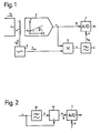
- FIG. 2 shows a detail of a variant of the circuit arrangement according to FIG. 1.
- 1 means a magnetic field sensor which is exposed to a magnetic field to be measured, outputs a voltage u at its output as a function of this magnetic field and thus works as a magnetic field / voltage converter.
- This magnetic field sensor 1 can, for. B. a Hall generator, a MOS magnetotransistor or a MOS magnetodiode.
- the slope a is a function of the temperature and is also subject to fluctuations due to aging, so that despite the good linearity of the transmission characteristic curve, an exact measurement of the magnetic field is not possible without special measures.
- the magnetic field sensor 1 can be used to measure a measuring current flowing in an electrical conductor 2 in the magnetic field generated by it.
- the coupling of the measuring current generated in the magnetic field into the magnetic field sensor 1 can take place in a known manner by means of a magnetic core or also without a magnetic core in that the magnetic field sensor 1 is arranged on the surface of the conductor 2 designed as a flat conductor.
- the current source 3 excites the solenoid 4 with an auxiliary current i h , which is an alternating current or a pulsating direct current.
- the magnetic coil 4 generates an alternating or pulsating auxiliary magnetic field of known size and with a known time profile. It is arranged so that this auxiliary field is superimposed on the magnetic field to be measured.
- the amplitude of the auxiliary field is a few percent of the maximum value of the amplitude of the magnetic field to be measured.
- the output of the magnetic field sensor 1 is connected to the signal input 8 of the analog / digital converter 7.
- the multiplier 5 has two inputs, one of which is connected to the output of the magnetic field sensor 1 and the other to the current source 3.
- the output of the multiplier 5 is connected to a reference voltage input 9 of the analog / digital converter 7 via the low pass 6.
- b m is the magnetic flux density generated by the measuring current and im and b h by the auxiliary current i h .
- u o is usually negligible and can be eliminated in the manner described below.
- the component i h caused by the auxiliary current can u h from the output voltage if necessary, by a not shown in the drawing, the filter to be filtered out, because the time course of this component is known.
- the analog / digital converter 7 converts the output voltage u or the component from m remaining after the elimination of the interfering components into a digital signal.
- the DC component V dc of this product corresponds to the portion of the output voltage u generated solely by the auxiliary magnetic field and is proportional to the slope a.
- the low pass 6 passes the direct current component V dc of the signal v and blocks the remaining components.
- the DC component V dc reaches the analog / digital converter 7 as a reference voltage.
- the transmission factor of the analog / digital converter 7 is proportional to the reciprocal of the reference voltage, so that this converter divides respectively. and the digital measurement result is independent of the slope a.
- the measuring device described is suitable for measuring alternating currents or alternating magnetic fields as well as direct currents or alternating magnetic fields.
- the time course of the auxiliary current i h is to be selected in such a way that correlations with the magnetic field to be measured are avoided.
- a sinusoidal auxiliary current i h with a frequency of a few kHz is suitable for measuring 50 Hz alternating fields.
- the current source 3 is particularly advantageous to design the current source 3 as a pseudo-random current source. If the time profile of the auxiliary current i h is rectangular, a polarity reversing switch can be used as the multiplier 5, which reverses the polarity of the output voltage u in time with the auxiliary current i h .
- the described compensation of fluctuations in the slope a ensures a high measurement accuracy and greatly reduces the requirements for the stability of the magnetic field sensor 1.
- the use of the analog / digital converter 7 as a division element results in a particularly simple circuit structure and eliminates the need for a stabilized DC voltage source for generating the reference voltage for this converter. Since the auxiliary magnetic field can be weak compared to the magnetic field to be measured, the generation of the auxiliary field requires a significantly lower power expenditure compared to the compensated transducer mentioned at the beginning.
- the filter mentioned advantageously consists of a low-pass element 10 and a subtractor element 11, the output of the magnetic field sensor 1 (FIG. 1) at the input of the low-pass element 10 and at the “+” input of the subtractor element 11, the output of the low-pass element 10 is connected to the "-" input of the subtracting element 11 and the output of the subtracting element 11 is connected to the signal input 8 of the analog / digital converter 7.
Landscapes
- Physics & Mathematics (AREA)
- Condensed Matter Physics & Semiconductors (AREA)
- General Physics & Mathematics (AREA)
- Measuring Magnetic Variables (AREA)
- Measurement Of Current Or Voltage (AREA)
- Arrangements For Transmission Of Measured Signals (AREA)
Description
- Die Erfindung bezieht sich auf eine Schaltungsanordnung zur Kompensation von Schwankungen des Übertragungsfaktors eines linearen Magnetfeldsensors der im Oberbegriff des Anspruchs 1 genannten Art.
- Es ist bekannt, einen elektrischen Strom über das von ihm erzeugte Magnetfeld potentialfrei zu messen. Zur Ermittlung der Stärke des Magnetfeldes dienen Magnetfeldsensoren, z. B. Hallgeneratoren, Magnetotransistoren und andere Halbleiterelemente, die ein zum Magnetfeld mehr oder weniger proportionales Ausgangssignal erzeugen. Um den Einfluss von Nichtlinearitäten und Schwankungen der Steigung der Übertragungskennlinie des Magnetfeldsensors auf das Messresultat zu eliminieren, kann mittels eines Regelkreises und einer Magnetspule ein magnetisches Gegenfeld erzeugt werden, welches das zu messende Magnetfeld praktisch vollständig kompensiert (DE-B-26 21 302). Nachteilig bei solchen sogenannten kompensierten Wandlern ist der verhältnismässig hohe Leistungsaufwand zur Erzeugung des kompensierenden Magnetfeldes.
- Manche der bekannten Magnetfeldsensoren zeichnen sich durch eine befriedigende Linearität der Übertragungskennlinie aus, wobei jedoch die Steigung der Übertragungskennlinie eine Funktion der Temperatur darstellt und auch alterungsbedingten Änderungen unterworfen ist. Es ist bekannt (EP-A-00 18 750), bei einem an sich linearen, als Magnetfeld/Frequenzwandler arbeitenden Magnetfeldsensor mit Hilfe eines magnetischen Gleichfeldes die Steigung der Übertragungskennlinie zu bestimmen und die Ausgangsfrequenz durch eine der Steigung proportionale Frequenz zu dividieren, so dass Schwankungen der Steigung kompensiert werden. Diese Art der Bestimmung der Steigung setzt jedoch voraus, dass einerseits das zu messende Magnetfeld ein reines Wechselfeld ist und das andererseits die Übertragungskennlinie des Magnetfeldsensors keinen Offset aufweist.
- Aus der DE-B-1 297 755 ist ausserdem eine Schaltungsanordnung bekannt, in der ein von einem Gleichstrom durchflossener magnetfeldabhängiger Widerstand einem zu messenden Magnetfeld ausgesetzt ist, dem ein sich z. B. zeitlich rechteckförmig schnell änderndes magnetisches Wechselfeld überlagert ist, welches mittels einer von einem Wechselstrom durchflossenen Spule erzeugt wird. Dabei wird eine Eigenschaft der magnetfeldabhängigen Widerstände ausgenutzt, nämlich dass die Symmetrie ihrer Kennlinie von Natur aus temperaturunabhängig ist, um ohne Kompensationsschaltung temperaturunabhängige Messungen zu realisieren.
- Der Erfindung liegt die Aufgabe zugrunde, eine Schaltungsanordnung der eingangs genannten Art mit einem Magnetfeld/Spannungswandler als Magnetfeldsensor zu bestücken und derart auszugestalten, dass durch Temperatur und Alterungseinflüsse bedingte Schwankungen der Steigung der Übertragungskennlinie des Magnetfeldsensors einwandfrei kompensiert werden.
- Die Lösung dieser Aufgabe gelingt durch die im Anspruch 1 angegebenen Merkmale.
- In einer bevorzugten Ausführung erfolgt die Kompensation auch dann einwandfrei, wenn der Magnetfeldsensor eine Offset-Spannung aufweist und wenn das zu messende Magnetfeld eine Gleichstromkomponente besitzt.
- Nachfolgend wird ein Ausführungsbeispiel der Erfindung anhand der Zeichnung näher erläutert.
- Es zeigen: Fig. 1 ein Prinzipschaltbild und
- Fig. 2 ein Detail einer Variante der Schaltungsanordnung nach der Fig. 1.
- In der Fig. 1 bedeutet 1 einen Magnetfeldsensor, der einem zu messenden Magnetfeld ausgesetzt ist, an seinem Ausgang eine Spannung u in Abhängigkeit von diesem Magnetfeld abgibt und somit als Magnetfeld/Spannungswandler arbeitet. Dieser Magnetfeldsensor 1 kann z. B. ein Hallgenerator, ein MOS-Magnetotransistor oder eine MOS-Magnetodiode sein. Für die Ausgangsspannung u des Magnetfeldsensors 1 gilt die Beziehung u=uo+a.b, wobei uo die gegebenenfalls vorhandene Offset-Spannung, a die Steigung der linearen Übertragungskennlinie und b die magnetische Flussdichte im Magnetfeldsensor 1 bedeutet. Die Steigung a ist eine Funktion der Temperatur und zudem auch alterungsbedingten Schwankungen unterworfen, so dass trotz der guten Linearität der Übertragungskennlinie ohne besondere Massnahmen eine genaue Messung des Magnetfeldes nicht möglich ist.
- Der Magnetfeldsensor 1 kann zur Messung eines in einem elektrischen Leiter 2 fliessenden Meßstromes im über das von ihm erzeugte Magnetfeld dienen. Die Einkopplung des vom Meßstrom im erzeugten Magnetfeldes in den Magnetfeldsensor 1 kann in bekannten Weise mittels eines Magnetkernes oder auch ohne einen Magnetkern dadurch erfolgen, dass der Magnetfeldsensor 1 auf der Oberfläche des als Flachleiter ausgebildeten Leiters 2 angeordnet wird.
- Mit Hilfe einer Stromquelle 3, einer Magnetspule 4 und eines aus einem Multiplikator 5 und einem Tiefpass 6 bestehenden Korrelators wird die Steigung a der Übertragungskennlinie bestimmt, und mittels eines als Divisionsglied arbeitenden Analog/Digitalwandlers 7 wird zur Kompensation von temperatur- oder alterungsbedingten Schwankungen der Steigung a die Division durchgeführt.
- Die Stromquelle 3 erregt die Magnetspule 4 mit einem Hilfsstrom ih, der ein Wechselstrom oder ein pulsierender Gleichstrom ist. Die Magnetspule 4 erzeugt ein alternierendes oder pulsierendes magnetisches Hilfsfeld bekannter Grösse und mit bekanntem zeitlichem Verlauf. Sie ist so angeordnet, dass dieses Hilfsfeld dem zu messenden Magnetfeld überlagert wird. Die Amplitude des Hilfsfeldes beträgt einige Prozent des Maximalwertes der Amplitude des zu messenden Magnetfeldes.
- Der Ausgang des Magnetfeldsensors 1 ist mit dem Signaleingang 8 des Analog/Digitalwandlers 7 verbunden. Der Multiplikator 5 besitzt zwei Eingänge, von denen der eine an den Ausgang des Magnetfeldsensors 1 und der andere an die Stromquelle 3 angeschlossen ist. Der Ausgang des Multiplikators 5 ist über den Tiefpass 6 an einen Referenzspannungseingang 9 des Analog/Digitalwandlers 7 angeschlossen.
- Die beschriebene Schaltungsanordnung arbeitet wie folgt:
- Der Magnetfeldsensor 1 erfasst die Summe des zu messenden Magnetfeldes und des vom Hilfsstrom ih erzeugten Magnetfeldes. Für die Ausgangsspannung u des Magnetfeldsensors 1 gilt
- u=uo+a(bm+bh)
- wobei bm die durch den Meßstrom und im und bh die durch den Hilfsstrom ih erzeugte magnetische Flussdichte bedeutet. uo ist in der Regel vernachlässigbar klein und kann auf die weiter unten beschriebene Weise eliminiert werden. Auch die durch den Hilfsstrom ih verursachte Komponente a.bh der Ausgangsspannung u kann erforderlichenfalls durch ein in der Zeichnung nicht dargestelltes Filter herausgefiltert werden, da der zeitliche Verlauf dieser Komponente bekannt ist. Der Analog/Digitalwandler 7 wandelt die Ausgangsspannung u bzw. die nach der Elimination der störenden Komponenten noch verbleibende Komponente a.bm in ein digitales Signal um.
- Der Multiplikator 5 bildet das Produkt v=u.ih der zeitveränderlichen Grössen u und ih. Die Gleichstromkomponente V dc dieses Produktes entspricht dem allein durch das Hilfsmagnetfeld erzeugten Anteil der Ausgangsspannung u und ist zur Steigung a proportional. Der Tiefpass 6 lässt die Gleichstromkomponente V dc des Signals v durch und sperrt dessen übrige Komponenten. Die Gleichstromkomponente Vdc gelangt als Referenzspannung zum Analog/Digitalwandler 7. Der Übertragungsfaktor des Analog/Digitalwandlers 7 ist proportional zum Reziprokwert der Referenzspannung, so dass dieser Wandler die Divisionbzw.
 durchführt und das digitale Messergebnis von der Steigung a unabhängig ist.
- Es ist leicht ersichtlich, dass die beschriebene Messeinrichtung sowohl zur Messung von Wechselströmen bzw. magnetischer Wechselfelder als auch von Gleichströmen bzw. magnetischer Gleichfelder geeignet ist. Der zeitliche Verlauf des Hilfsstromes ih ist derart zu wählen, dass Korrelationen mit dem zu messenden Magnetfeld vermieden werden. Zur Messung von 50 Hz-Wechselfeldern eignet sich beispielsweise ein sinusförmiger Hilfsstrom ih mit einer Frequenz von einigen kHz. Besonders vorteilhaft ist es, die Stromquelle 3 als Pseudo-Zufalls-Stromquelle auszubilden. Falls der zeitliche Verlauf des Hilfsstromes ih rechteckförmig ist, kann als Multiplikator 5 ein Umpolschalter verwendet werden, der die Polarität der Ausgangsspannung u im Takt des Hilfsstromes ih umpolt.
- Die beschriebene Kompensation von Schwankungen der Steigung a gewährleistet eine hohe Messgenauigkeit und reduziert in hohem Masse die Anforderungen an die Stabilität des Magnetfeldsensors 1. Die Verwendung des Analog/Digitalwandlers 7 als Divisionsglied ergibt einen besonders einfachen Schaltungsaufbau und erübrigt eine stabilisierte Gleichspannungsquelle zur Erzeugung der Referenzspannung für diesen Wandler. Da das magnetische Hilfsfeld gegenüber dem zu messenden Magnetfeld schwach sein kann, erfordert die Erzeugung des Hilfsfeldes im Vergleich zu dem eingangs erwähnten kompensierten Wandlers einen wesentlich geringeren Leistungsaufwand.
- Wenn eine allfällige Gleichfeldkomponente des zu messenden Magnetfeldes von der Messung nicht erfasst werden soll, kann zwischen den Ausgang des Magnetfeldsensors 1 und den Signaleingang 8 des Analog/Digitalwandlers 7 ein Filter geschaltet werden, das die in der Ausgangsspannung u enthaltene Gleichstromkomponente sperrt. Durch diese Massnahme wird auch die Offset-Spannung uo des Magnetfeldsensors 1 eliminiert. Das genannte Filter besteht gemäss der Fig. 2 vorteilhaft aus einem Tiefpassglied 10 und einem Subtrahierglied 11, wobei der Ausgang des Magnetfeldsensors 1 (Fig. 1) an den Eingang des Tiefpassgliedes 10 sowie an den "+"-Eingang des Subtrahiergliedes 11, der Ausgang des Tiefpassgliedes 10 an den "-"-Eingang des Subtrahiergliedes 11 und der Ausgang des Subtrahiergliedes 11 an den Signaleingang 8 des Analog/Digitalwandlers 7 angeschlossen ist. Die Gleichstromkomponente ü der Ausgangsspannung u gelangt über das Tiefpassglied 10 zum Subtrahierglied 11, an dessen Ausgang das Differenzsignal w = u-ü entsteht.
- Schliesslich ist es auch möglich, die Elimination der Gleichstromkomponente ü erst nach der Analog/Digitalumwandlung durch digitale Filterung vorzunehmen.
Claims (5)
Priority Applications (1)
| Application Number | Priority Date | Filing Date | Title |
|---|---|---|---|
| AT84104472T ATE35867T1 (de) | 1983-08-08 | 1984-04-19 | Schaltungsanordnung zur kompensation von schwankungen des uebertragungsfaktors eines linearen magnetfeldsensors. |
Applications Claiming Priority (2)
| Application Number | Priority Date | Filing Date | Title |
|---|---|---|---|
| CH4448/83 | 1983-08-08 | ||
| CH4448/83A CH661359A5 (de) | 1983-08-08 | 1983-08-08 | Schaltungsanordnung zur kompensation von schwankungen des uebertragungsfaktors eines linearen magnetfeldsensors. |
Publications (2)
| Publication Number | Publication Date |
|---|---|
| EP0137896A1 EP0137896A1 (de) | 1985-04-24 |
| EP0137896B1 true EP0137896B1 (de) | 1988-07-20 |
Family
ID=4276311
Family Applications (1)
| Application Number | Title | Priority Date | Filing Date |
|---|---|---|---|
| EP84104472A Expired EP0137896B1 (de) | 1983-08-08 | 1984-04-19 | Schaltungsanordnung zur Kompensation von Schwankungen des Uebertragungsfaktors eines linearen Magnetfeldsensors |
Country Status (4)
| Country | Link |
|---|---|
| EP (1) | EP0137896B1 (de) |
| AT (1) | ATE35867T1 (de) |
| CH (1) | CH661359A5 (de) |
| DE (1) | DE3472840D1 (de) |
Families Citing this family (4)
| Publication number | Priority date | Publication date | Assignee | Title |
|---|---|---|---|---|
| CH664632A5 (de) * | 1984-08-16 | 1988-03-15 | Landis & Gyr Ag | Schaltungsanordnung zur kompensation von schwankungen des uebertragungsfaktors eines magnetfeldsensors. |
| DE19538757C1 (de) * | 1995-10-18 | 1997-03-06 | Vdo Schindling | Magnetfeldsensor |
| US5696575A (en) * | 1996-04-23 | 1997-12-09 | Hughes Aircraft | Digital flux gate magnetometer |
| DE19903296A1 (de) * | 1999-01-28 | 2000-08-24 | Bosch Gmbh Robert | Vorrichtung und Verfahren zur Bestimmung eines Magnetfeldes |
Family Cites Families (4)
| Publication number | Priority date | Publication date | Assignee | Title |
|---|---|---|---|---|
| DE1297755B (de) * | 1963-05-10 | 1969-06-19 | Siemens Ag | Magnetfeldmessgeraet mit einer Sonde mit magnetfeldabhaengigem Widerstand |
| US4013946A (en) * | 1975-04-02 | 1977-03-22 | Harnessed Energies, Inc. | Means for determining a first magnetic field direction by measuring secondary magnetic fields induced in a body rotated in said first field |
| DE2719073B1 (de) * | 1977-04-29 | 1978-06-22 | Grundig Emv | Verfahren zur Erkennung der Induktion Null mittels einer Feldplatte |
| DE3061485D1 (en) * | 1979-05-04 | 1983-02-03 | Gen Electric Co Plc | Carrier-domain magnetometers |
-
1983
- 1983-08-08 CH CH4448/83A patent/CH661359A5/de not_active IP Right Cessation
-
1984
- 1984-04-19 AT AT84104472T patent/ATE35867T1/de not_active IP Right Cessation
- 1984-04-19 EP EP84104472A patent/EP0137896B1/de not_active Expired
- 1984-04-19 DE DE8484104472T patent/DE3472840D1/de not_active Expired
Also Published As
| Publication number | Publication date |
|---|---|
| ATE35867T1 (de) | 1988-08-15 |
| DE3472840D1 (en) | 1988-08-25 |
| CH661359A5 (de) | 1987-07-15 |
| EP0137896A1 (de) | 1985-04-24 |
Similar Documents
| Publication | Publication Date | Title |
|---|---|---|
| EP0172402B1 (de) | Schaltungsanordnung zur Kompensation von Schwankungen des Uebertragungsfaktors eines Magnetfeldsensors | |
| DE3133019C2 (de) | ||
| DE2744845C3 (de) | Verfahren zur Kompensation der elektrochemischen Störgleichspannung bei der magnetisch-induktiven Durchflußmessung mit periodisch umgepoltem magnetischem Gleichfeld | |
| DE69422222T2 (de) | Magnetisch-induktiver Durchflussmesser und dazu gehöriges Messprinzip | |
| DE69425160T2 (de) | Vorrichtung zur messung von materialeigenschaft | |
| DE112009000449T5 (de) | Beseitigung des Hystereseversatzes bei magnetischen Sensoren | |
| WO2012098054A1 (de) | Strommessvorrichtung | |
| DE3322942C2 (de) | Schaltung zur Messung der magnetischen Induktion mit einer Hall-Feldsonde | |
| DE3642771C2 (de) | ||
| DE102007038225B4 (de) | Hochstabiles kapazitives Messsystem für extreme Einsatzbedingungen | |
| DE10224354C1 (de) | Schaltungsanordnung und Verfahren zur Kompensation von Änderungen eines Übertragungsfaktors einer Magnetfeldsensoranordnung | |
| EP2905627B1 (de) | Vorrichtung und Verfahren zur kontaktlosen, präzisen Messung des Gleichstromanteils in einem Mischstrom | |
| DE3832568A1 (de) | Schaltungsanordnung zur temperaturkompensation von kapazitiven druck- und differenzdrucksensoren | |
| EP0137896B1 (de) | Schaltungsanordnung zur Kompensation von Schwankungen des Uebertragungsfaktors eines linearen Magnetfeldsensors | |
| DE2837113A1 (de) | Anordnung zur erregung eines elektromagneten eines magnetischen stroemungsmessers | |
| DE69033966T2 (de) | Sender | |
| EP0329652B1 (de) | Vorrichtung zur messung eines zeitlich konstanten oder sich ändernden magnetfeldes | |
| EP0250028B1 (de) | Schaltungsanordnung zur Kompensation von temperatur- und nichttemperatur-bedingtem Driften eines kapazitiven Sensors | |
| DE102007032300A1 (de) | Stromsensor zur Gleich- oder Wechselstrommessung | |
| DE10334517B4 (de) | Messgerät für elektrische Energie für ein Wechselstromnetz | |
| DE102004056384A1 (de) | Verfahren zur Offseteliminierung aus Signalen magnetoresistiver Sensoren | |
| EP0814324A1 (de) | Messverstärker-Anordnungen von magnetisch-induktiven Durckflussmessern | |
| DE2827267C2 (de) | Restspannungs-Regelschaltung für ein Hall-Element | |
| DE102019120666B3 (de) | Sensorvorrichtung zur breitbandigen Messung von elektrischen Strömen durch einen Leiter und Verfahren zur breitbandigen Messung | |
| EP0438637A1 (de) | Verfahren und Anordnung zur Ermittlung eines Effektivwertes Ieff eines mit Hilfe eines Hallelementes und einer Verstärkeranordnung zu messenden Stromes |
Legal Events
| Date | Code | Title | Description |
|---|---|---|---|
| PUAI | Public reference made under article 153(3) epc to a published international application that has entered the european phase |
Free format text: ORIGINAL CODE: 0009012 |
|
| AK | Designated contracting states |
Designated state(s): AT DE FR GB NL SE |
|
| 17P | Request for examination filed |
Effective date: 19850518 |
|
| 17Q | First examination report despatched |
Effective date: 19861030 |
|
| GRAA | (expected) grant |
Free format text: ORIGINAL CODE: 0009210 |
|
| AK | Designated contracting states |
Kind code of ref document: B1 Designated state(s): AT DE FR GB NL SE |
|
| REF | Corresponds to: |
Ref document number: 35867 Country of ref document: AT Date of ref document: 19880815 Kind code of ref document: T |
|
| GBT | Gb: translation of ep patent filed (gb section 77(6)(a)/1977) | ||
| REF | Corresponds to: |
Ref document number: 3472840 Country of ref document: DE Date of ref document: 19880825 |
|
| ET | Fr: translation filed | ||
| PLBE | No opposition filed within time limit |
Free format text: ORIGINAL CODE: 0009261 |
|
| STAA | Information on the status of an ep patent application or granted ep patent |
Free format text: STATUS: NO OPPOSITION FILED WITHIN TIME LIMIT |
|
| 26N | No opposition filed | ||
| PGFP | Annual fee paid to national office [announced via postgrant information from national office to epo] |
Ref country code: GB Payment date: 19900331 Year of fee payment: 7 |
|
| PGFP | Annual fee paid to national office [announced via postgrant information from national office to epo] |
Ref country code: FR Payment date: 19900407 Year of fee payment: 7 |
|
| PGFP | Annual fee paid to national office [announced via postgrant information from national office to epo] |
Ref country code: AT Payment date: 19900411 Year of fee payment: 7 |
|
| PGFP | Annual fee paid to national office [announced via postgrant information from national office to epo] |
Ref country code: SE Payment date: 19900420 Year of fee payment: 7 |
|
| PGFP | Annual fee paid to national office [announced via postgrant information from national office to epo] |
Ref country code: NL Payment date: 19900430 Year of fee payment: 7 |
|
| PGFP | Annual fee paid to national office [announced via postgrant information from national office to epo] |
Ref country code: DE Payment date: 19900502 Year of fee payment: 7 |
|
| PG25 | Lapsed in a contracting state [announced via postgrant information from national office to epo] |
Ref country code: GB Effective date: 19910419 Ref country code: AT Effective date: 19910419 |
|
| PG25 | Lapsed in a contracting state [announced via postgrant information from national office to epo] |
Ref country code: SE Effective date: 19910420 |
|
| PG25 | Lapsed in a contracting state [announced via postgrant information from national office to epo] |
Ref country code: NL Effective date: 19911101 |
|
| NLV4 | Nl: lapsed or anulled due to non-payment of the annual fee | ||
| GBPC | Gb: european patent ceased through non-payment of renewal fee | ||
| PG25 | Lapsed in a contracting state [announced via postgrant information from national office to epo] |
Ref country code: FR Effective date: 19911230 |
|
| PG25 | Lapsed in a contracting state [announced via postgrant information from national office to epo] |
Ref country code: DE Effective date: 19920201 |
|
| REG | Reference to a national code |
Ref country code: FR Ref legal event code: ST |
|
| EUG | Se: european patent has lapsed |
Ref document number: 84104472.0 Effective date: 19911108 |