EP0137569A2 - Screen printing device - Google Patents
Screen printing device Download PDFInfo
- Publication number
- EP0137569A2 EP0137569A2 EP84201434A EP84201434A EP0137569A2 EP 0137569 A2 EP0137569 A2 EP 0137569A2 EP 84201434 A EP84201434 A EP 84201434A EP 84201434 A EP84201434 A EP 84201434A EP 0137569 A2 EP0137569 A2 EP 0137569A2
- Authority
- EP
- European Patent Office
- Prior art keywords
- mask
- printing device
- template
- screen
- screen printing
- Prior art date
- Legal status (The legal status is an assumption and is not a legal conclusion. Google has not performed a legal analysis and makes no representation as to the accuracy of the status listed.)
- Granted
Links
Images


Classifications
-
- B—PERFORMING OPERATIONS; TRANSPORTING
- B41—PRINTING; LINING MACHINES; TYPEWRITERS; STAMPS
- B41F—PRINTING MACHINES OR PRESSES
- B41F15/00—Screen printers
-
- H—ELECTRICITY
- H05—ELECTRIC TECHNIQUES NOT OTHERWISE PROVIDED FOR
- H05K—PRINTED CIRCUITS; CASINGS OR CONSTRUCTIONAL DETAILS OF ELECTRIC APPARATUS; MANUFACTURE OF ASSEMBLAGES OF ELECTRICAL COMPONENTS
- H05K3/00—Apparatus or processes for manufacturing printed circuits
- H05K3/10—Apparatus or processes for manufacturing printed circuits in which conductive material is applied to the insulating support in such a manner as to form the desired conductive pattern
- H05K3/12—Apparatus or processes for manufacturing printed circuits in which conductive material is applied to the insulating support in such a manner as to form the desired conductive pattern using thick film techniques, e.g. printing techniques to apply the conductive material or similar techniques for applying conductive paste or ink patterns
- H05K3/1216—Apparatus or processes for manufacturing printed circuits in which conductive material is applied to the insulating support in such a manner as to form the desired conductive pattern using thick film techniques, e.g. printing techniques to apply the conductive material or similar techniques for applying conductive paste or ink patterns by screen printing or stencil printing
-
- B—PERFORMING OPERATIONS; TRANSPORTING
- B41—PRINTING; LINING MACHINES; TYPEWRITERS; STAMPS
- B41F—PRINTING MACHINES OR PRESSES
- B41F15/00—Screen printers
- B41F15/08—Machines
- B41F15/0804—Machines for printing sheets
-
- B—PERFORMING OPERATIONS; TRANSPORTING
- B41—PRINTING; LINING MACHINES; TYPEWRITERS; STAMPS
- B41F—PRINTING MACHINES OR PRESSES
- B41F15/00—Screen printers
- B41F15/14—Details
- B41F15/16—Printing tables
-
- Y—GENERAL TAGGING OF NEW TECHNOLOGICAL DEVELOPMENTS; GENERAL TAGGING OF CROSS-SECTIONAL TECHNOLOGIES SPANNING OVER SEVERAL SECTIONS OF THE IPC; TECHNICAL SUBJECTS COVERED BY FORMER USPC CROSS-REFERENCE ART COLLECTIONS [XRACs] AND DIGESTS
- Y10—TECHNICAL SUBJECTS COVERED BY FORMER USPC
- Y10S—TECHNICAL SUBJECTS COVERED BY FORMER USPC CROSS-REFERENCE ART COLLECTIONS [XRACs] AND DIGESTS
- Y10S101/00—Printing
- Y10S101/36—Means for registering or alignment of print plates on print press structure
Definitions
- the present invention relates to a screen printing device including a work table having a printing position, means on said work table for holding an object, e.g. a substrate, in said printing position, a holder for a screen provided with a mask, a microscope and means for adjusting the relative positions of said table, said screen holder and said microscope.
- Such a screen printing device for printing on a substrate is well known in the art, e.g. the Model 155 S Screen Printer manufactured by the PRESCO division of the US firm AMI (Affiliated Manufacturers Inc.).
- the work table is movable from an initial position located below an adjustable film holder to a printing position located below the screen mask holder and vice versa.
- the device operates as follows. After a reference film - usually the photopositive from which the mask was imaged - has been inserted in the film holder and an auxiliary substrate has been positioned on the work table, the latter is moved into its printing position and at least one trial print is made on this auxiliary substrate.
- the work table with the auxiliary substrate is brought back into its initial position under the film holder the position of which is then adjusted with respect to the print on the auxiliary substrate with the help of the microscope and of film holder ajustment means until reference strips on the film exactly match with reference strips on the auxiliary substrate.
- the printed auxiliary substrate is then removed as the device is ready for making a same but definitive print on several substrates. Prior to each such a printing operation reference strips on each of these substrates must however be aligned with the reference strips on the film by means of the microscope and of work table adjustment means.
- An object of the present invention is to provide a screen printing device of the above type but which does not need a trial print and wherein the alignement of the mask and the object is enabled in an easy, fast and accurate way.
- the device further includes a template with reference portions corresponding to reference portions of said mask and that said work table has at least one hole with associated illumination means to simultaneously illuminate said corresponding reference portions of said mask and of said template held in said printing position by said holding means in order to be able to adjust, with the help of said adjustment means, the relative position of said reference portions when viewed through said microscope.
- the template is positioned in the printing position of the work table and held therein by the holding means. Then the screen holder carrying the mask is brought in the immediate proximity of the template in such a way that both reference portions of the mask and corresponding reference portions of the template are located in the center of an illuminated hole of the work table and may be simultaneously viewed through the microscope. With the help of the adjusting means the reference portions of the mask are then alligned with those of the template so that this mask is then correctly positioned with respect to the printing position on the work table. The device is then ready for executing a printing operation on a substrate when the latter is substituted for the template in the printing position.
- a number of electric circuits can be successively printed in a same surface of a substrate and thus be used to produce a multilayer printed circuit.
- This device includes, among many other elements, an adjustable work table 1 (Figs. 1, 2), an adjustable screen holder mounted above the work table 1, a movable squeegee arranged above the screen holder, an adjustable microscope mounted above the screen holder, and means to adjust the position of the work table 1, the screen holder and the micro- ; scope. Because they are well known in the art and moreover not needed to explain the invention the squeegee, the screen holder and the microscope and their associated adjustable positioning means are not represented. Also the adjustable positioning means of the work table 1 are not shown.
- the work table 1 (Figs. 1-4) has a printing position 2 for a substrate 3 which is schematically represented in dash-dot lines and is provided with a cavity which houses a device, generally indicated by reference numeral 4, for correctly positioning the substrate 3 in this printing position 2.
- the printing position 2 is delimited by three stationary cylindrical abutments 5, 6, 7 and by a movable abutment 8 forming part of the positioning device 4.
- the table 1 is further provided with 25 cylindrical suction holes, such as 9 to 13, arranged in a square matrix of 5 rows and 5 columns, and three cylindrical positioning holes 14, 15 and 16 the centres of which are disposed at the apexes of a right-angled triangle whose orthogonal sides are parallel to the sides of the right-angled triangle formed by the abutments 5, 6 and 7.
- the rows and columns of the square matrix formed by the suction holes are also parallel to these orthogonal sides.
- the suction holes such as 9 to 13 communicate with a vacuum chamber 17 (Fig. 4) which is closed at the bottom by a cover 18 and communicates with a pump (not shown) through a conduit 19.
- Light guides 20, 21, and 22 are mounted in the positioning holes 14, 15 and 16 respectively and are each illuminated by an associated lamp, such as 23 and 24 shown in Fig. 4.
- the positioning device 4 (Figs. 1 and 5 to 9) includes a positioning mechanism 25 mounted in a cavity 26 of the work table 1 and a control rod 27 for this mechanism, mounted in a cylindrical bore 28 of this table 1 (Fig. 1).
- the positioning mechanism 25 comprises a cylindrical body 29, an L-shaped lever 30 and a helical spring 31.
- the cylindrical body 29 has two upper lateral flanges 32 and 33 with chamfered screw holes 34 and 35 respectively, and a recess 36 extending at the front side over the whole height of the body and at the rear side only over part of this height considered from the bottom of the body.
- the body 29 further presents two coaxial cylindrical bores 37 and 38 which open in the cavity 36 and a cylindrical blind bore 39 which is perpendicular to the bores 37 and 38 whose axes are parallel to a line joining the centres of the screw holes 34 and 35.
- the L-shaped lever 30 is provided with the above mentioned abutment 8 made of Widia steel at one of its ends and further has a cylindrical hole 40 and a cylindrical blind bore 41. It is pivotally mounted in the body 29 by means of an axle 42 mounted in the bores 37, 38 and hole 4 0 .
- the above mentioned spring 31 is arranged in the bores 39 and 41 of the body 29 and the lever 30 respectively.
- the latter lever 30 is continuously urged into an operative position wherein its longest arm abuts against the upper edge 43 (Fig. 7) of the recess 36, and wherein the abutment 8 protrudes out of the body 29 and is able to make contact with a corresponding corner of the substrate 3.
- the control rod 27 has one end with a semi-circular cross-section and another end provided with a control knob 44. By rotating the rod 27 with the help of knob 44 the lever 30 is pivoted from an operative position to an inactive position or vice versa.
- the screen of the above mentioned screen holder (not shown) of the present screen printing device carries an emulsion of which parts constituting a mask 45 are removed.
- a portion of this mask is shown in Fig. lO, the black parts constituting the mask itself, i.e. openings in the emulsion, and the white parts being constituted by the emulsion.
- the portion of the mask 45 shown includes an electric circuit 46 of which only the square periphery is represented and reference portions 47 to 50 which are arranged along the orthogonal sides of a right-angled triangle with the portions 47 and 48 in line with an edge of the circuit 46.
- the mask portions 47, 49 and 48 are shown on an enlarged scale in Figs. 11 and 12 respectively.
- the reference portions 47 and 49 are joined by a corner piece 51.
- Reference portion 47 is constituted by a number of staircase-shaped portions comprising aligned recti-3Lnear first reference strips such as 52, 53 and aligned second and third rectilinear strips such as 54, 55 and 56, 57 which are at a distance Dl (Fig. 16), D2 (not shown) from the aligned first reference strips 52, 53.
- These distances have been chosen in function of the parameters of different screens on which a mask may be formed, i.e. the opening 0 (Fig. 16) which is the distance between two adjacent screen wires and the diameter d of these wires. More particularly as shown on Fig. 16. This relation has been empirically obtained and is such that at least one wire 87 (Fig. 16) of the screen is located in the area delimited by the aligned first reference strips such as 52, and the aligned second strips, such as 54 and such that this wire is at a sufficient distance from these strips.
- reference portion 49 is constituted by a number of staircase-shaped portions comprising first reference strips 58, 59 and second and third strips 60, 61 and 62, 63.
- Reference portion 48 comprises first reference strips 64, 65 and second and third strips 66, 67 and 68, 69.
- the present screen printing device also includes a template 70 (Figs. 2 and 13-15) with a thicker square central body 71 having a shape and size identical to those of the substrate 3 and thinner end flanges 72, 73 and 74.
- the body 71 and the flanges 72 to 74 have a common upper plane (Fig. 2, 13). Asvisible on Fig. 2, these end flanges have a length equal to the distance between the body 71 and the centre of the openings 14, 15 and 16 of the work table 1.
- the width of end flange 72 is equal to that of the body 71, whereas that of the end flanges 73, 74 is such that the template 70 maybe positioned in the printing position 2 without being hindered by the abutment 7.
- the abutment 8 can be brought into contact with the adjacent corner point of the body 71 of the template 70 (Fig. 2) to correctly position the latter in the printing position 2, just as the above mentioned substrate 3.
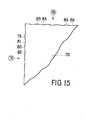
- the edge flanges 73, 72 and 74 have staircase-shaped reference portions 75, 76; 77 and 78 respectively which are arranged along the orthogonal sides of a right-angled triangle and of which 75 and 76 are represented on an enlarged scale in Fig. 15, this scale being the same as that of Fig. 11 and 12.
- the reference portion 75 comprises aligned rectilinear first strips such as 79 and 80 and aligned rectilinear second strips such as 81 and 82 and the reference portion 76 likewise comprises aligned first reference strips 83 and 84 and aligned second strips 85 and 86.
- the strips 81, 82 and 85, 86 are e.g. at a distance equal to 0.03 mm from the aligned strips 79, 80 and 83, 84 respectively.
- the reference portions 77 and 78 are similar to 75 and 76.
- the above described screen printing device operates as follows.
- the template 70 is brought in the printing position 2 of the work table 1.
- the movable abutment 8 is made to exert a pressure on the adjacent corner point of the body part 71 of the template 70 two sides of which are thus brought into contact with the abutments 5, 6 and 7.
- this template 70 is correctly positioned in the printing position 2.
- the screen holder carrying the mask 45 is then brought in the immediate proximity of the template 7 0 and in such a way that either one of the pairs of reference portions 47 and 75, 48 and 77, 49 and 76 or 50 and 78 can be simultaneously viewed in the microscope.
- the reference portions 75 and 76 of the template 70 and 47 and 49 of the mask 45 are viewed, then one sees these portions on an enlarged scale as shown in Figs. 15 and 11 respectively.
- the reference strips such as 52 and 53 of the mask 45 are aligned with the reference strips such as 79 and 80 of the template 70.
- the reference strips such as 58 and 59 of the mask are aligned with the reference strips such as 83 and 84 of the template 70.
- Fig. 16 shows screen wire 88 partially covered by reference strip 52 of the edge of the mask edge 45.
- a substrate 3 is substituted for the template 70 and correctly positioned in the printing position 2.
- this substrate 3 exactly has the same shape and size as the body 71 of the template 70, it is automatically correctly positioned with respect to the mask 45.
- the device is now ready for a series of printing operations.
- the template 7 0 is substituted for the substrate 3 and aligned with a new mask,etc. Thus one is sure that the various layers printed in succession on the substrate are correctly aligned.
Abstract
Description
- The present invention relates to a screen printing device including a work table having a printing position, means on said work table for holding an object, e.g. a substrate, in said printing position, a holder for a screen provided with a mask, a microscope and means for adjusting the relative positions of said table, said screen holder and said microscope.
- Such a screen printing device for printing on a substrate is well known in the art, e.g. the Model 155 S Screen Printer manufactured by the PRESCO division of the US firm AMI (Affiliated Manufacturers Inc.). In this known device the work table is movable from an initial position located below an adjustable film holder to a printing position located below the screen mask holder and vice versa. To make a same print on several substrates the device operates as follows. After a reference film - usually the photopositive from which the mask was imaged - has been inserted in the film holder and an auxiliary substrate has been positioned on the work table, the latter is moved into its printing position and at least one trial print is made on this auxiliary substrate. Thereafter, the work table with the auxiliary substrate is brought back into its initial position under the film holder the position of which is then adjusted with respect to the print on the auxiliary substrate with the help of the microscope and of film holder ajustment means until reference strips on the film exactly match with reference strips on the auxiliary substrate. The printed auxiliary substrate is then removed as the device is ready for making a same but definitive print on several substrates. Prior to each such a printing operation reference strips on each of these substrates must however be aligned with the reference strips on the film by means of the microscope and of work table adjustment means.
- Summarizing, with the known device, when a same print has to be made on several substrates, first a number of preparatory operations (trial print, film holder adjustment) have to be performed in common for all these substrates, and prior to each definitive printing operation on a substrate a work table adjustment has to be executed. Also several prints may be successively made on a same substrate by proceeding in the above described way for each such print. But because prior to each print a reference film has to be aligned with the reference strips on the substrate, it is clear that the precision with which each print is executed decreases with the number of prints as the alignement errors cumulate.
- An object of the present invention is to provide a screen printing device of the above type but which does not need a trial print and wherein the alignement of the mask and the object is enabled in an easy, fast and accurate way.
- According to the invention this object is achieved due to the fact that the device further includes a template with reference portions corresponding to reference portions of said mask and that said work table has at least one hole with associated illumination means to simultaneously illuminate said corresponding reference portions of said mask and of said template held in said printing position by said holding means in order to be able to adjust, with the help of said adjustment means, the relative position of said reference portions when viewed through said microscope.
- In this screen printing device, first the template is positioned in the printing position of the work table and held therein by the holding means. Then the screen holder carrying the mask is brought in the immediate proximity of the template in such a way that both reference portions of the mask and corresponding reference portions of the template are located in the center of an illuminated hole of the work table and may be simultaneously viewed through the microscope. With the help of the adjusting means the reference portions of the mask are then alligned with those of the template so that this mask is then correctly positioned with respect to the printing position on the work table. The device is then ready for executing a printing operation on a substrate when the latter is substituted for the template in the printing position. Hence, no trial print is necessary and once the position of the mask has been fixed successive substrates may be printed without any further adjustment. This obviously increases the speed of production and ensures a correct and constant alignement for all the substrates. In case a number of consecutive prints with different masks has to be made on a same substrate, the previously described alignement has to be executed between each mask and the template prior to each print. But because each of these alignements is performed with respect to the same references on the template, possible positioning errors never cumulate so that the accuracy obtained is very high.
- The above mentioned and other objects and features of the invention will become more apparent and the invention itself will be best understood by referring to the following description of an embodiment taken in conjunction with the accompanying drawings in which :
- Fig. 1 is a top plan view of a work table 1, a substrate 3 and a
positioning mechanism 4 of a screen printing device according to the invention; - Fig. 2 is a top plan view of part of the work table 1 of Fig. 1 with a
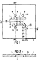
template 70 positioned thereon; - Fig. 3 is a cross-section along line III-III of part of Fig. 1 considered in the direction of the arrows;
- Fig. 4 is a cross-section along line IV-IV of Fig. 1 considered in the direction of the arrows;
- Fig. 5 is a top plan view of the
positioning mechanism 4 of Fig. 1 but on an enlarged scale; - Fig. 6 is a side view of Fig. 5 in the direction of arrow VI;
- Fig. 7 is a front view of Fig. 5 in the direction of arrow VII but with
lever 30 removed: - Fig. 8 is a side view of this
lever 30; - Fig- 9 is a front view of Fig. 8 in the direction of arrow IX;
- Fig. 10 is a top plan view of a mask formed on a screen of a screen printing device according to the invention;
- Figs. 11 and 12 are top plan view on an enlarged scale of
parts - Fig. 13 is a top plan view of the
template 70 already shown in Fig. 2; - Fig. 14 is a side view of Fig. 13; in the direction of arrow XIV.
- Fig. 15 is a top plan view on the same scale as Fig. 12, of
parts template 70 of Fig. 13; - Fig. 16 shows parts of the
template 70 of Fig. 15 superposed on part of themask 45 of Fig. 11 but on an enlarged scale. - With the present screen printing device a number of electric circuits can be successively printed in a same surface of a substrate and thus be used to produce a multilayer printed circuit.
- This device includes, among many other elements, an adjustable work table 1 (Figs. 1, 2), an adjustable screen holder mounted above the work table 1, a movable squeegee arranged above the screen holder, an adjustable microscope mounted above the screen holder, and means to adjust the position of the work table 1, the screen holder and the micro- ; scope. Because they are well known in the art and moreover not needed to explain the invention the squeegee, the screen holder and the microscope and their associated adjustable positioning means are not represented. Also the adjustable positioning means of the work table 1 are not shown.
- The work table 1 (Figs. 1-4) has a
printing position 2 for a substrate 3 which is schematically represented in dash-dot lines and is provided with a cavity which houses a device, generally indicated byreference numeral 4, for correctly positioning the substrate 3 in thisprinting position 2. Theprinting position 2 is delimited by three stationarycylindrical abutments movable abutment 8 forming part of thepositioning device 4. The table 1 is further provided with 25 cylindrical suction holes, such as 9 to 13, arranged in a square matrix of 5 rows and 5 columns, and threecylindrical positioning holes abutments cover 18 and communicates with a pump (not shown) through aconduit 19.Light guides positioning holes - The positioning device 4 (Figs. 1 and 5 to 9) includes a
positioning mechanism 25 mounted in acavity 26 of the work table 1 and acontrol rod 27 for this mechanism, mounted in acylindrical bore 28 of this table 1 (Fig. 1). - The
positioning mechanism 25 comprises acylindrical body 29, an L-shaped lever 30 and ahelical spring 31. Thecylindrical body 29 has two upperlateral flanges chamfered screw holes recess 36 extending at the front side over the whole height of the body and at the rear side only over part of this height considered from the bottom of the body. Thebody 29 further presents two coaxialcylindrical bores cavity 36 and a cylindricalblind bore 39 which is perpendicular to thebores screw holes - The L-
shaped lever 30 is provided with the above mentionedabutment 8 made of Widia steel at one of its ends and further has acylindrical hole 40 and a cylindricalblind bore 41. It is pivotally mounted in thebody 29 by means of anaxle 42 mounted in thebores hole 40. The above mentionedspring 31 is arranged in thebores body 29 and thelever 30 respectively. Thus thelatter lever 30 is continuously urged into an operative position wherein its longest arm abuts against the upper edge 43 (Fig. 7) of therecess 36, and wherein theabutment 8 protrudes out of thebody 29 and is able to make contact with a corresponding corner of the substrate 3. - The
control rod 27 has one end with a semi-circular cross-section and another end provided with acontrol knob 44. By rotating therod 27 with the help ofknob 44 thelever 30 is pivoted from an operative position to an inactive position or vice versa. - The screen of the above mentioned screen holder (not shown) of the present screen printing device carries an emulsion of which parts constituting a
mask 45 are removed. A portion of this mask is shown in Fig. lO, the black parts constituting the mask itself, i.e. openings in the emulsion, and the white parts being constituted by the emulsion. The portion of themask 45 shown includes anelectric circuit 46 of which only the square periphery is represented and referenceportions 47 to 50 which are arranged along the orthogonal sides of a right-angled triangle with theportions circuit 46. Themask portions reference portions corner piece 51.Reference portion 47 is constituted by a number of staircase-shaped portions comprising aligned recti-3Lnear first reference strips such as 52, 53 and aligned second and third rectilinear strips such as 54, 55 and 56, 57 which are at a distance Dl (Fig. 16), D2 (not shown) from the alignedfirst reference strips 
- Likewise
reference portion 49 is constituted by a number of staircase-shaped portions comprising first reference strips 58, 59 and second andthird strips Reference portion 48 comprises first reference strips 64, 65 and second andthird strips - The present screen printing device also includes a template 70 (Figs. 2 and 13-15) with a thicker square
central body 71 having a shape and size identical to those of the substrate 3 andthinner end flanges body 71 and theflanges 72 to 74 have a common upper plane (Fig. 2, 13). Asvisible on Fig. 2, these end flanges have a length equal to the distance between thebody 71 and the centre of theopenings end flange 72 is equal to that of thebody 71, whereas that of theend flanges template 70 maybe positioned in theprinting position 2 without being hindered by theabutment 7. As theend flanges 72 to 74 are at a certain distance from the upper surface of the work table 1 when the template is in theprinting position 2, theabutment 8 can be brought into contact with the adjacent corner point of thebody 71 of the template 70 (Fig. 2) to correctly position the latter in theprinting position 2, just as the above mentioned substrate 3. - The edge flanges 73, 72 and 74 have staircase-shaped
reference portions reference portion 75 comprises aligned rectilinear first strips such as 79 and 80 and aligned rectilinear second strips such as 81 and 82 and thereference portion 76 likewise comprises aligned first reference strips 83 and 84 and alignedsecond strips 85 and 86. Thestrips reference portions - The above described screen printing device operates as follows.
- After the
mask 45 has been formed on the screen of the screen holder, thetemplate 70 is brought in theprinting position 2 of the work table 1. By rotating thecontrol rod 27 of thepositioning device 4 themovable abutment 8 is made to exert a pressure on the adjacent corner point of thebody part 71 of thetemplate 70 two sides of which are thus brought into contact with theabutments template 70 is correctly positioned in theprinting position 2. Therein it is held by suction through the suction holes such as 9 to 13 (Fig. 2) and in this position its other corner points are located in the centre of the illuminatedholes mask 45 is then brought in the immediate proximity of thetemplate 70 and in such a way that either one of the pairs ofreference portions - When for instance the
reference portions template mask 45 are viewed, then one sees these portions on an enlarged scale as shown in Figs. 15 and 11 respectively. By using the adjustable positioning means of the work table 1 and/or of the screen holder, the reference strips such as 52 and 53 of themask 45 are aligned with the reference strips such as 79 and 80 of thetemplate 70. Likewise, the reference strips such as 58 and 59 of the mask are aligned with the reference strips such as 83 and 84 of thetemplate 70. - Bearing in mind that in the microscope parts of the screen covered by the emulsion and the template appear as black surfaces, whereas the mask proper appears as an open part in the emulsion it is difficult to align - without precautions - the reference strips of the template with those of the mask. For instance, one could - by error - align the reference strips of the template with a wire of the screen instead of with a mask edge, especially when such a wire is close to the mask edge or is even covered thereby. Fig. 16 for instance shows
screen wire 88 partially covered byreference strip 52 of the edge of themask edge 45. - However, due to the presence of the
strip 54 of the mask and because of the illumination from below, it is possible to see thescreen wire 87 and to deduce therefrom - with a little practice - the position of thescreen wire 88, even when the latter is fully covered by the emulsion, and to align areference portion 79 of the template with areference strip 52 of the mask. Fig. 16 shows the mask edge and the template prior to this alignment. - It should be noted that due to the edge of the
template having strips - Another way to avoid this inconvenience is to realize the mask in such a way that the reference strips, such as 52, are located between two adjacent screen wires.
- After the
template 70 and themask 45 on the screen have thus been correctly positioned with respect to each other, a substrate 3 is substituted for thetemplate 70 and correctly positioned in theprinting position 2. As this substrate 3 exactly has the same shape and size as thebody 71 of thetemplate 70, it is automatically correctly positioned with respect to themask 45. The device is now ready for a series of printing operations. - After every such printing operation the
template 70 is substituted for the substrate 3 and aligned with a new mask,etc. Thus one is sure that the various layers printed in succession on the substrate are correctly aligned. - While the principles of the invention have been described above in connection with specific apparatus, it is to be clearly understood that this description is made only by way of an example and not as a limitation on the scope of the invention.
Claims (15)
Applications Claiming Priority (2)
| Application Number | Priority Date | Filing Date | Title |
|---|---|---|---|
| BE2060222 | 1983-10-06 | ||
| BE2/60222A BE897929A (en) | 1983-10-06 | 1983-10-06 | SCREEN PRINTING DEVICE |
Publications (3)
| Publication Number | Publication Date |
|---|---|
| EP0137569A2 true EP0137569A2 (en) | 1985-04-17 |
| EP0137569A3 EP0137569A3 (en) | 1987-04-22 |
| EP0137569B1 EP0137569B1 (en) | 1990-01-03 |
Family
ID=3865656
Family Applications (1)
| Application Number | Title | Priority Date | Filing Date |
|---|---|---|---|
| EP84201434A Expired EP0137569B1 (en) | 1983-10-06 | 1984-10-06 | Screen printing device |
Country Status (7)
| Country | Link |
|---|---|
| US (1) | US4573406A (en) |
| EP (1) | EP0137569B1 (en) |
| JP (1) | JPS60122154A (en) |
| KR (1) | KR930007764B1 (en) |
| BE (1) | BE897929A (en) |
| DE (1) | DE3480912D1 (en) |
| ES (1) | ES536565A0 (en) |
Cited By (4)
| Publication number | Priority date | Publication date | Assignee | Title |
|---|---|---|---|---|
| US4893556A (en) * | 1987-02-23 | 1990-01-16 | Tdk Corporation | Screen printer with double doctor/squeegee, printing pressure sensor and aligning mechanism |
| WO1992016090A1 (en) * | 1991-03-06 | 1992-09-17 | John Michael Lowe | Registration system |
| EP0749829A1 (en) * | 1995-06-22 | 1996-12-27 | Polygram Manufacturing & Distribution Centres GmbH | Method for exact alignment of a printing image on a geometrically correct position in a printing machine |
| CN114523759A (en) * | 2022-02-25 | 2022-05-24 | 云南大学滇池学院 | Pressure regulating and anti-loosening device of screen printing machine |
Families Citing this family (8)
| Publication number | Priority date | Publication date | Assignee | Title |
|---|---|---|---|---|
| US4793052A (en) * | 1987-11-13 | 1988-12-27 | American Telephone And Telegraph Company, At&T Laboratories | Method for positioning a panel |
| JP3119369B2 (en) * | 1990-12-21 | 2000-12-18 | 富士写真フイルム株式会社 | Plate making equipment for color printing |
| US5133256A (en) * | 1991-03-11 | 1992-07-28 | Ag Communication Systems Corporation | Printer plate locating device |
| JP2000177100A (en) * | 1998-12-17 | 2000-06-27 | Fuji Mach Mfg Co Ltd | Screen device |
| TW506240B (en) * | 2000-06-30 | 2002-10-11 | Honeywell Int Inc | Method and apparatus for locating and securing a printed wire board on a screen printer |
| DE10149389C1 (en) * | 2001-09-27 | 2003-02-27 | Thieme Gmbh & Co Kg | Screen printing machine upper part has bearing angles for screen printing pattern adjusted along carrier rails for exact retention of latter |
| DE10222119B4 (en) * | 2002-05-17 | 2004-11-11 | Asys Automatisierungssysteme Gmbh | Device and method for adjusting the relative position between a substrate to be printed and a print pattern |
| CN111993758A (en) * | 2020-09-10 | 2020-11-27 | 昆山良品丝印器材有限公司 | Solar cell printing screen and manufacturing process thereof |
Citations (6)
| Publication number | Priority date | Publication date | Assignee | Title |
|---|---|---|---|---|
| FR2232446A3 (en) * | 1973-06-05 | 1975-01-03 | Lignes Telegraph Telephon | Appts. for screen printing electronic circuits - has base horizontally adjustable and rotatable under scraper |
| US4005651A (en) * | 1972-04-25 | 1977-02-01 | Societe Honeywell Bull (Societe Anonyme) | Apparatus for orienting patterns provided on masks for serigraphy |
| GB1564003A (en) * | 1977-01-27 | 1980-04-02 | Lucas Industries Ltd | Screen printing apparatus |
| US4246866A (en) * | 1979-07-30 | 1981-01-27 | Libbey-Owens-Ford Company | Apparatus for applying a pattern on a substrate |
| DE3142794A1 (en) * | 1980-10-30 | 1982-05-19 | Tokyo Shibaura Denki K.K., Kawasaki, Kanagawa | Screen printing method and device |
| GB2088283A (en) * | 1980-11-05 | 1982-06-09 | Secr Defence | Alignment Device |
Family Cites Families (6)
| Publication number | Priority date | Publication date | Assignee | Title |
|---|---|---|---|---|
| US3192844A (en) * | 1963-03-05 | 1965-07-06 | Kulicke And Soffa Mfg Company | Mask alignment fixture |
| JPS5565557A (en) * | 1978-11-10 | 1980-05-17 | Toshiba Corp | Printing method |
| JPS5632798A (en) * | 1979-08-24 | 1981-04-02 | Hitachi Ltd | Screen printing machine |
| JPS5725960A (en) * | 1980-07-23 | 1982-02-10 | Hitachi Ltd | Stage for screen printing |
| FR2500791A1 (en) * | 1980-12-24 | 1982-09-03 | Cii Honeywell Bull | DEVICE FOR POSITIONING AND LOCKING A SCREEN HOLDER IN A SCREEN PRINTING MACHINE, IN PARTICULAR FOR THE MANUFACTURE OF SUPPORTS OF THICK-LAYERED CONNECTION CIRCUITS |
| JPS59220991A (en) * | 1983-05-31 | 1984-12-12 | 富士通株式会社 | Method of positioning front and back patterns of ic board |
-
1983
- 1983-10-06 BE BE2/60222A patent/BE897929A/en not_active IP Right Cessation
-
1984
- 1984-10-04 KR KR1019840006122A patent/KR930007764B1/en not_active IP Right Cessation
- 1984-10-04 US US06/657,847 patent/US4573406A/en not_active Expired - Fee Related
- 1984-10-04 JP JP59207223A patent/JPS60122154A/en active Pending
- 1984-10-05 ES ES536565A patent/ES536565A0/en active Granted
- 1984-10-06 EP EP84201434A patent/EP0137569B1/en not_active Expired
- 1984-10-06 DE DE8484201434T patent/DE3480912D1/en not_active Expired - Lifetime
Patent Citations (6)
| Publication number | Priority date | Publication date | Assignee | Title |
|---|---|---|---|---|
| US4005651A (en) * | 1972-04-25 | 1977-02-01 | Societe Honeywell Bull (Societe Anonyme) | Apparatus for orienting patterns provided on masks for serigraphy |
| FR2232446A3 (en) * | 1973-06-05 | 1975-01-03 | Lignes Telegraph Telephon | Appts. for screen printing electronic circuits - has base horizontally adjustable and rotatable under scraper |
| GB1564003A (en) * | 1977-01-27 | 1980-04-02 | Lucas Industries Ltd | Screen printing apparatus |
| US4246866A (en) * | 1979-07-30 | 1981-01-27 | Libbey-Owens-Ford Company | Apparatus for applying a pattern on a substrate |
| DE3142794A1 (en) * | 1980-10-30 | 1982-05-19 | Tokyo Shibaura Denki K.K., Kawasaki, Kanagawa | Screen printing method and device |
| GB2088283A (en) * | 1980-11-05 | 1982-06-09 | Secr Defence | Alignment Device |
Cited By (7)
| Publication number | Priority date | Publication date | Assignee | Title |
|---|---|---|---|---|
| US4893556A (en) * | 1987-02-23 | 1990-01-16 | Tdk Corporation | Screen printer with double doctor/squeegee, printing pressure sensor and aligning mechanism |
| WO1992016090A1 (en) * | 1991-03-06 | 1992-09-17 | John Michael Lowe | Registration system |
| US5459941A (en) * | 1991-03-06 | 1995-10-24 | Lowe; John M. | Registration system |
| EP0749829A1 (en) * | 1995-06-22 | 1996-12-27 | Polygram Manufacturing & Distribution Centres GmbH | Method for exact alignment of a printing image on a geometrically correct position in a printing machine |
| CN1076667C (en) * | 1995-06-22 | 2001-12-26 | 皇家菲利浦电子有限公司 | Method of exactly aligning printing image relative to geometrically correct print position of printing machine |
| CN114523759A (en) * | 2022-02-25 | 2022-05-24 | 云南大学滇池学院 | Pressure regulating and anti-loosening device of screen printing machine |
| CN114523759B (en) * | 2022-02-25 | 2023-05-16 | 云南大学滇池学院 | Pressure regulating and locking device of screen printer |
Also Published As
| Publication number | Publication date |
|---|---|
| JPS60122154A (en) | 1985-06-29 |
| US4573406A (en) | 1986-03-04 |
| ES8602490A1 (en) | 1985-11-16 |
| KR850003704A (en) | 1985-06-26 |
| EP0137569A3 (en) | 1987-04-22 |
| KR930007764B1 (en) | 1993-08-19 |
| BE897929A (en) | 1984-04-06 |
| ES536565A0 (en) | 1985-11-16 |
| EP0137569B1 (en) | 1990-01-03 |
| DE3480912D1 (en) | 1990-02-08 |
Similar Documents
| Publication | Publication Date | Title |
|---|---|---|
| US4833985A (en) | Apparatus for matching register marks and punching U-holes for press plate | |
| EP0137569B1 (en) | Screen printing device | |
| US4872407A (en) | Method for the mounting of a flexible printing plate on a cylinder, and apparatus for the execution of the method | |
| US5566840A (en) | Device for aligning printed circuit boards and pattern carriers | |
| US3634009A (en) | Method and pinning devices for accurately registering art masters in a vacuum frame unit and a photocomposition unit | |
| US4159176A (en) | Device for aligning a photomask on a printed circuit board | |
| EP0095606B1 (en) | Method for the determination of area coincidence of a master or printing plate for printing machines | |
| US20020059871A1 (en) | Position adjustment in laser-assisted pressing | |
| US3763730A (en) | Optical hole film punch | |
| JPS646450B2 (en) | ||
| US3639056A (en) | Programmed plate-making machine | |
| GB2088283A (en) | Alignment Device | |
| US2421500A (en) | Registering punch | |
| JP3266304B2 (en) | Photosensitive material printing equipment | |
| GB2059627A (en) | Improvements in or relating to film punch registration | |
| KR100341923B1 (en) | Punching for printing machine ps plate folding machine double | |
| US3995522A (en) | Precision alinement apparatus for cutting a workpiece | |
| US3524372A (en) | Apparatus for supporting film while being edge punched | |
| JPS6144203Y2 (en) | ||
| GB1564003A (en) | Screen printing apparatus | |
| US4322161A (en) | Stripper's table and method of compositing lithographic work pieces | |
| US4372677A (en) | Precision planar positioning device | |
| JP2828860B2 (en) | Punch device | |
| US4147428A (en) | Device for positioning films on base sheets | |
| EP0476029B1 (en) | Method for cutting printed boards for examination of the plating result on the walls in holes arranged in the board |
Legal Events
| Date | Code | Title | Description |
|---|---|---|---|
| PUAI | Public reference made under article 153(3) epc to a published international application that has entered the european phase |
Free format text: ORIGINAL CODE: 0009012 |
|
| AK | Designated contracting states |
Designated state(s): AT BE CH DE FR GB IT LI LU NL SE |
|
| RBV | Designated contracting states (corrected) |
Designated state(s): DE FR GB |
|
| PUAL | Search report despatched |
Free format text: ORIGINAL CODE: 0009013 |
|
| AK | Designated contracting states |
Kind code of ref document: A3 Designated state(s): DE FR GB |
|
| RAP1 | Party data changed (applicant data changed or rights of an application transferred) |
Owner name: ALCATEL N.V. Owner name: BELL TELEPHONE MANUFACTURING COMPANY NAAMLOZE VENN |
|
| 17P | Request for examination filed |
Effective date: 19871008 |
|
| RAP3 | Party data changed (applicant data changed or rights of an application transferred) |
Owner name: ALCATEL N.V. Owner name: BELL TELEPHONE MANUFACTURING COMPANY NAAMLOZE VENN |
|
| RAP1 | Party data changed (applicant data changed or rights of an application transferred) |
Owner name: ALCATEL N.V. |
|
| 17Q | First examination report despatched |
Effective date: 19880711 |
|
| GRAA | (expected) grant |
Free format text: ORIGINAL CODE: 0009210 |
|
| AK | Designated contracting states |
Kind code of ref document: B1 Designated state(s): DE FR GB |
|
| REF | Corresponds to: |
Ref document number: 3480912 Country of ref document: DE Date of ref document: 19900208 |
|
| ET | Fr: translation filed | ||
| PLBE | No opposition filed within time limit |
Free format text: ORIGINAL CODE: 0009261 |
|
| STAA | Information on the status of an ep patent application or granted ep patent |
Free format text: STATUS: NO OPPOSITION FILED WITHIN TIME LIMIT |
|
| 26N | No opposition filed | ||
| PG25 | Lapsed in a contracting state [announced via postgrant information from national office to epo] |
Ref country code: DE Effective date: 19910702 |
|
| PGFP | Annual fee paid to national office [announced via postgrant information from national office to epo] |
Ref country code: GB Payment date: 19950927 Year of fee payment: 12 Ref country code: FR Payment date: 19950927 Year of fee payment: 12 |
|
| PG25 | Lapsed in a contracting state [announced via postgrant information from national office to epo] |
Ref country code: GB Effective date: 19961006 |
|
| GBPC | Gb: european patent ceased through non-payment of renewal fee |
Effective date: 19961006 |
|
| PG25 | Lapsed in a contracting state [announced via postgrant information from national office to epo] |
Ref country code: FR Effective date: 19970630 |
|
| REG | Reference to a national code |
Ref country code: FR Ref legal event code: ST |