EP0137511A2 - Incubator - Google Patents
Incubator Download PDFInfo
- Publication number
- EP0137511A2 EP0137511A2 EP19840112287 EP84112287A EP0137511A2 EP 0137511 A2 EP0137511 A2 EP 0137511A2 EP 19840112287 EP19840112287 EP 19840112287 EP 84112287 A EP84112287 A EP 84112287A EP 0137511 A2 EP0137511 A2 EP 0137511A2
- Authority
- EP
- European Patent Office
- Prior art keywords
- air
- channels
- incubator
- hatching
- fan
- Prior art date
- Legal status (The legal status is an assumption and is not a legal conclusion. Google has not performed a legal analysis and makes no representation as to the accuracy of the status listed.)
- Withdrawn
Links
- 244000144987 brood Species 0.000 claims abstract description 15
- XLYOFNOQVPJJNP-UHFFFAOYSA-N water Substances O XLYOFNOQVPJJNP-UHFFFAOYSA-N 0.000 claims abstract description 9
- 239000000428 dust Substances 0.000 claims abstract description 8
- 238000010438 heat treatment Methods 0.000 claims abstract description 6
- 238000011534 incubation Methods 0.000 claims abstract 4
- 230000012447 hatching Effects 0.000 claims description 24
- 239000012780 transparent material Substances 0.000 claims 2
- 238000011010 flushing procedure Methods 0.000 claims 1
- 238000005192 partition Methods 0.000 claims 1
- 238000009423 ventilation Methods 0.000 claims 1
- 235000013601 eggs Nutrition 0.000 description 5
- 241001465754 Metazoa Species 0.000 description 4
- 238000009395 breeding Methods 0.000 description 2
- 230000001488 breeding effect Effects 0.000 description 2
- 230000000384 rearing effect Effects 0.000 description 2
- 230000015572 biosynthetic process Effects 0.000 description 1
- 238000001816 cooling Methods 0.000 description 1
- 239000000463 material Substances 0.000 description 1
- 239000002689 soil Substances 0.000 description 1
- 238000009827 uniform distribution Methods 0.000 description 1
Images
Classifications
-
- A—HUMAN NECESSITIES
- A01—AGRICULTURE; FORESTRY; ANIMAL HUSBANDRY; HUNTING; TRAPPING; FISHING
- A01K—ANIMAL HUSBANDRY; AVICULTURE; APICULTURE; PISCICULTURE; FISHING; REARING OR BREEDING ANIMALS, NOT OTHERWISE PROVIDED FOR; NEW BREEDS OF ANIMALS
- A01K41/00—Incubators for poultry
Definitions
- the invention relates to a hatching and hatching device for hatching eggs of any kind until hatching.
- the present invention was based on the object of also incubating highly sensitive property with extremely exact temperature and air humidity in order to exceed the results of natural brood, it was an essential task that the conditions were observed in the entire brood space, i.e. H. that temperature deviations are below 0.3 ° C. Another feature is to prevent the dust accumulating when the animals hatch from being distributed throughout the device. All known devices have weak points here.
- the fan or fans are advantageously arranged centrally at the top and the air is forced downward on both sides in channels of equal size in order to flow evenly upwards through the egg trays equipped with gas-permeable floors.
- a filter is arranged on the suction side of the fans. At the same time, this creates a small negative pressure in the space between the filter and fan. Connections for humidification and fresh air lead in this room, further connections are on the pressure side of the or the fan, so that especially the air humidification is positively influenced, i.e. it is reached here at water temperatures below 50 ° C above 80% air humidity, at an air temperature of approx. 37.8 ° C.
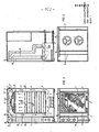
- FIGS. 1 and 5 have rectangular housings which can be closed by means of a door 1.
- the interior of the housing is partitioned with transverse walls 2 in such a way that side channels 3 for air guidance which are approximately equally large are obtained.
- one or more fans 4 with a heating resistor are mounted, which bring the heated air into circulation, the bevelling transverse walls 5 are installed for fluidic reasons.
- the side channels 3 are open at the bottom or laterally with air openings 6 through which the heated air is guided evenly into the brood chamber 7.
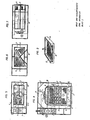
- the trays 8 for the eggs are horizontally displaceable or tiltable as in FIG. 6.
- the bottoms of the trays 8 and the support frame 9 are gas-permeable.
- these can also be gas-impermeable, since the air flow allows this. This is particularly advantageous when the animals hatch.
- a dust filter 10 is arranged in front of the brood chamber 7.
- the humidification takes place via an evaporator dish 11 and / or via a heatable water tank 12, which is flushed with air via channels 16, which lead to the suction and pressure side of the fans 4. In this way, the desired humidity is achieved according to the water temperature.
- Fig. 9 shows a hatching tray, which is raised laterally and divided with transparent transverse walls. The hatched animals remain separated from each other.
Landscapes
- Life Sciences & Earth Sciences (AREA)
- Environmental Sciences (AREA)
- Animal Husbandry (AREA)
- Biodiversity & Conservation Biology (AREA)
- Accommodation For Nursing Or Treatment Tables (AREA)
- Housing For Livestock And Birds (AREA)
Abstract
Description
Die Erfindung betrifft ein Brut- und Schlupfgerät für das Bebrüten von Eiern beliebiger Arten bis zum Schlüpfen.The invention relates to a hatching and hatching device for hatching eggs of any kind until hatching.
Es sind Geräte in verschiedenen Arten und Ausführungen bekannt. Vorliegende Erfindung lag die Aufgabe zu Grunde auch hochempfindliches Eigut mit äußerster exakter Temperatur und Luftfeuchte zu bebrüten um die Ergebnisse von Naturbrut zu übertreffen, dabei war es wesentliche Aufgabe, daß die Bedingungen im gesamten Brutraum eingehalten werden, d. h. daß Temperaturabweichungen unter 0,3° C liegen. Ein weiteres Merkmal ist, zu verhindern, daß der beim Schlupf der Tiere anfallende Staub nicht im ganzen Gerät verteilt wird. Alle bekannten Geräte weisen hier Schwachstellen auf.Devices of various types and designs are known. The present invention was based on the object of also incubating highly sensitive property with extremely exact temperature and air humidity in order to exceed the results of natural brood, it was an essential task that the conditions were observed in the entire brood space, i.e. H. that temperature deviations are below 0.3 ° C. Another feature is to prevent the dust accumulating when the animals hatch from being distributed throughout the device. All known devices have weak points here.
Diese Aufgabe wird durch ein Brut- und Schlupfgerät gemäß dem kennzeichnenden Teil des Anspruches 1 gelöst.This object is achieved by a hatching and hatching device according to the characterizing part of
Erfindungsgemäße Brut- und Schlupfgeräte haben ein im wesentlichen rechteckförmiges oder quadratisches Gehäuse, in welchem eine oder mehrere Bruthorden im entsprechenden oder verstellbarem Abstand übereinanderliegend angeordnet sind, vorteilhaft dabei ist, daß ein oder mehrere Ventilatoren mit Heizquellen so angeordnet sind, daß der Luftweg nach allen Richtungen annähernd gleichmäßig groß ist. Ebenfalls muß die Luft vorteilhaft so zwangsgeführt werden, daß diese in gleichmäßiger Geschwiridigkeit, Menge und Temperatur das Eigut umstreicht. Dies wird je nach Brutraumhöhe und Größe vertikal oder horizontal erreicht. Horizontal = Vorteilhaft bei Bruträumen unter 40 cm Höhe, hier wird der thermische Auftrieb noch nicht so stark wirksam, daß aus diesem Grund Temperaturunterschiede auftreten.Breeding and hatching devices according to the invention have a substantially rectangular or square housing, in which one or more brood trays are arranged one above the other at the appropriate or adjustable distance, it is advantageous that one or more fans with heating sources are arranged so that the airway in all directions is approximately equally large. Likewise, the air must advantageously be guided in such a way that it sweeps around the material in uniform speed, quantity and temperature. This is achieved vertically or horizontally depending on the height and size of the brood. Horizontal = advantageous for hatching rooms below 40 cm in height, here the thermal buoyancy is not yet so effective that temperature differences occur for this reason.
Bei größeren Höhen werden der oder die Ventilatoren vorteilhaft oben zentral angeordnet und die Luft zwangsmäßig beidseitig in gleichgroßen Kanälen nach unten gedrückt um durch die mit gasdurchlässigen Böden ausgestatteten Eihorden gleichmäßig nach oben zu strömen. Beim Schlüpfen der Tiere wird feiner Staub vermischt mit Hährchen frei, damit dieses nicht im ganzen Gerät verteilt wird, ist auf der Saugseite der Ventilatoren ein Filter angeordnet. Dieser bewirkt gleichzeitig einen kleinen Unterdruck im Raum zwischen Filter und Ventilator. In diesem Raum führen Anschlüsse für die Befeuchtung und für Frischluft, weitere Anschlüsse befinden sich auf der Druckseite der oder des Ventilators, so daß speziell die Luftbefeuchtung hierdurch positiv beeinflußt wird, d.h. es werden hier bei Wassertemperaturen unter 50° C über 80 % Luftfeuchtigkeit, bei ca. 37,8° C Lufttemperatur erreicht. Durch die vorteilhafte Führung der Zuluft in den Bereich zwischen Filter und Ventilator wird eine gleichmäßige Verteilung der Frischluft und auch bei Auskühlphasen ein gleichmäßig kühler Luftstrom erreicht. Ausbildung der Brut- und Schlupfhorden mit gasdurchlässigem Boden sind im wesentlichen bekannt, ebenfalls kann eine automatische Wendeeinrichtung wie in unserer Patentanmeldung P 32 43600.9 beschrieben, eingebaut sein. Auch können die Horden so angeordnet sein, daß sich diese jeweils nach links oder rechts kippen lassen, dieses Kippen kann von Hand oder durch Motor erfolgen. Kippen und Wenden der Eier ist notwendig um ein Ankleben des Embrios im Eiinneren zu verhindern.At higher altitudes, the fan or fans are advantageously arranged centrally at the top and the air is forced downward on both sides in channels of equal size in order to flow evenly upwards through the egg trays equipped with gas-permeable floors. When the animals hatch, fine dust is mixed with the spikelets so that it is not distributed throughout the device, a filter is arranged on the suction side of the fans. At the same time, this creates a small negative pressure in the space between the filter and fan. Connections for humidification and fresh air lead in this room, further connections are on the pressure side of the or the fan, so that especially the air humidification is positively influenced, i.e. it is reached here at water temperatures below 50 ° C above 80% air humidity, at an air temperature of approx. 37.8 ° C. Due to the advantageous routing of the supply air into the area between the filter and the fan, a uniform distribution of the fresh air and an evenly cool air flow is achieved even during cooling phases. The formation of hatching and hatching trays with gas-permeable soil is essentially known, and an automatic turning device as described in our patent application P 32 43600.9 can also be installed. The trays can also be arranged so that they can be tilted to the left or right, this tilting can be done by hand or by motor. Tilting and turning the eggs is necessary to prevent the embrios from sticking to the inside of the egg.
Ausführungsbeispiele der Erfindung sind in folgendem anhand der Zeichnungen 1 und 2 näher beschrieben, in diesen zeigen:
- Fig. 1 Vordersicht im Schnitt durch ein Brut-und Aufzuchtgerät mit vertikaler Luftführung,
- Fig. 2 Seitenansicht nach Schnitt AB,
- Fig. 3 Querschnitt durch dieses Brut- und Aufzuchtgerät nach Schnitt CD,
- Fig. 4 Querschnitt nach Schnitt E - F,
- Fig. 5 die Vordersicht eines Brut- und Schlupfgerätes mit horizontaler Luftführung und waagerecht liegenden Horden im Schnitt,
- Fig. 6 die Vordersicht derselben Ausführung nach Fig. 5 mit kippbar gelagerter Horde im Schnitt,
- Fig. 7 Seitenansicht im Schnitt nach A und B nach Fig. 5,
- Fig. 8 den Querschnitt durch das Gerät nach Fig. 5 und
- Fig. 9 eine Ansicht einer Schlupfhorde.
- 1 front view in section through a brood and rearing device with vertical air flow,
- 2 side view after section AB,
- 3 cross section through this breeding and rearing device according to section CD,
- 4 cross section according to section E - F,
- 5 shows the front view of a hatching and hatching device with horizontal air guidance and horizontal trays in section,
- 6 shows the front view of the same embodiment according to FIG. 5 with the horde mounted in a tiltable manner, in section,
- 7 side view in section according to A and B of FIG. 5,
- Fig. 8 shows the cross section through the device of FIG. 5 and
- Fig. 9 is a view of a hatching tray.
Die in den Fig. 1 und 5 gezeigten Brut- und Schlupfgeräte haben rechteckförmige Gehäuse, die mittels einer Tür 1 verschließbar sind. Das Innere der Gehäuse ist mit Querwänden 2 so abgeteilt, daß sich ungefähr genau gleichmäßig große Seitenkanäle 3 für die Luftführung ergeben. Zentral und im gleichen Abstand zu den Seitenkanälen hin sind ein oder mehrere Ventilatoren 4 mit Heizwiderstand montiert, welche die erwärmte Luft in den Umlauf bringen, die Abschrägungen bildenden Querwände 5 sind aus strömungstechnischen Gründen eingebaut.The hatching and hatching devices shown in FIGS. 1 and 5 have rectangular housings which can be closed by means of a
Die Seitenkanäle 3 sind je nachdem ob die Luft vertikal oder horizontal geführt wird, unten offen oder seitlich mit Luftöffnungen 6 versehen, durch welche die erwärmte Luft gleichmäßig in den Brutraum 7 geführt wird.Depending on whether the air is guided vertically or horizontally, the
Im Brutraum 7 sind die Horden 8 für die Eier horizontal verschiebbar oder kippbar wie in Fig.6 angeordnet. Die Böden der Horden 8 sowie die Auflagerahmen 9 sind gasdurchlässig ausgebildet. Bei der Ausführung nach Fig. 1, 2, 3, 5 und 8 können, wie in Fig.7 gezeigt, diese auch gasundurchlässig sein, da die Luftführung dies hierbei zuläßt. Dies ist speziell beim Schlupf der Tiere vorteilhaft.In the
Im Brutraum 7 ist je nach Luftführung und Anordnung des Ventilators 4 (oben oder auf der Rückseite) vor demselben ein Staubfilter 10 angeordnet.Depending on the air flow and arrangement of the fan 4 (above or on the rear), a
Die Befeuchtung erfolgt über eine Verdampferschale 11 und/ oder über einen beheizbaren Wassertank 12, welcher über Kanäle 16, die zur Saug- und Druckseite der Ventilatoren 4 führen, mit Luft durchspült werden. So wird entsprechend der Wassertemperatur die gewünschte Luftfeuchtigkeit erreicht.The humidification takes place via an
Fig.9 zeigt eine Schlupfhorde, die seitlich erhöht und mit durchsichtigen Querwänden unterteilt ist. Die ausgeschlüpften Tiere bleiben so voneinander getrennt.Fig. 9 shows a hatching tray, which is raised laterally and divided with transparent transverse walls. The hatched animals remain separated from each other.
Claims (9)
Applications Claiming Priority (2)
| Application Number | Priority Date | Filing Date | Title |
|---|---|---|---|
| DE19833337237 DE3337237A1 (en) | 1983-10-13 | 1983-10-13 | Hatching and hatching devices |
| DE3337237 | 1983-10-13 |
Publications (2)
| Publication Number | Publication Date |
|---|---|
| EP0137511A2 true EP0137511A2 (en) | 1985-04-17 |
| EP0137511A3 EP0137511A3 (en) | 1987-07-15 |
Family
ID=6211728
Family Applications (1)
| Application Number | Title | Priority Date | Filing Date |
|---|---|---|---|
| EP84112287A Withdrawn EP0137511A3 (en) | 1983-10-13 | 1984-10-12 | Incubator |
Country Status (2)
| Country | Link |
|---|---|
| EP (1) | EP0137511A3 (en) |
| DE (1) | DE3337237A1 (en) |
Cited By (1)
| Publication number | Priority date | Publication date | Assignee | Title |
|---|---|---|---|---|
| RU181465U1 (en) * | 2018-04-19 | 2018-07-16 | Федеральное государственное бюджетное образовательное учреждение высшего образования "Петрозаводский государственный университет" | INDIVIDUAL VENTILATION INCUBATOR |
Families Citing this family (1)
| Publication number | Priority date | Publication date | Assignee | Title |
|---|---|---|---|---|
| IN171924B (en) * | 1988-01-19 | 1993-02-06 | Marmon Corp |
Citations (3)
| Publication number | Priority date | Publication date | Assignee | Title |
|---|---|---|---|---|
| FR766368A (en) * | 1933-10-18 | 1934-06-27 | Artificial incubator | |
| US2364722A (en) * | 1941-10-28 | 1944-12-12 | Kazantzeff John Stephen | Incubator |
| FR1339191A (en) * | 1962-11-13 | 1963-10-04 | Couveuses La Nationale | Apparatus known as an incubator for the artificial clutch of eggs, especially game |
-
1983
- 1983-10-13 DE DE19833337237 patent/DE3337237A1/en not_active Withdrawn
-
1984
- 1984-10-12 EP EP84112287A patent/EP0137511A3/en not_active Withdrawn
Patent Citations (3)
| Publication number | Priority date | Publication date | Assignee | Title |
|---|---|---|---|---|
| FR766368A (en) * | 1933-10-18 | 1934-06-27 | Artificial incubator | |
| US2364722A (en) * | 1941-10-28 | 1944-12-12 | Kazantzeff John Stephen | Incubator |
| FR1339191A (en) * | 1962-11-13 | 1963-10-04 | Couveuses La Nationale | Apparatus known as an incubator for the artificial clutch of eggs, especially game |
Cited By (1)
| Publication number | Priority date | Publication date | Assignee | Title |
|---|---|---|---|---|
| RU181465U1 (en) * | 2018-04-19 | 2018-07-16 | Федеральное государственное бюджетное образовательное учреждение высшего образования "Петрозаводский государственный университет" | INDIVIDUAL VENTILATION INCUBATOR |
Also Published As
| Publication number | Publication date |
|---|---|
| DE3337237A1 (en) | 1985-04-25 |
| EP0137511A3 (en) | 1987-07-15 |
Similar Documents
| Publication | Publication Date | Title |
|---|---|---|
| DE69103302T2 (en) | Incubator for infants. | |
| DE1928939C3 (en) | Climatic chamber | |
| DE19534001A1 (en) | Humidifier chamber | |
| DE102005022934A1 (en) | Plants e.g. herbs, fostering controlling cabinet for use in restaurant, has control device to control air heater and light energy producing device to control growth parameters e.g. air temperature, air volume, duration of light production | |
| DE4407407C2 (en) | Method and device for incubating eggs | |
| DE2301247A1 (en) | INCUBATION APPARATUS AND / OR EGG EXCLUSION CHAMBER AND PROCEDURE FOR BREATING EGGS | |
| EP0137511A2 (en) | Incubator | |
| DE3423147A1 (en) | AIR CONDITIONING | |
| DE69024662T2 (en) | DEVICE AND METHOD FOR INCUBING EGGS | |
| EP0134013A2 (en) | Device for treating cheese with air | |
| DE929454C (en) | Incubator | |
| DE3715735C2 (en) | Cage battery for poultry farming | |
| DE8329555U1 (en) | ||
| DE3139998C2 (en) | Fresh keeping device for bread and the like. Food | |
| DE600736C (en) | Incubator with several individual compartments | |
| DE1944539C3 (en) | Greenhouse | |
| DE646789C (en) | Humidifier for radiators | |
| EP0572062B1 (en) | Apparatus for the treatment of agricultural and horticultural products | |
| DE68912813T2 (en) | Method and device for supplying conditioned air. | |
| DE888329C (en) | Apparatus for warming, frying or the like. | |
| DE3506404A1 (en) | Incubator | |
| DE3840782C2 (en) | incubator | |
| DE921238C (en) | Incubator | |
| EP0585319A1 (en) | Plant cultivation chamber | |
| AT223868B (en) | Device for hatching eggs and keeping chicks warm |
Legal Events
| Date | Code | Title | Description |
|---|---|---|---|
| PUAI | Public reference made under article 153(3) epc to a published international application that has entered the european phase |
Free format text: ORIGINAL CODE: 0009012 |
|
| AK | Designated contracting states |
Designated state(s): BE CH DE FR IT LI NL Kind code of ref document: A2 Designated state(s): BE CH DE FR IT LI NL |
|
| RTI1 | Title (correction) | ||
| PUAL | Search report despatched |
Free format text: ORIGINAL CODE: 0009013 |
|
| AK | Designated contracting states |
Kind code of ref document: A3 Designated state(s): BE CH DE FR IT LI NL |
|
| 17P | Request for examination filed |
Effective date: 19880108 |
|
| 17Q | First examination report despatched |
Effective date: 19890706 |
|
| DIN1 | Information on inventor provided before grant (deleted) | ||
| RIN1 | Information on inventor provided before grant (corrected) |
Inventor name: GRUMBACH, EMIL |
|
| RAP1 | Party data changed (applicant data changed or rights of an application transferred) |
Owner name: GRUMBACH BRUTGERAETE GMBH |
|
| STAA | Information on the status of an ep patent application or granted ep patent |
Free format text: STATUS: THE APPLICATION IS DEEMED TO BE WITHDRAWN |
|
| 18D | Application deemed to be withdrawn |
Effective date: 19920501 |