EP0137423B1 - A roofing plate, a proofing strip for a roofing plate, and a method of producing a roofing plate - Google Patents
A roofing plate, a proofing strip for a roofing plate, and a method of producing a roofing plate Download PDFInfo
- Publication number
- EP0137423B1 EP0137423B1 EP84111559A EP84111559A EP0137423B1 EP 0137423 B1 EP0137423 B1 EP 0137423B1 EP 84111559 A EP84111559 A EP 84111559A EP 84111559 A EP84111559 A EP 84111559A EP 0137423 B1 EP0137423 B1 EP 0137423B1
- Authority
- EP
- European Patent Office
- Prior art keywords
- plate
- roofing plate
- roofing
- proofing
- strip
- Prior art date
- Legal status (The legal status is an assumption and is not a legal conclusion. Google has not performed a legal analysis and makes no representation as to the accuracy of the status listed.)
- Expired
Links
- 238000000034 method Methods 0.000 title claims abstract description 23
- 229920002994 synthetic fiber Polymers 0.000 claims abstract description 50
- 239000003292 glue Substances 0.000 claims abstract description 27
- XLYOFNOQVPJJNP-UHFFFAOYSA-N water Substances O XLYOFNOQVPJJNP-UHFFFAOYSA-N 0.000 claims abstract description 21
- 230000004888 barrier function Effects 0.000 claims abstract description 18
- 230000000717 retained effect Effects 0.000 claims abstract description 6
- 239000000428 dust Substances 0.000 claims abstract description 5
- 239000010410 layer Substances 0.000 claims description 27
- 239000000463 material Substances 0.000 claims description 16
- 239000012790 adhesive layer Substances 0.000 claims description 14
- 238000005266 casting Methods 0.000 claims description 7
- 230000000903 blocking effect Effects 0.000 claims description 4
- 239000002344 surface layer Substances 0.000 claims description 3
- 239000004952 Polyamide Substances 0.000 abstract description 4
- 229920002647 polyamide Polymers 0.000 abstract description 4
- 244000144992 flock Species 0.000 abstract description 3
- 239000011324 bead Substances 0.000 description 16
- 238000010276 construction Methods 0.000 description 15
- 238000012360 testing method Methods 0.000 description 13
- 239000002023 wood Substances 0.000 description 10
- 238000004519 manufacturing process Methods 0.000 description 9
- 239000004568 cement Substances 0.000 description 6
- 230000000694 effects Effects 0.000 description 6
- 239000000835 fiber Substances 0.000 description 6
- 239000004033 plastic Substances 0.000 description 6
- 229920003023 plastic Polymers 0.000 description 6
- 239000004927 clay Substances 0.000 description 5
- 239000000945 filler Substances 0.000 description 5
- 230000000149 penetrating effect Effects 0.000 description 5
- 238000001035 drying Methods 0.000 description 4
- 238000005516 engineering process Methods 0.000 description 4
- 238000007600 charging Methods 0.000 description 3
- 239000000203 mixture Substances 0.000 description 3
- 239000000123 paper Substances 0.000 description 3
- 238000012546 transfer Methods 0.000 description 3
- 238000013022 venting Methods 0.000 description 3
- 229920005830 Polyurethane Foam Polymers 0.000 description 2
- 238000012356 Product development Methods 0.000 description 2
- 230000002745 absorbent Effects 0.000 description 2
- 239000002250 absorbent Substances 0.000 description 2
- 230000001419 dependent effect Effects 0.000 description 2
- 239000011888 foil Substances 0.000 description 2
- 230000002209 hydrophobic effect Effects 0.000 description 2
- 239000002184 metal Substances 0.000 description 2
- 229910052751 metal Inorganic materials 0.000 description 2
- 239000011496 polyurethane foam Substances 0.000 description 2
- 239000004677 Nylon Substances 0.000 description 1
- 229910052770 Uranium Inorganic materials 0.000 description 1
- NIXOWILDQLNWCW-UHFFFAOYSA-N acrylic acid group Chemical group C(C=C)(=O)O NIXOWILDQLNWCW-UHFFFAOYSA-N 0.000 description 1
- 239000011230 binding agent Substances 0.000 description 1
- 230000015572 biosynthetic process Effects 0.000 description 1
- 230000000295 complement effect Effects 0.000 description 1
- 238000010586 diagram Methods 0.000 description 1
- 230000009977 dual effect Effects 0.000 description 1
- 238000007786 electrostatic charging Methods 0.000 description 1
- 238000013213 extrapolation Methods 0.000 description 1
- 238000009472 formulation Methods 0.000 description 1
- 230000005484 gravity Effects 0.000 description 1
- 238000005304 joining Methods 0.000 description 1
- 239000004816 latex Substances 0.000 description 1
- 229920000126 latex Polymers 0.000 description 1
- 230000007774 longterm Effects 0.000 description 1
- 229920001778 nylon Polymers 0.000 description 1
- 238000012856 packing Methods 0.000 description 1
- 230000002093 peripheral effect Effects 0.000 description 1
- 229920001296 polysiloxane Polymers 0.000 description 1
- 229920002635 polyurethane Polymers 0.000 description 1
- 239000004814 polyurethane Substances 0.000 description 1
- 239000010454 slate Substances 0.000 description 1
- 239000007787 solid Substances 0.000 description 1
- 238000010998 test method Methods 0.000 description 1
- 230000007704 transition Effects 0.000 description 1
Images


Classifications
-
- E—FIXED CONSTRUCTIONS
- E04—BUILDING
- E04D—ROOF COVERINGS; SKY-LIGHTS; GUTTERS; ROOF-WORKING TOOLS
- E04D1/00—Roof covering by making use of tiles, slates, shingles, or other small roofing elements
- E04D1/36—Devices for sealing the spaces or joints between roof-covering elements
-
- B—PERFORMING OPERATIONS; TRANSPORTING
- B28—WORKING CEMENT, CLAY, OR STONE
- B28B—SHAPING CLAY OR OTHER CERAMIC COMPOSITIONS; SHAPING SLAG; SHAPING MIXTURES CONTAINING CEMENTITIOUS MATERIAL, e.g. PLASTER
- B28B11/00—Apparatus or processes for treating or working the shaped or preshaped articles
- B28B11/04—Apparatus or processes for treating or working the shaped or preshaped articles for coating or applying engobing layers
-
- B—PERFORMING OPERATIONS; TRANSPORTING
- B28—WORKING CEMENT, CLAY, OR STONE
- B28B—SHAPING CLAY OR OTHER CERAMIC COMPOSITIONS; SHAPING SLAG; SHAPING MIXTURES CONTAINING CEMENTITIOUS MATERIAL, e.g. PLASTER
- B28B19/00—Machines or methods for applying the material to surfaces to form a permanent layer thereon
-
- B—PERFORMING OPERATIONS; TRANSPORTING
- B28—WORKING CEMENT, CLAY, OR STONE
- B28B—SHAPING CLAY OR OTHER CERAMIC COMPOSITIONS; SHAPING SLAG; SHAPING MIXTURES CONTAINING CEMENTITIOUS MATERIAL, e.g. PLASTER
- B28B5/00—Producing shaped articles from the material in moulds or on moulding surfaces, carried or formed by, in or on conveyors irrespective of the manner of shaping
- B28B5/04—Producing shaped articles from the material in moulds or on moulding surfaces, carried or formed by, in or on conveyors irrespective of the manner of shaping in moulds moved in succession past one or more shaping stations
-
- E—FIXED CONSTRUCTIONS
- E04—BUILDING
- E04D—ROOF COVERINGS; SKY-LIGHTS; GUTTERS; ROOF-WORKING TOOLS
- E04D1/00—Roof covering by making use of tiles, slates, shingles, or other small roofing elements
- E04D1/02—Grooved or vaulted roofing elements
- E04D1/04—Grooved or vaulted roofing elements of ceramics, glass or concrete, with or without reinforcement
-
- E—FIXED CONSTRUCTIONS
- E04—BUILDING
- E04D—ROOF COVERINGS; SKY-LIGHTS; GUTTERS; ROOF-WORKING TOOLS
- E04D1/00—Roof covering by making use of tiles, slates, shingles, or other small roofing elements
- E04D1/29—Means for connecting or fastening adjacent roofing elements
- E04D1/2907—Means for connecting or fastening adjacent roofing elements by interfitted sections
- E04D1/2914—Means for connecting or fastening adjacent roofing elements by interfitted sections having fastening means or anchors at juncture of adjacent roofing elements
- E04D1/2916—Means for connecting or fastening adjacent roofing elements by interfitted sections having fastening means or anchors at juncture of adjacent roofing elements the fastening means taking hold directly on adjacent elements of the same row
Definitions
- the present invention relates to a roofing plate, a proofing strip in connection with a roofing plate and a method for producing a roofing plate according to the generic clauses of the claims 1, 9 and 12.
- roofing plates e.g. plates of metal, plastics, slate, fibrous cement or a similar material or tiles; particularly tiles made from concrete, clay or fibrous cement, on a roof construction made from rafters, especially wood rafters, the roofing plates being arranged in an overlapping relationship in such a way that one roofing plate overlaps an adjacent roofing plate.
- the roof construction on which the roofing plates are mounted has a pitch so that the roofing plates are arranged in such a way that one roofing plate overlaps a lower roofing plate. By this pitch snow and water do not collect on the upper surface of the roofing plates, but run down the sloping roof surfaces of the roof construction owing to the effect of gravity.
- the transitions between the individual roofing plates of the roof have most often been proofed by pointing, e.g. by putty or filler material, particularly a foamed filler material, e.g. polyurethane foam, being mounted in the gaps between the roofing plates from the inside of the loft under the roof.
- proofing strips for proofing the gaps between the individual roofing plates of the roof, as well as to mount a so-called roofing underlay, e.g. of cardboard or plastic material, under the roof rafters to produce a substantially hermetic seal of the loft in relation to the environment.
- a roofing plate and a proofing strip according to the generic clauses of the claims 1 and 9 are known from the DE-A-2616919 document.
- This known proofing strip provides a barrier permitting the passage of air from the inside of the loft and out from the outside and into the loft and further permitting the passage of water from the inside of the loft and out and blocking the passage of water and dust from the outside and into the loft.
- An elastic and absorbent proofing strip would, however, absorb water passing from the inside of the loft and out and if a pressure difference occurs due to pressure on the outside of the roof and due to low pressure in the loft the water absorbed by the elastic and absorbent proofing strip is forced back into the loft.
- the roofing plate according to the invention eliminates the use of separate venting ducts which, as mentioned above, have proved not to be sufficiently efficient, and at the same time eliminates the risk of rot or dry rot attacks on the wood construction of the roof as a result of the barrier forming effect of the proofing strip, formed by the upright synthetic fibres.
- the mounting of the roofing plate of the invention on a roof further eliminates the necessity of establishing a roofing underlay or of subsequent pointing such as has hitherto been necessary particularly in connection with tiled roofs.
- the synthetic fibres may have a free length of about 1-30 mm, preferably about 2-15 mm, more preferably 3-8 mm.
- the synthetic fibres may have a thickness of about 0.01-0.5 mm, preferably about 0.05 mm.
- the characteristics of the synthetic fibres are specified in the units of dtex, i.e. the weight in grams of a predetermined length, e.g. 10.000 m, of the fibre is specified.
- the fibre thickness and the fibre length must be adapted to each other in such a way that the resulting synthetic fibre has sufficient mechanical strength to provide a mechanically stable proofing strip.
- the synthetic fibres thereof may form a maze pattern.
- the proofing strip may be composed of fibres of different lengths and/or of different thicknesses.
- the roofing plate is of a substantially rectangular configuration having pairs of opposite edges constituting vertical and horizontal edges of the plate when the plate is arranged on the roof.
- the proofing strip may extend along one of the horizontal edges of the plate.
- the proofing strip is arranged on the side surface of the plate constituting the upper side surface when the plate is arranged on the roof.
- the proofing strip may be arranged on the side surface of the plate constituting the lower side surface when the plate is arranged on the roof.
- a further proofing strip arranged extending along one of the said vertical edges of the plate of a substantially rectangular configuration may further provided proofing between any two roofing plates arranged horizontally beside each other on the roof.
- the further proofing strip may be arranged on the upper side surface or, alternatively, on the lower side surface of the roofing plate fulfilling the proofing requirements in accordance with the teaching of the present invention, it is, however, from a productional point of view, preferred to provide the proofing strip extending along said horizontal edge of the plate and the further proofing strip extending along one of said vertical edges of the plate on the same upper or, alternatively, lower side surface of the plate, as the proofing strips may be arranged on the roofing plate without providing access to more than one of the side surfaces of the roofing plate, e.g. without turning the roofing plate upside down.
- a first proofing strip may be arranged on said upper side surface of the plate at the uppermost horizontal edge thereof, and the second proofing strip may be arranged on said lower sidesurface of the plate at the lowermost horizontal edge thereof.
- the invention is directed to a method of producing a roofing plate, said roofing plate being cast in a mould or form. Such a method is disclosed in . DE-A-1759427.
- the inventive method is characterized in that the proofing strip is arranged in a groove in said mould or form before it is filled for casting the roofing plate.
- the synthetic fibres may be transferred to the roofing plate in a simple mechanical way, e.g. by so-called vibration application.
- the synthetic fibres are transferred to the adhesive layer in an electrostatically charged state of a high potential, and the adhesive layer is maintained at a polarity opposite to the polarity of the fibres.
- the electrostatic charging of the fibres causes them to repel against each other electrostatically, and consequently the fibres will arrange themselves standing substantially upright from the adhesive layer of the roofing plate.
- the adhesive layer may be a layer of glue. Consequently, the proofing strip formed by synthetic fibres may be provided on a roofing plate which is precast or prefabricated, the synthetic fibre.s being glued to the roofing plate by means of a layer of glue applied thereto.
- This method may be carried out on a building site, if desired, so that prior to the mounting of the roofing plates on a roof, the roofing plates have a layer of glue applied and then a synthetic fibre proofing strip is applied electrostatically, whereafter the layer of glue is cured.
- the roofing plate is of a curable material, and the synthetic fibres are transferred to the roofing plate before the latter is cured, and are retained in a surface layer of the roofing plate, said layer consituting the adhesive layer.
- the synthetic fibres constituting the proofing strip according to the invention are cast into the material of the roofing plate itself, providing a particularly simple method of production.
- a roofing plate 10 which is a corrugated tile made from concrete, clay or fibrous cement.
- a first side surface is shown, viz. the side surface facing outwards from a roof
- the second side surface is shown, viz. the side surface facing towards a loft defined within or below the roof.
- the corrugated roofing plate or tile 10 is provided with a bead 12 at its lower side surface and at its uppermost edge extending transversely across the corrugations.
- the bead 12 is adapted to catch behind a supporting wood rafter 34, when the roofing plate or tile 10 is mounted on a bearing wood construction.
- the roofing plate 10 has three beads 18, 20 and 22 extending substantially across the corrugations and further two grooves 24 and 26 defined between said three beads and also extending substantially across the corrugations.
- the roofing plate or tile 10 is a so-called interlocking tile, i.e.
- a first proofing strip 27 constituting a proofing strip according to the invention is arranged on the upper side surface of the roofing plate or tile at the uppermost edge thereof and extending across the corrugations of the plate or tile.
- a second proofing strip 29 constituting a further proofing strip according to the invention is arranged and is provided with a proofing strip extension 29a which is arranged at the vertical side surface of the roofing plate or tile at the lowermost edge thereof.
- the proofing strip extension 29a is adapted to cooperate with one or more of the left hand ends of the beads 18, 20 and 22, shown in Fig. 3.
- the proofing strips 27 and 29 and the proofing strip extension 29a are constituted by synthetic fibres, e.g. plastics or nylon fibres, preferably of a thickness of about 0.05 mm (dtex) and of a free length of about 3-8 mm.
- the synthetic fibre proofing strips 27, 29 and the synthetic fibre proofing strip extension 29a are made from a composition of synthetic fibres of a length of 3 mm and of a length of 5 mm.
- the proofing strips 27 and 29 and the proofing strip extension 29a exhibit the unique characteristic that they permit air to pass from the inside of the loft and out and from the outside and into the loft and further permit water to pass from the inside of the loft, but block the passage of water and dust from the outside and into the loft.
- a proofing strip of basically identical construction may, alternatively or fur - ther, be arranged on the central or the innermost bead extending along the corrugations of the roofing plate or tile or in any of the grooves 16 defined between the beads 14.
- the roofing plate ortile 10 shown in Fig. 1 is mounted above and overlapping another roofing plate 32 which is completely identical to the roofing plate 10 and which is arranged in the above described manner having its bead 12 catching behind the roof rafter 34. Furthermore, the roof plate 32 is fastened to the rafter 34 by means of a roof hook 36. As is evident from Fig.
- the proofing strip 27 is clamped between the lower side surface of the roofing plate or tile 10 and the upper side surface of the roofing plate or tile 32 providing the above described venting and blocking characteristics and further providing an optimum venting of the loft below the roof, which further eliminates the risk of rot or dry rot attacks on the wood construction of the roof (the roof rafter 34) caused by the formation of condensed water in the loft.
- a second embodiment of a roofing plate according to the invention is shown.
- This second embodiment differs from the above described first, presently preferred embodiment of the roofing plate according to the invention in that the proofing strips 27 and 29 and the proofing strip extension 29a are omitted.
- a proofing strip 28 is arranged on the lower side surface of the roofing plate or tile 10 in the groove 24 extending transversely across the corrugations of the roofing plate or tile, and a proofing strip 30 is further arranged at the lower side surface of the roofing plate or tile 10 in the central groove 16 extending along the corrugations of the roofing plate or tile.
- a single proofing strip 28 arranged in the groove 24 another or further proofing strip may be arranged in the groove 26 (not shown on the drawing), and alternatively or supplementary, one or more proofing strips may be arranged on one or more of the beads 18, 20 and 22 extending across the corrugations of the roofing plate or tile.
- a further or alternative proofing strips may be arranged in the left-hand and the right-hand grooves 16 and on one or more of the beads 14 in the left-hand side lock of the roofing plate or tile 10.
- Fig. 4 which basically corresponds to Fig. 2, the second embodiment of the roofing plate according to the invention shown in Fig. 3 is shown mounted above and overlapping the above described roofing plate 32 which is completely identical to the roofing plate 10 shown in Fig. 3.
- the proofing strip 28 is clamped between the lower side surface of the roofing plate or tile, viz. the groove 24, and the upper side surface of the roofing plate or tile 32 providing the above described barrier characteristics.
- the proofing strips i.e. the proofing strips 27 and 29 and further the proofing strip extension 29a, and the proofing strips 28 and 30 are of a basically identical configuration.
- the proofing strips may obviously be of a different configuration, i.e. have synthetic fibres of different thickness, length or different compositions of fibres, and furthermore, the proofing strips extending along the corrugations of the roofing plate or tile 10 may alternatively be constituted by a proofing strip of a different type and/or of a different material, e.g. an elastic and completely humidity-impermeable proofing material, such as a massive latex strip impregnated with silicone.
- Fig. 5 an alternative or combined embodiment of the above described first and second embodiments of the roofing plate according to the invention is shown.
- the roofing plates or tiles 10 and 32 are each provided with a total of four proofing strips, viz. the above described proofing strips 27-30 which cooperate in pairs so that the proofing strips extending across the corrugations of the roofing plates or tiles, i.e. the proofing strips 27 and 28, cooperate, and so that the proofing strips extending along the corrugations of the roofing plates or tiles, i.e. the proofing strips 29 and-30, or the above mentioned proofing strips in cooperating grooves and beads of the interlock, cooperate with each other.
- These cooperating proofing strips may provide a burr-like locking.
- FIG. 6 and 7 vertical sectional views basically corresponding to the vertical sectional views of Figs. 2, 4 and 5 are shown illustrating a seventh and eighth embodiment of the roofing plate according to the invention.
- the proofing strip 28 shown in Fig. 4 has been replaced by a proofing strip 42 which is cast into the roofing plate 10 in a bead 44 which is broader compared to the bead 18.
- the proofing strip 42 which is produced as a separate unit and then cast into the roofing plate as will be explained below, comprises a base layer 46, e.g. a plastic foil base layer or a gauze strip base layer from which the barrier forming part 48 of the proofing strip 42 protrudes.
- a base layer 46 e.g. a plastic foil base layer or a gauze strip base layer from which the barrier forming part 48 of the proofing strip 42 protrudes.
- the barrier forming part 48 of the proofing strip 42 constitutes a combination of the above embodiments, as this barrier forming part 43 is constituted by upright synthetic fibres like the proofing strips 27-30 of the first and second embodiments of the roofing plate shown in Figs. 1-5, but the synthetic fibres in the barrier forming part 48 form a maze pattern like the knob- shaped bodies 40 in the third, fourth, fifth and sixth embodiments shown in Figs. 6-9.
- a slightly modified eighth embodiment is shown in Fig. 7, in which the proofing strip 42, instead of a gauze strip base layer, has a base body 50 on which the synthetic fibres which form the barrier forming part of the proofing strip, are arranged prior to the casting of the base body 50 into the roofing plate 10.
- Fig. 8 a horizontal sectional view through the above described first, presently preferred embodiment of the roofing plate according to the invention cooperating with the adjacent roofing plate is shown, i.e. a sectional view perpendicular to the sectional view of Fig. 2.
- Fig. 8 the above described dual length proofing strips 27 and 29 are shown providing the proofing and barrier characteristics in accordance with the teaching of the present invention.
- Figs. 9 and 10 horizontal sectional views basically corresponding to the above described sectional view of Fig. 8 are shown.
- Fig. 13 an embodiment of the roofing plate according to the invention is shown basically of the construction shown in Figs. 3 and 4.
- the proofing strip 30 extending along the corrugations of the roofing plate or tile and arranged in the central groove 16 is omitted.
- the innermost of the projections 14 of the roofing plate 10 is provided with a proofing strip 52 constituting a separate unit which is arranged on the roofing plate 10 prior to the arrangement of the roofing plate in the above described overlapping relationship with the adjacent roofing plate 32.
- the proofing strip 52 has a base layer 54, which is preferably a plastic foil or a gauze strip, and a proofing strip forming part 56.
- the part 56 may be constituted by synthetic fibres or instead be a hydrophobic elastic mass.
- the base layer 54 has a glue protected by a slip paper which is removed before the proofing strip is arranged on the roofing plate 10, and apart from the base layer 54 shown in Fig. 9 the proofing strip 52 may be provided with a further base layer arranged opposite to the base layer 54 and adapted to adhere to the roofing plate 32 within the groove 16.
- the proofing strip 30 shown in Fig. 3 has been replaced by a separate proofing strip 52 to be arranged on the roofing plate 10 prior to the arrangement of the roofing plate 10 in the overlapping relationship with the roofing plate 32
- the proofing strip 28 shown in Figs. 3, 4 and 5 may be replaced by a separate proofing strip which is also arranged on one of the projections 18, 20 and 22 or in one of the grooves 24 or 26 prior to the arrangement of the roofing plate 10 in the overlapping relationship with the roofing plate 32.
- This separate proofing strip in replacement of the proofing strip 28 shown in Figs. 3, and 5 may also on both sides have a base layer and a glue layer, preferably protected by removable or tearable slip paper or slip papers to be removed as explained above prior to the arrangement of the strips on the roofing plate or tile, for making the proofing strip adhere to the lower side surface of the roofing plate or tile 10 and to the upper side surface of the roofing plate or tile 32.
- a sectional view basically corresponding to the sectional view shown in Fig. 9 is shown through an embodiment slightly modified in relation to the fifth embodiment of the roofing plate according to the invention shown in Fig. 8.
- the roofing plate 32 thus, instead of two grooves 16, has a single broader groove 58 in which two proofing strips 60 and 62 are arranged.
- the proofing strips 60 and 62 may be constructed in accordance with the teaching of the present invention, e.g. be of any of the above described types, i.e. they may be constituted by upright synthetic fibres or be made from an elastic, hydrophobic material forming a maze pattern.
- Figs. 11 and 12 diagrammatically show plants for producing roofing plates corresponding to the above embodiments in accordance with the methods of the present invention.
- the plant shown in Fig. 11 comprises a number of stations A-I through which a mould or form 72 is passed by means of continuously operating conveyor means 70.
- the mould or form 72 which has a shape complementary to the desired roofing plate shape, is cleaned.
- proofing strips 74 and 76 are arranged in grooves in the mould or form 72.
- Station C serves to transport the mould or form with the proofing strips 74 and 76 arranged in it on to a station D in which the mould or form is filled with casting material, which may be e.g. concrete, clay or fibrous cement.
- casting material which may be e.g. concrete, clay or fibrous cement.
- the mould or form having proofing strips arranged in it and casting material arranged on it is passed via a station E to a station F in which the casting material is cured.
- the roofing plate which is substantially finished is passed via a station G to a station H, in which the mould or form 72 is separated from the finished roofing plate 10.
- station I the finished roofing plate 10 is passed to a store, while the mould or form 72 is returned to the station A, whereupon the above production process is repeated.
- the proofing strips 74 and 76 are cast into the roofing plate 10 in accordance with the method of producing roofing plates described above with reference to Fig. 15.
- the plant in Fig. 12 differs from the plant shown in Fig. 11 in that the proofing strips of the roofing plate are not applied to or arranged on the roofing plate until after the latter has been produced and is substantially finished.
- the roofing plate 10 is passed to a station K in which the area of the upper side surface the lower side surface of the roofing plate on which proofing strips are to be applied, are cleaned, and a binder in the form of an adhesive layer or glue layer is applied.
- the roofing plate 10 is passed to a station L in which the proofing strips of the roofing plate 10 are applied. While the proofing strips 74 and 76 described above with reference to Fig. 11 may be of any of the above types, preferably, however, comprising a base layer corresponding to the embodiments shown in Figs. 6 and 11, a strip of synthetic fibres constituting the proofing strip according to the invention is applied directly to the roofing plate or tile 10 in station L.
- the synthetic fibres are passed from a reservoir 78 to a charging chamber 80 in which the fibres are charged electrostatically to a negative polarity and from which the fibres may only escape through a nozzle 82.
- the roofing plate 10 is passed over the charging chamber 80 and the nozzle 82. As shown in Fig.
- a positive pole plate 84 attracting the fibres electrostatically charged to negative polarity is arranged on the side of the roofing plate 10 opposite to the fibre reservoir 78 and the charging chamber 80.
- the electrostatic fibres leave the nozzle 82 at great speed and are retained in the adhesive layer or glue layer applied in station K. In a station M, the excess fibres are cleaned off.
- the synthetic fibres may be charged to a positive polarity, the pole plate 84 then being maintained at negative polarity.
- the electrostatical application station L may be turned upside down so that the fibres are applied from a nozzle above the roofing plate or tile. Consequently, the roofing plate or tile has its side surface to be provided with the synthetic fibre proofing strips facing upwards instead of downwards as in the embodiment shown in Fig. 12. Furthermore, the station M serving the purpose of removing excess fibres may advantageously be modified into a suction station.
- the plant shown in Fig. 12 may, in accordance with the invention, be modified by the roofing plate 10 shown in the station J being a cast by as yet unhardened roofing plate or tile of e.g. clay, concrete or fibrous cement.
- the synthetic fibres are retained directly in the surface of the still wet and unhardened roofing plate or tile 10. Consequently, the use of an adhesive layer or glue layer to be applied in the station K may be avoided.
- a conveyor 100 receives the roofing plates or tiles to be provided with proofing strips in accordance with the teaching of the present invention or to be transferred to a store as indicated by an arrow at the right hand end of the conveyor 100.
- the conveyor 100 cooperates with a transfer station 102 in which the roofing plates or tiles are transferred from the conveyor 100 to four parallel conveyors 103, 104, 105 and 106 and if necessary turned upside down so that the upper side surfaces of the roofing plates or tiles 10 to be applied with proofing strips are facing upwards.
- the conveyors 103, 104, 105 and 106 make the roofing plates or tiles advance at a speed of approximately ten roofing plates or tiles per minute on each of the conveyors providing a total production speed or capacity of approximately forty roofing plates or tiles per minute.
- the roofing plates or tiles are advanced intermittently by means of the conveyors 103-106 in a direction indicated by an arrow 120 and are transferred to the glue application station K in which two glue applicators 108 and 110 apply glue to the areas of the upper side surfaces of the roofing plates or tiles to have the proofing strips 27 and 29 and the proofing strip extension 29a shown in Fig. 1 arranged thereon while the roofing plates or tiles are intermittantly stopped below the glue applicators 108 and 110.
- the glue applicators 108 and 110 apply layers of water- based and acrylic basis glue and of a thickness corresponding to a glue consumption of 300-500 g/m 2 .
- the roofing plates or tiles 10 are transferred from the intermittantly operated conveyors 103, 104, 105 and 106 to continuously operated conveyors 111, 112, 113 and 114, respectively.
- the conveyors 111-114 are moving continuously at a speed of approximately 4-5 m/min. They serve the purpose of moving the preglued roofing plates or tiles to the synthetic fibre application station L and to a glue drying station N.
- the synthetic fibre application station L is divided into two substations designated L1 and L2, respectively.
- the substations L1 and L2 serve the purpose of applying synthetic fibres of a length of 3 mm and 5 mm, respectively, to the preglued roofing plates or tiles.
- the synthetic fibres are preferably of polyamide of the type 22 dtex and are pretreated for electrostatical application.
- synthetic fibres are charged to a potential of approximately 50-100 kV of negative polarity relative to earth and the roofing plates or tiles are maintained at opposite, i.e. positive polarity.
- Each of the synthetic fibre application stations L1 and L2 comprise two parallel applicators 116, 117 and 122, 123, respectively, constituted by vacuum suction devices which are connected to the applicators 116, 117 and 122, 123, respectively, through return conduits 119 and 125, respectively.
- the roofing plates or tiles 10 having the synthetic fibres arranged standing upright from the outer side surfaces thereof and adhering in the glue layers are transferred to the glue drying station N comprising infra-red radiators 128 and 129.
- the glue layers of the roofing plates or tiles are cured so that the synthetic fibres arranged standing upright therefrom are fastened to the roofing plates or tiles.
- the finished roofing plates or tiles are transferred to a further conveyor 130 by means of which the finished roofing plates or tiles are transferred to the above mentioned store as indicated by an arrow at the lower end of the conveyor 130.
- the conveyor 130 may transfer the finished roofing plates or tiles to a packing station O shown in the lower right-hand side of Fig. 12.
- the width of the proofing strip extending across the corrugations at the uppermost end of the tile, i.e. the proofing strip corresponding to the proofing strip 27 shown in Fig. 1 was 25 mm.
- a two component polyurethane basis glue was applied manually to the upper side surface of the roofing plate or tile providing a layer of glue of a thickness of approximately 0.5 mm.
- the proofing strips were constituted by a combination of 3 mm and 5 mm, 22 dtex polyamide fibres which had been pretreated for electrostatic application (pretreated for Flock application).
- the polyamide fibres were applied to the upper side surface of the tile by means of a test laboratory Flock application apparatus, and thereafter, the glue was cured.
- the overlap of the tiles was 75 mm, and the tiles were not nailed to the supporting roof construction.
- the roof construction defined a pitch of 30° in relation to the horizon and exposed the outer side surface of the test group set-up to wind and rain generated by wind and rain generators.
- the wind speed was 13.4 m/s and the rain fall rate was 38 mm/h.
- a perspect box was arranged below the test group set-up. By reducing the pressure within the perspect box, i.e. at the lower side surface of the test group set-up, a kind of suction effect was produced resulting in an increase in the amount of water penetrating through the tile construction to the lower side surface thereof.
- the lower side surface pressure was reduced in increments of 10 Pa and the amount of water penetrating through the tile construction during a 5 min. period was measured.
- the measuring results were converted into an amount per hour and a graph was plotted illustrating the amount of water penetrating through the tile construction as a function of the reduced pressure at the lower side surface of the test group set-up.
- a first curve designated S illustrates the response obtained with regard to the tiles without proofing strips
- a second curve designated V illustrates the measuring results obtained with regard to the roofing plates according to the invention, i.e. the tiles with proofing strips.
- These measuring results were obtained at a rig pitch of 30°.
- a further curve T was obtained.
- a fourth curve designated U is an extrapolation of the initial measuring results obtained with regard to the tiles with proofing strips and is a compensation of the discontinuity of the V curve. This discontinuity is believed to be caused by a "slug" effect, i.e. the water penetrating to the lower side surface of the tiles is not dripping but creeping down the lower side surface of the tiles, and is consequently not measured.
- roofing plates which are not corrugated, e.g. plates of metal, plastics or a similar material
- synthetic fibres of the proofing strip may advantageously, as mentioned above, form a maze pattern to further increase the barrier forming effect.
Landscapes
- Engineering & Computer Science (AREA)
- Structural Engineering (AREA)
- Chemical & Material Sciences (AREA)
- Ceramic Engineering (AREA)
- Architecture (AREA)
- Civil Engineering (AREA)
- Mechanical Engineering (AREA)
- Manufacturing & Machinery (AREA)
- Roof Covering Using Slabs Or Stiff Sheets (AREA)
- Laminated Bodies (AREA)
- Building Environments (AREA)
- Aftertreatments Of Artificial And Natural Stones (AREA)
- Conveying And Assembling Of Building Elements In Situ (AREA)
- Buffer Packaging (AREA)
- Gasket Seals (AREA)
- Seal Device For Vehicle (AREA)
- Application Of Or Painting With Fluid Materials (AREA)
- Hybrid Cells (AREA)
- Nonwoven Fabrics (AREA)
- Catalysts (AREA)
- Diaphragms For Electromechanical Transducers (AREA)
- Insulating Bodies (AREA)
- Sealing Battery Cases Or Jackets (AREA)
- Lining Or Joining Of Plastics Or The Like (AREA)
- Camera Bodies And Camera Details Or Accessories (AREA)
- Body Structure For Vehicles (AREA)
Abstract
Description
- The present invention relates to a roofing plate, a proofing strip in connection with a roofing plate and a method for producing a roofing plate according to the generic clauses of the
claims - It is generally known to mount roofing plates, e.g. plates of metal, plastics, slate, fibrous cement or a similar material or tiles; particularly tiles made from concrete, clay or fibrous cement, on a roof construction made from rafters, especially wood rafters, the roofing plates being arranged in an overlapping relationship in such a way that one roofing plate overlaps an adjacent roofing plate. Normally, the roof construction on which the roofing plates are mounted, has a pitch so that the roofing plates are arranged in such a way that one roofing plate overlaps a lower roofing plate. By this pitch snow and water do not collect on the upper surface of the roofing plates, but run down the sloping roof surfaces of the roof construction owing to the effect of gravity.
- Hitherto, in connection with tiled roofs, i.e. roofs made from tiles of concrete, clay or fibrous cement, the transitions between the individual roofing plates of the roof have most often been proofed by pointing, e.g. by putty or filler material, particularly a foamed filler material, e.g. polyurethane foam, being mounted in the gaps between the roofing plates from the inside of the loft under the roof. It is further known to use proofing strips for proofing the gaps between the individual roofing plates of the roof, as well as to mount a so-called roofing underlay, e.g. of cardboard or plastic material, under the roof rafters to produce a substantially hermetic seal of the loft in relation to the environment.
- These known roof proofing methods, however, suffer from a number of disadvantages. Thus, pointing of a tiled roof is both a difficult and time consuming operation, and particularly when foamed filler material, e.g. polyurethane foam, is used as disclosed in DE-A-1759427, the connection between the individual roofing plates of the roof tends to give leaks after a fairly short time, primarily due to the influence of frost and thaw. It has also proved difficult to establish a weatherproof connection with long term stability between roofing plates by the use of known proofing strips.
- A roofing plate and a proofing strip according to the generic clauses of the
claims 1 and 9 are known from the DE-A-2616919 document. This known proofing strip provides a barrier permitting the passage of air from the inside of the loft and out from the outside and into the loft and further permitting the passage of water from the inside of the loft and out and blocking the passage of water and dust from the outside and into the loft. An elastic and absorbent proofing strip would, however, absorb water passing from the inside of the loft and out and if a pressure difference occurs due to pressure on the outside of the roof and due to low pressure in the loft the water absorbed by the elastic and absorbent proofing strip is forced back into the loft. - From the FR-A-2296062 document a method for assembling building elements, by locking the elements together is known. Bar-like locking components are used constituted by upright synthetic fibres applied to the building elements at their peripheral rim portions and by subsequently joining the elements together by means of a filler. By applying a filler the overall structure is sealed hermetically.
- It is the object of the present invention to provide a roofing plate and a proofing strip which renders possible labour-saving mounting of roofing plates as well as eliminating the above disadvantages with regard to the formulation of condensed water and any consequent rot or dry rot attacks on wood construction of the roof and which blocks the passage of water from outside and into the loft even at extremely high pressure differences.
- This object is fulfilled by means of a roofing plate and proofing strip in connection with a roofing plate having the features of the
claims 1 and 9 respectively. It was found that by constituting the proofing strip by a strip of upright synthetic fibres said object is fulfilled. - The roofing plate according to the invention, to a great extent, eliminates the use of separate venting ducts which, as mentioned above, have proved not to be sufficiently efficient, and at the same time eliminates the risk of rot or dry rot attacks on the wood construction of the roof as a result of the barrier forming effect of the proofing strip, formed by the upright synthetic fibres. The mounting of the roofing plate of the invention on a roof further eliminates the necessity of establishing a roofing underlay or of subsequent pointing such as has hitherto been necessary particularly in connection with tiled roofs.
- Dependent on the material of the roofing plate and of the free distance between the roofing plates when they are mounted on a roof, the synthetic fibres may have a free length of about 1-30 mm, preferably about 2-15 mm, more preferably 3-8 mm. Dependent on the fibre length the synthetic fibres may have a thickness of about 0.01-0.5 mm, preferably about 0.05 mm. Normally, the characteristics of the synthetic fibres are specified in the units of dtex, i.e. the weight in grams of a predetermined length, e.g. 10.000 m, of the fibre is specified. Obviously the fibre thickness and the fibre length must be adapted to each other in such a way that the resulting synthetic fibre has sufficient mechanical strength to provide a mechanically stable proofing strip. To increase the barrier forming effect of the proofing strip, the synthetic fibres thereof may form a maze pattern. Alternatively, the proofing strip may be composed of fibres of different lengths and/or of different thicknesses.
- Conventionally, the roofing plate is of a substantially rectangular configuration having pairs of opposite edges constituting vertical and horizontal edges of the plate when the plate is arranged on the roof. In order to provide proofing of the loft in relation to the environment in accordance with the principles of the present invention, the proofing strip may extend along one of the horizontal edges of the plate.
- In a first embodiment of the roofing plate of a substantially rectangular configuration and provided with the proofing strip extending along one of the horizontal edges of the plate, the proofing strip is arranged on the side surface of the plate constituting the upper side surface when the plate is arranged on the roof. Alternatively, the proofing strip may be arranged on the side surface of the plate constituting the lower side surface when the plate is arranged on the roof.
- Whereas the above described proofing strip extending along one of the horizontal edges of the plate provides proofing between a roofing plate and another roofing plate arranged below or above the first mentioned roofing plate in the above described overlapping relationship, a further proofing strip arranged extending along one of the said vertical edges of the plate of a substantially rectangular configuration may further provided proofing between any two roofing plates arranged horizontally beside each other on the roof. Although the further proofing strip may be arranged on the upper side surface or, alternatively, on the lower side surface of the roofing plate fulfilling the proofing requirements in accordance with the teaching of the present invention, it is, however, from a productional point of view, preferred to provide the proofing strip extending along said horizontal edge of the plate and the further proofing strip extending along one of said vertical edges of the plate on the same upper or, alternatively, lower side surface of the plate, as the proofing strips may be arranged on the roofing plate without providing access to more than one of the side surfaces of the roofing plate, e.g. without turning the roofing plate upside down.
- In an alternative embodiment of the roofing plate of a substantially rectangular configuration, a first proofing strip may be arranged on said upper side surface of the plate at the uppermost horizontal edge thereof, and the second proofing strip may be arranged on said lower sidesurface of the plate at the lowermost horizontal edge thereof. Although this embodiment of the invention provides proofing in accordance with the teaching of the present invention, it suffers from the above described productional drawback, viz. that proofing strips have to be arranged on opposite side surfaces of the roofing plate comprising a number of production steps involving the provision of access from both side surfaces or turning the roofing plate upside down.
- The invention is directed to a method of producing a roofing plate, said roofing plate being cast in a mould or form. Such a method is disclosed in . DE-A-1759427. The inventive method is characterized in that the proofing strip is arranged in a groove in said mould or form before it is filled for casting the roofing plate.
- When this method according to the invention is employed, the synthetic fibres may be transferred to the roofing plate in a simple mechanical way, e.g. by so-called vibration application. In accordance with a particular embodiment of the method according to the invention, the synthetic fibres are transferred to the adhesive layer in an electrostatically charged state of a high potential, and the adhesive layer is maintained at a polarity opposite to the polarity of the fibres. The electrostatic charging of the fibres causes them to repel against each other electrostatically, and consequently the fibres will arrange themselves standing substantially upright from the adhesive layer of the roofing plate.
- In accordance with this aspect of the method of the present invention, the adhesive layer may be a layer of glue. Consequently, the proofing strip formed by synthetic fibres may be provided on a roofing plate which is precast or prefabricated, the synthetic fibre.s being glued to the roofing plate by means of a layer of glue applied thereto. This method may be carried out on a building site, if desired, so that prior to the mounting of the roofing plates on a roof, the roofing plates have a layer of glue applied and then a synthetic fibre proofing strip is applied electrostatically, whereafter the layer of glue is cured.
- In accordance with a special embodiment of the method of the invention, the roofing plate is of a curable material, and the synthetic fibres are transferred to the roofing plate before the latter is cured, and are retained in a surface layer of the roofing plate, said layer consituting the adhesive layer. In accordance with this embodiment, the synthetic fibres constituting the proofing strip according to the invention are cast into the material of the roofing plate itself, providing a particularly simple method of production.
- The invention will now be further described with reference to the drawing, wherein
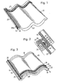
- Fig. 1 is a perspective view of a first, presently preferred embodiment of a roofing plate according to the invention having proofing strips according to the invention arranged on the upper side surface of the roofing plate,
- Fig. 2 a vertical sectional view through the first embodiment of the roofing plate according to the invention shown in Fig. 1 arranged on a corresponding roofing plate mounted on a supporting wood rafter,
- Fig. 3 a perspective view corresponding to Fig. 1 of a second embodiment of a roofing plate according to the invention having proofing strips according to the invention arranged on the lower side surface of the roofing plate
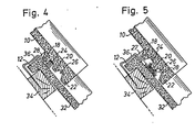
- Fig. 4 a vertical, sectional view corresponding to Fig. 2 through the second embodiment of the roofing plate according to the invention shown in Fig. 3 arranged on a corresponding roofing plate mounted on a supporting wood rafter,
- Fig. 5 a vertical sectional view through a slightly modified embodiment of the first embodiment of the roofing plate shown in Fig. 1 arranged on a corresponding roofing plate mounted on a supporting wood rafter,
- Figs. 6 and 7 vertical, sectional views corresponding to Figs: 2, 4, 5 of alternative embodiments of the second embodiment of the roofing plate shown in Figs. 3 and 4,
- Fig. 8 a sectional view at right angles to the vertical sectional view of Fig. 2,
- Fig. 9 a sectional view corresponding to Fig. 3 through the second embodiment of the roofing plate shown in Figs. 3 and 4,
- Fig. 10 a sectional view corresponding to Figs. 8 and 9 through the fifth embodiment of the roofing plate according to the invention shown in Fig. 8.
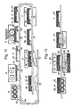
- Figs. 11 and 12 schematical views illustrating production plants, for carrying out methods of producing roofing plates according to the invention in accordance with the teaching of the present invention.
- Fig. 13 a schematical top view of a production plant presently constituting the preferred embodiment for carrying out the presently preferred embodiment of the method of producing roofing plates according to the invention, and
- Fig. 14 a diagram illustrating proofing characteristics of a conventional roofing plate and of the roofing plate according to the invention shown in Figs. 1 and 2.
- In Figs. 1, 2, 3, 4 and 5, a
roofing plate 10 is shown which is a corrugated tile made from concrete, clay or fibrous cement. In Fig. 1, a first side surface is shown, viz. the side surface facing outwards from a roof, whereas in Fig. 3, the second side surface is shown, viz. the side surface facing towards a loft defined within or below the roof. It is to be understood that the terms indicating directions, such as upper, lower, vertical, horizontal, etc. used in the present context, refer to the conventional orientation of the roofing plates or tiles when mounted on a roof supporting wood construction of a predetermined pitch. As is evident from Fig. 3, the corrugated roofing plate ortile 10 is provided with abead 12 at its lower side surface and at its uppermost edge extending transversely across the corrugations. As is evident from Figs. 2, 4 and 5 thebead 12 is adapted to catch behind a supportingwood rafter 34, when the roofing plate ortile 10 is mounted on a bearing wood construction. At its lower side surface, and at the lowermost edge thereof, and opposite thebead 12, theroofing plate 10 has threebeads grooves tile 10 is a so-called interlocking tile, i.e. it is provided withprojections 14 andgrooves 16 extending at the vertical outer edges of the tile along with the corrugations thereof which are adapted to cooperate with corresponding grooves and projections, respectively, of an adjacent roofing plate or tile. In the first, presently preferred embodiment of the roofing plate or tile according to the invention shown in Fig. 1, afirst proofing strip 27 constituting a proofing strip according to the invention is arranged on the upper side surface of the roofing plate or tile at the uppermost edge thereof and extending across the corrugations of the plate or tile. On top of theoutermost bead 14 shown in the left hand side of Fig. 1, asecond proofing strip 29 constituting a further proofing strip according to the invention is arranged and is provided with aproofing strip extension 29a which is arranged at the vertical side surface of the roofing plate or tile at the lowermost edge thereof. Theproofing strip extension 29a is adapted to cooperate with one or more of the left hand ends of thebeads proofing strip extension 29a are constituted by synthetic fibres, e.g. plastics or nylon fibres, preferably of a thickness of about 0.05 mm (dtex) and of a free length of about 3-8 mm. In the preferred embodiment, the synthetic fibre proofing strips 27, 29 and the synthetic fibreproofing strip extension 29a are made from a composition of synthetic fibres of a length of 3 mm and of a length of 5 mm. The proofing strips 27 and 29 and theproofing strip extension 29a exhibit the unique characteristic that they permit air to pass from the inside of the loft and out and from the outside and into the loft and further permit water to pass from the inside of the loft, but block the passage of water and dust from the outside and into the loft. Instead of thesingle proofing strip 29 arranged on top of theoutermost bead 14, a proofing strip of basically identical construction may, alternatively or fur- ther, be arranged on the central or the innermost bead extending along the corrugations of the roofing plate or tile or in any of thegrooves 16 defined between thebeads 14. - In Fig. 2 the
roofing plate ortile 10 shown in Fig. 1 is mounted above and overlapping anotherroofing plate 32 which is completely identical to theroofing plate 10 and which is arranged in the above described manner having itsbead 12 catching behind theroof rafter 34. Furthermore, theroof plate 32 is fastened to therafter 34 by means of aroof hook 36. As is evident from Fig. 2, theproofing strip 27 is clamped between the lower side surface of the roofing plate ortile 10 and the upper side surface of the roofing plate ortile 32 providing the above described venting and blocking characteristics and further providing an optimum venting of the loft below the roof, which further eliminates the risk of rot or dry rot attacks on the wood construction of the roof (the roof rafter 34) caused by the formation of condensed water in the loft. - In Fig. 3 a second embodiment of a roofing plate according to the invention is shown. This second embodiment differs from the above described first, presently preferred embodiment of the roofing plate according to the invention in that the proofing strips 27 and 29 and the
proofing strip extension 29a are omitted. Instead a proofingstrip 28 is arranged on the lower side surface of the roofing plate ortile 10 in thegroove 24 extending transversely across the corrugations of the roofing plate or tile, and aproofing strip 30 is further arranged at the lower side surface of the roofing plate ortile 10 in thecentral groove 16 extending along the corrugations of the roofing plate or tile. Obviously, instead of asingle proofing strip 28 arranged in thegroove 24, another or further proofing strip may be arranged in the groove 26 (not shown on the drawing), and alternatively or supplementary, one or more proofing strips may be arranged on one or more of thebeads single proofing strip 30 arranged in thecentral groove 16, a further or alternative proofing strips may be arranged in the left-hand and the right-hand grooves 16 and on one or more of thebeads 14 in the left-hand side lock of the roofing plate ortile 10. - In Fig. 4, which basically corresponds to Fig. 2, the second embodiment of the roofing plate according to the invention shown in Fig. 3 is shown mounted above and overlapping the above described
roofing plate 32 which is completely identical to theroofing plate 10 shown in Fig. 3. As is evident from Fig. 4, theproofing strip 28 is clamped between the lower side surface of the roofing plate or tile, viz. thegroove 24, and the upper side surface of the roofing plate ortile 32 providing the above described barrier characteristics. - In the above described first and second embodiments of the roofing plate according to the invention, the proofing strips, i.e. the proofing strips 27 and 29 and further the
proofing strip extension 29a, and the proofing strips 28 and 30 are of a basically identical configuration. However, the proofing strips may obviously be of a different configuration, i.e. have synthetic fibres of different thickness, length or different compositions of fibres, and furthermore, the proofing strips extending along the corrugations of the roofing plate ortile 10 may alternatively be constituted by a proofing strip of a different type and/or of a different material, e.g. an elastic and completely humidity-impermeable proofing material, such as a massive latex strip impregnated with silicone. - In Fig. 5 an alternative or combined embodiment of the above described first and second embodiments of the roofing plate according to the invention is shown. In the combined embodiment, the roofing plates or
tiles - In Fig. 6 and 7 vertical sectional views basically corresponding to the vertical sectional views of Figs. 2, 4 and 5 are shown illustrating a seventh and eighth embodiment of the roofing plate according to the invention. In the embodiment shown in Fig. 6, the
proofing strip 28 shown in Fig. 4 has been replaced by aproofing strip 42 which is cast into theroofing plate 10 in abead 44 which is broader compared to thebead 18. Theproofing strip 42, which is produced as a separate unit and then cast into the roofing plate as will be explained below, comprises abase layer 46, e.g. a plastic foil base layer or a gauze strip base layer from which thebarrier forming part 48 of theproofing strip 42 protrudes. In the embodiment shown in Fig. 10, thebarrier forming part 48 of theproofing strip 42 constitutes a combination of the above embodiments, as this barrier forming part 43 is constituted by upright synthetic fibres like the proofing strips 27-30 of the first and second embodiments of the roofing plate shown in Figs. 1-5, but the synthetic fibres in thebarrier forming part 48 form a maze pattern like the knob- shapedbodies 40 in the third, fourth, fifth and sixth embodiments shown in Figs. 6-9. - A slightly modified eighth embodiment is shown in Fig. 7, in which the
proofing strip 42, instead of a gauze strip base layer, has abase body 50 on which the synthetic fibres which form the barrier forming part of the proofing strip, are arranged prior to the casting of thebase body 50 into theroofing plate 10. - In Fig. 8 a horizontal sectional view through the above described first, presently preferred embodiment of the roofing plate according to the invention cooperating with the adjacent roofing plate is shown, i.e. a sectional view perpendicular to the sectional view of Fig. 2. In Fig. 8, the above described dual length proofing strips 27 and 29 are shown providing the proofing and barrier characteristics in accordance with the teaching of the present invention.
- In Figs. 9 and 10, horizontal sectional views basically corresponding to the above described sectional view of Fig. 8 are shown. In Fig. 13 an embodiment of the roofing plate according to the invention is shown basically of the construction shown in Figs. 3 and 4. However, the
proofing strip 30 extending along the corrugations of the roofing plate or tile and arranged in thecentral groove 16 is omitted. Instead, the innermost of theprojections 14 of theroofing plate 10 is provided with aproofing strip 52 constituting a separate unit which is arranged on theroofing plate 10 prior to the arrangement of the roofing plate in the above described overlapping relationship with theadjacent roofing plate 32. Theproofing strip 52 has a base layer 54, which is preferably a plastic foil or a gauze strip, and a proofingstrip forming part 56. As is evident from Fig. 9, thepart 56 may be constituted by synthetic fibres or instead be a hydrophobic elastic mass. - Preferably, the base layer 54 has a glue protected by a slip paper which is removed before the proofing strip is arranged on the
roofing plate 10, and apart from the base layer 54 shown in Fig. 9 theproofing strip 52 may be provided with a further base layer arranged opposite to the base layer 54 and adapted to adhere to theroofing plate 32 within thegroove 16. - As, in the embodiment shown in Fig. 9, the
proofing strip 30 shown in Fig. 3 has been replaced by aseparate proofing strip 52 to be arranged on theroofing plate 10 prior to the arrangement of theroofing plate 10 in the overlapping relationship with theroofing plate 32, theproofing strip 28 shown in Figs. 3, 4 and 5 may be replaced by a separate proofing strip which is also arranged on one of theprojections grooves roofing plate 10 in the overlapping relationship with theroofing plate 32. - This separate proofing strip in replacement of the
proofing strip 28 shown in Figs. 3, and 5 may also on both sides have a base layer and a glue layer, preferably protected by removable or tearable slip paper or slip papers to be removed as explained above prior to the arrangement of the strips on the roofing plate or tile, for making the proofing strip adhere to the lower side surface of the roofing plate ortile 10 and to the upper side surface of the roofing plate ortile 32. - In Fig. 10 a sectional view basically corresponding to the sectional view shown in Fig. 9 is shown through an embodiment slightly modified in relation to the fifth embodiment of the roofing plate according to the invention shown in Fig. 8. In Fig. 10 the
roofing plate 32 thus, instead of twogrooves 16, has a singlebroader groove 58 in which two proofingstrips - Figs. 11 and 12 diagrammatically show plants for producing roofing plates corresponding to the above embodiments in accordance with the methods of the present invention.
- The plant shown in Fig. 11 comprises a number of stations A-I through which a mould or
form 72 is passed by means of continuously operating conveyor means 70. In the first station A, the mould orform 72, which has a shape complementary to the desired roofing plate shape, is cleaned. In station B, proofing strips 74 and 76 are arranged in grooves in the mould orform 72. Station C serves to transport the mould or form with the proofing strips 74 and 76 arranged in it on to a station D in which the mould or form is filled with casting material, which may be e.g. concrete, clay or fibrous cement. From station D, the mould or form having proofing strips arranged in it and casting material arranged on it is passed via a station E to a station F in which the casting material is cured. From the station F, the roofing plate which is substantially finished, is passed via a station G to a station H, in which the mould orform 72 is separated from the finishedroofing plate 10. In station I, thefinished roofing plate 10 is passed to a store, while the mould orform 72 is returned to the station A, whereupon the above production process is repeated. It should be noted that the proofing strips 74 and 76 are cast into theroofing plate 10 in accordance with the method of producing roofing plates described above with reference to Fig. 15. - The plant in Fig. 12 differs from the plant shown in Fig. 11 in that the proofing strips of the roofing plate are not applied to or arranged on the roofing plate until after the latter has been produced and is substantially finished. From a station J, the
roofing plate 10 is passed to a station K in which the area of the upper side surface the lower side surface of the roofing plate on which proofing strips are to be applied, are cleaned, and a binder in the form of an adhesive layer or glue layer is applied. - From the station K the
roofing plate 10 is passed to a station L in which the proofing strips of theroofing plate 10 are applied. While the proofing strips 74 and 76 described above with reference to Fig. 11 may be of any of the above types, preferably, however, comprising a base layer corresponding to the embodiments shown in Figs. 6 and 11, a strip of synthetic fibres constituting the proofing strip according to the invention is applied directly to the roofing plate ortile 10 in station L. The synthetic fibres are passed from areservoir 78 to a chargingchamber 80 in which the fibres are charged electrostatically to a negative polarity and from which the fibres may only escape through anozzle 82. Theroofing plate 10 is passed over the chargingchamber 80 and thenozzle 82. As shown in Fig. 12, apositive pole plate 84 attracting the fibres electrostatically charged to negative polarity is arranged on the side of theroofing plate 10 opposite to thefibre reservoir 78 and the chargingchamber 80. The electrostatic fibres leave thenozzle 82 at great speed and are retained in the adhesive layer or glue layer applied in station K. In a station M, the excess fibres are cleaned off. Alternatively, the synthetic fibres may be charged to a positive polarity, thepole plate 84 then being maintained at negative polarity. - Furthermore, apart from being operated at opposite polarity, the electrostatical application station L may be turned upside down so that the fibres are applied from a nozzle above the roofing plate or tile. Consequently, the roofing plate or tile has its side surface to be provided with the synthetic fibre proofing strips facing upwards instead of downwards as in the embodiment shown in Fig. 12. Furthermore, the station M serving the purpose of removing excess fibres may advantageously be modified into a suction station.
- The plant shown in Fig. 12 may, in accordance with the invention, be modified by the
roofing plate 10 shown in the station J being a cast by as yet unhardened roofing plate or tile of e.g. clay, concrete or fibrous cement. In this modified method of producing roofing plates, the synthetic fibres are retained directly in the surface of the still wet and unhardened roofing plate ortile 10. Consequently, the use of an adhesive layer or glue layer to be applied in the station K may be avoided. - In Fig. 13, a schematical top view of a production plant for producing roofing plates or tiles according to the invention is shown. From production or casting stations in which precast or prefabricated roofing plates or tiles are provided, a
conveyor 100 receives the roofing plates or tiles to be provided with proofing strips in accordance with the teaching of the present invention or to be transferred to a store as indicated by an arrow at the right hand end of theconveyor 100. Theconveyor 100 cooperates with atransfer station 102 in which the roofing plates or tiles are transferred from theconveyor 100 to fourparallel conveyors tiles 10 to be applied with proofing strips are facing upwards. From thetransfer station 102 which constitutes the station J shown in Fig. 16, theconveyors - The roofing plates or tiles are advanced intermittently by means of the conveyors 103-106 in a direction indicated by an
arrow 120 and are transferred to the glue application station K in which twoglue applicators proofing strip extension 29a shown in Fig. 1 arranged thereon while the roofing plates or tiles are intermittantly stopped below theglue applicators glue applicators - From the discharge end of the glue application station K, the roofing plates or
tiles 10 are transferred from the intermittantly operatedconveyors conveyors type 22 dtex and are pretreated for electrostatical application. In the fibre application stations L1 and L2, synthetic fibres are charged to a potential of approximately 50-100 kV of negative polarity relative to earth and the roofing plates or tiles are maintained at opposite, i.e. positive polarity. Each of the synthetic fibre application stations L1 and L2 comprise twoparallel applicators applicators - From the synthetic fibre application stations L1 and L2, the roofing plates or
tiles 10 having the synthetic fibres arranged standing upright from the outer side surfaces thereof and adhering in the glue layers are transferred to the glue drying station N comprising infra-red radiators further conveyor 130 by means of which the finished roofing plates or tiles are transferred to the above mentioned store as indicated by an arrow at the lower end of theconveyor 130. Alternatively, theconveyor 130 may transfer the finished roofing plates or tiles to a packing station O shown in the lower right-hand side of Fig. 12. - A solid concrete tile of the configuration shown in Fig. 1 and measuring approximately 42 cm x 33 cm along the corrugations and at right angles to the corrugations, respectively, was provided with proofing strips basically corresponding to the proofing strips 27 and 29 and the
proofing strip extension 29a shown in Fig. 1. The width of the proofing strip extending across the corrugations at the uppermost end of the tile, i.e. the proofing strip corresponding to theproofing strip 27 shown in Fig. 1 was 25 mm. A two component polyurethane basis glue was applied manually to the upper side surface of the roofing plate or tile providing a layer of glue of a thickness of approximately 0.5 mm. The proofing strips were constituted by a combination of 3 mm and 5 mm, 22 dtex polyamide fibres which had been pretreated for electrostatic application (pretreated for Flock application). The polyamide fibres were applied to the upper side surface of the tile by means of a test laboratory Flock application apparatus, and thereafter, the glue was cured. - In order to investigate the barrier characteristics of the roofing plate according to the invention, a number of corrugated sidelock tiles of the above described type, i.e. of the type shown in Fig. 1 and described in the above example were tested by the New Technology and Product Development Centre of Redland Technology Ltd., Graylands, Horsham, Sussex, England, and compared to basically identical tiles without proofing strips according to the invention. The tiles with proofing strips and the tiles without proofing strips were tested in a comparison test in which very rough weather conditions were simulated. A test group set-up of each of the two kinds of tiles, i.e. the tiles with proofing strips and the tiles without proofing strips, included a total of three courses each including three and a half tiles per course. The overlap of the tiles was 75 mm, and the tiles were not nailed to the supporting roof construction. The roof construction defined a pitch of 30° in relation to the horizon and exposed the outer side surface of the test group set-up to wind and rain generated by wind and rain generators. The wind speed was 13.4 m/s and the rain fall rate was 38 mm/h. A perspect box was arranged below the test group set-up. By reducing the pressure within the perspect box, i.e. at the lower side surface of the test group set-up, a kind of suction effect was produced resulting in an increase in the amount of water penetrating through the tile construction to the lower side surface thereof. During test, the lower side surface pressure was reduced in increments of 10 Pa and the amount of water penetrating through the tile construction during a 5 min. period was measured. The measuring results were converted into an amount per hour and a graph was plotted illustrating the amount of water penetrating through the tile construction as a function of the reduced pressure at the lower side surface of the test group set-up. For a more detailed explanation of the test conditions, the test set-up and the relevance of the test procedure, reference is made to report No. 3518-02 dated May 1984 from the above New Technology and Product Development Centre of Redland Technology Ltd.
- The graph of the measuring results are shown in Fig. 14. A first curve designated S illustrates the response obtained with regard to the tiles without proofing strips, and a second curve designated V illustrates the measuring results obtained with regard to the roofing plates according to the invention, i.e. the tiles with proofing strips. These measuring results were obtained at a rig pitch of 30°. By reducing the rig pitch of the test group set-up of the tiles with proofing strips from 30° to 20° a further curve T was obtained. A fourth curve designated U is an extrapolation of the initial measuring results obtained with regard to the tiles with proofing strips and is a compensation of the discontinuity of the V curve. This discontinuity is believed to be caused by a "slug" effect, i.e. the water penetrating to the lower side surface of the tiles is not dripping but creeping down the lower side surface of the tiles, and is consequently not measured.
- In a further test, the amount of water penetrating to the lower side surfaces of the tiles during one hour was recorded, at a non-reduced pressure at the lower side surface of the test group set-up.
- By comparing the curves S and V or U, it is evident that the provision of the proofing strips at these extreme rough weather conditions results in a highly improved proofing of the roof.
- Thus the principles of the invention may also be used in connection with roofing plates which are not corrugated, e.g. plates of metal, plastics or a similar material, and at the same time the synthetic fibres of the proofing strip may advantageously, as mentioned above, form a maze pattern to further increase the barrier forming effect.
Claims (16)
Applications Claiming Priority (2)
| Application Number | Priority Date | Filing Date | Title |
|---|---|---|---|
| DK454283A DK454283A (en) | 1983-09-30 | 1983-09-30 | ROOF PLATE, PROCEDURE FOR PREPARING THE SAME, AND SEALING TAPE FOR SUCH A ROOF PLATE |
| DK4542/83 | 1983-09-30 |
Publications (2)
| Publication Number | Publication Date |
|---|---|
| EP0137423A1 EP0137423A1 (en) | 1985-04-17 |
| EP0137423B1 true EP0137423B1 (en) | 1987-06-16 |
Family
ID=8134467
Family Applications (1)
| Application Number | Title | Priority Date | Filing Date |
|---|---|---|---|
| EP84111559A Expired EP0137423B1 (en) | 1983-09-30 | 1984-09-27 | A roofing plate, a proofing strip for a roofing plate, and a method of producing a roofing plate |
Country Status (13)
| Country | Link |
|---|---|
| US (1) | US4754589A (en) |
| EP (1) | EP0137423B1 (en) |
| JP (1) | JPS61500029A (en) |
| AT (1) | ATE27842T1 (en) |
| AU (1) | AU569760B2 (en) |
| BR (1) | BR8407095A (en) |
| DE (2) | DE137423T1 (en) |
| DK (1) | DK454283A (en) |
| ES (1) | ES8602190A1 (en) |
| FI (1) | FI81648C (en) |
| HU (1) | HUT40193A (en) |
| RO (1) | RO93010B (en) |
| WO (1) | WO1985001538A1 (en) |
Cited By (1)
| Publication number | Priority date | Publication date | Assignee | Title |
|---|---|---|---|---|
| DE102009015287A1 (en) * | 2009-04-01 | 2010-10-14 | Wpl Weber Plastik Gmbh | Plain roof tile for use in building construction, has multiple recesses for fixing screws or nails at roof truss, where tile comprises portion formed from paper fiber and another portion formed from plastic |
Families Citing this family (75)
| Publication number | Priority date | Publication date | Assignee | Title |
|---|---|---|---|---|
| DE3682331D1 (en) | 1985-06-08 | 1991-12-12 | Beecham Group Plc | PYRANO (3,2-C) PYRIDE DERIVATIVES, METHODS AND INTERMEDIATE PRODUCTS FOR THEIR PREPARATION AND PHARMACEUTICAL PREPARATIONS CONTAINING THEM. |
| DE3521344A1 (en) * | 1985-06-14 | 1986-12-18 | Manfred 2161 Fredenbeck Schmalenberger | METHOD AND DEVICE FOR PRODUCING A ROOF SKIN |
| GB8524623D0 (en) * | 1985-10-05 | 1985-11-06 | Bax E M C | Ventilated roofing |
| DE3863573D1 (en) * | 1987-04-24 | 1991-08-14 | Oskar Fleck | FIRST SCAL WITH OVERLAY FIRST SEALING AND VENTILATION ELEMENT. |
| DE3844902C2 (en) * | 1988-04-19 | 1997-07-17 | Norm Amc Ag | Fan cap for rear ventilation of roofs in the ridge or ridge area |
| DE8813328U1 (en) * | 1988-10-22 | 1989-03-02 | Fleck, Oskar, 4354 Datteln | Ridge sealing and ventilation element with underlying sealing strips |
| US4949522A (en) * | 1988-11-01 | 1990-08-21 | Kabushiki Kaisha Cosmic | Roofing tile |
| DE8814924U1 (en) * | 1988-11-30 | 1989-02-23 | Norm A.M.C. AG, Erstfeld, Uri | Ventilation cap for ridge and hip covers |
| US4972647A (en) * | 1989-10-10 | 1990-11-27 | Meldrum Charles K | Siding shim |
| ES2100843T3 (en) * | 1989-11-21 | 1997-07-01 | Norm Amc Ag | DEVICE FOR REAR VENTILATION OF ROOFS. |
| US5060422A (en) * | 1990-11-19 | 1991-10-29 | Ultrafab, Inc. | Weatherstrip |
| US5630305A (en) * | 1991-08-26 | 1997-05-20 | Hlasnicek; Richard S. | Surface covering unit methods of use and manufacture |
| JP2543385Y2 (en) * | 1991-12-18 | 1997-08-06 | 株式会社神谷儀八 | Roof tiles in consideration of corrosion prevention |
| US5545450A (en) | 1992-08-11 | 1996-08-13 | E. Khashoggi Industries | Molded articles having an inorganically filled organic polymer matrix |
| US5928741A (en) | 1992-08-11 | 1999-07-27 | E. Khashoggi Industries, Llc | Laminated articles of manufacture fashioned from sheets having a highly inorganically filled organic polymer matrix |
| US5453310A (en) | 1992-08-11 | 1995-09-26 | E. Khashoggi Industries | Cementitious materials for use in packaging containers and their methods of manufacture |
| US5580409A (en) | 1992-08-11 | 1996-12-03 | E. Khashoggi Industries | Methods for manufacturing articles of manufacture from hydraulically settable sheets |
| US5851634A (en) | 1992-08-11 | 1998-12-22 | E. Khashoggi Industries | Hinges for highly inorganically filled composite materials |
| US5582670A (en) | 1992-08-11 | 1996-12-10 | E. Khashoggi Industries | Methods for the manufacture of sheets having a highly inorganically filled organic polymer matrix |
| NZ255666A (en) | 1992-08-11 | 1997-04-24 | Khashoggi E Ind | Food/drink containers formed from a hydraulically settable binder, water and a rheology-modifying agent |
| US5830305A (en) | 1992-08-11 | 1998-11-03 | E. Khashoggi Industries, Llc | Methods of molding articles having an inorganically filled organic polymer matrix |
| US5580624A (en) | 1992-08-11 | 1996-12-03 | E. Khashoggi Industries | Food and beverage containers made from inorganic aggregates and polysaccharide, protein, or synthetic organic binders, and the methods of manufacturing such containers |
| US5830548A (en) | 1992-08-11 | 1998-11-03 | E. Khashoggi Industries, Llc | Articles of manufacture and methods for manufacturing laminate structures including inorganically filled sheets |
| US5720913A (en) | 1992-08-11 | 1998-02-24 | E. Khashoggi Industries | Methods for manufacturing sheets from hydraulically settable compositions |
| US5506046A (en) | 1992-08-11 | 1996-04-09 | E. Khashoggi Industries | Articles of manufacture fashioned from sheets having a highly inorganically filled organic polymer matrix |
| US5508072A (en) | 1992-08-11 | 1996-04-16 | E. Khashoggi Industries | Sheets having a highly inorganically filled organic polymer matrix |
| US5631097A (en) | 1992-08-11 | 1997-05-20 | E. Khashoggi Industries | Laminate insulation barriers having a cementitious structural matrix and methods for their manufacture |
| US5665439A (en) | 1992-08-11 | 1997-09-09 | E. Khashoggi Industries | Articles of manufacture fashioned from hydraulically settable sheets |
| US5660903A (en) | 1992-08-11 | 1997-08-26 | E. Khashoggi Industries | Sheets having a highly inorganically filled organic polymer matrix |
| US5658603A (en) | 1992-08-11 | 1997-08-19 | E. Khashoggi Industries | Systems for molding articles having an inorganically filled organic polymer matrix |
| US5641584A (en) | 1992-08-11 | 1997-06-24 | E. Khashoggi Industries | Highly insulative cementitious matrices and methods for their manufacture |
| US5800647A (en) | 1992-08-11 | 1998-09-01 | E. Khashoggi Industries, Llc | Methods for manufacturing articles from sheets having a highly inorganically filled organic polymer matrix |
| DK169728B1 (en) | 1993-02-02 | 1995-01-23 | Stein Gaasland | Process for releasing cellulose-based fibers from each other in water and molding for plastic molding of cellulosic fiber products |
| US5543186A (en) | 1993-02-17 | 1996-08-06 | E. Khashoggi Industries | Sealable liquid-tight, thin-walled containers made from hydraulically settable materials |
| US5738921A (en) | 1993-08-10 | 1998-04-14 | E. Khashoggi Industries, Llc | Compositions and methods for manufacturing sealable, liquid-tight containers comprising an inorganically filled matrix |
| SE9303035L (en) * | 1993-09-16 | 1995-03-17 | Juristbyraon Indirekt Ab | Procedure for flooring |
| US6365258B1 (en) * | 1993-09-16 | 2002-04-02 | Flooron Aktiebolag | Method of floor laying and flocked underlay and floor material to be used with the method |
| US5671577A (en) * | 1995-06-06 | 1997-09-30 | Masco Corporation | Roofing shingle |
| ES2133205B1 (en) * | 1995-12-12 | 2000-05-01 | Pellicer Carlos F | PROCEDURE FOR MOLDING A SOLID, ONE-PIECE AND OPEN BODY, WITH HARDENABLE FLUID MATERIALS IN THE AIR, A BODY SO OBTAINED AND AN INSTALLATION FOR ITS REALIZATION. |
| WO1998031893A1 (en) * | 1997-01-21 | 1998-07-23 | Knighton Ronald S W | Reversible roofing panel and method for making a roofing panel |
| AU3624097A (en) * | 1997-07-28 | 1999-02-16 | Carlos Fradera Pellicer | Process for molding a solid, single-piece and open body with air-curable fluid materials, body thus obtained and plant for producing such bodies |
| DE10010065C2 (en) * | 2000-03-02 | 2002-01-31 | Torsten Heinemann | Cover arrangement for a building, and cover part for use in such a cover arrangement |
| US7690169B2 (en) * | 2002-06-19 | 2010-04-06 | Samesor Oy | Roof cladding element and method for manufacturing roof cladding elements |
| US6706366B2 (en) * | 2002-06-27 | 2004-03-16 | Lyle Meyer | Curved roofing tile structure |
| US7117651B2 (en) * | 2003-04-03 | 2006-10-10 | Certainteed Corporation | Rainscreen clapboard siding |
| EP1584878A3 (en) * | 2004-04-06 | 2007-07-25 | Lg Electronics Inc. | Sealing structure for refrigerator |
| JP2005299325A (en) * | 2004-04-15 | 2005-10-27 | Yamakura Kawara Kogyo Kk | Waterproofing structure for roof tile |
| US7594363B2 (en) * | 2004-04-27 | 2009-09-29 | Marco Industries, Inc. | Ventilated roof system with ridge vent |
| US20060026908A1 (en) * | 2004-08-05 | 2006-02-09 | Gregori Werner K H | Simulated wood shingles with multiple alignment features |
| EP1931841A1 (en) * | 2005-10-07 | 2008-06-18 | Damon Stone | Concrete tile system and method of manufacture |
| DE102005050657B3 (en) * | 2005-10-20 | 2007-01-11 | Lafarge Roofing Technical Centers Gmbh | Roofing tile comprises water barriers made from elastic plates in the region of a water course |
| JP5224654B2 (en) * | 2006-05-22 | 2013-07-03 | 一郎 仲嶋 | Waterproof tile |
| DE102006046588B3 (en) | 2006-09-30 | 2008-02-14 | Lafarge Roofing Technical Centers Gmbh | Machine for producing roof tiles with water stops has magazine containing water stop plates and loader which transports plates to fitting unit with holder for plates and piston which fits them on edge of tiles |
| PL1967667T3 (en) | 2007-03-07 | 2013-04-30 | Csr Ltd | Roofing tile |
| US20090266023A1 (en) * | 2008-04-23 | 2009-10-29 | Tat-On Man | Adhesive projection points for roofing elements |
| PL2304122T3 (en) * | 2008-07-29 | 2012-09-28 | Green Ip Box Ltd | Interlockable tiles |
| US20100237157A1 (en) * | 2009-03-21 | 2010-09-23 | Zhaojun Guo | Ground heating flooring with internal heating conduction structure |
| US8806823B2 (en) * | 2010-02-26 | 2014-08-19 | Marco Industries, Inc. | Closure strip |
| US8677709B2 (en) * | 2011-12-23 | 2014-03-25 | Ply Gem Industries, Inc. | Composite exterior siding panel with interlock |
| US9656539B2 (en) * | 2012-10-04 | 2017-05-23 | Tokai Kogyo Co., Ltd. | Belt molding for vehicle |
| CA2873627C (en) | 2013-12-06 | 2022-12-06 | Building Materials Investment Corporation | Hip vent for shingled roofs |
| DE202015002747U1 (en) * | 2015-04-14 | 2016-07-18 | Frank Hannes | Roof tile protection strip inside |
| US9903607B2 (en) | 2016-02-02 | 2018-02-27 | Barret Aerospace Technologies, LLC | Thermally adaptive enclosure vent |
| US9677284B1 (en) | 2016-02-02 | 2017-06-13 | Barrett Aerospace Technologies, LLC | Thermally adaptive wall covering |
| GB2547702A (en) * | 2016-02-28 | 2017-08-30 | Mark Seddon Alan | Roof tile with sealing strip |
| DE102016109201A1 (en) * | 2016-05-19 | 2017-11-23 | Monier Roofing Gmbh | Dachstein and method of making a Dachstein |
| US10428530B2 (en) * | 2016-08-03 | 2019-10-01 | Air Vent, Inc. | Entangled mesh roof vent with integrated external baffle |
| DE102018106614A1 (en) * | 2018-03-21 | 2019-09-26 | Monier Roofing Gmbh | Dachstein and method of making a Dachstein |
| US11739532B1 (en) | 2019-06-21 | 2023-08-29 | Marco Industries Inc. | Off-ridge roof ventilation device |
| US12195966B2 (en) | 2020-04-14 | 2025-01-14 | Bmic Llc | Metal roofing shingles with alignment, sealing and aesthetic features |
| US12173503B2 (en) | 2020-04-14 | 2024-12-24 | Bmic Llc | Metal roofing shingles with side lap and headlap alignment and sealing features |
| US12474071B2 (en) | 2022-02-01 | 2025-11-18 | Marco Industries Inc. | Roof ventilation for a tile roof |
| US12291871B2 (en) * | 2022-02-20 | 2025-05-06 | Feng Ouyang | Injection-molded roof panel with improvements |
| US12601514B2 (en) | 2022-12-01 | 2026-04-14 | Marco Industries Inc. | Roof ventilation system |
| CN117166686A (en) * | 2023-09-02 | 2023-12-05 | 宁波亿润建设有限公司 | A kind of waterproof and anti-seepage structure of steel structure factory building and its construction technology |
Family Cites Families (20)
| Publication number | Priority date | Publication date | Assignee | Title |
|---|---|---|---|---|
| US491625A (en) * | 1893-02-14 | Carl wilhelm emil wutke | ||
| US719514A (en) * | 1901-12-30 | 1903-02-03 | Joseph Schall | Roofing-tile. |
| US973946A (en) * | 1910-02-02 | 1910-10-25 | William E Lindau | Cement roofing-tile. |
| US1266137A (en) * | 1916-06-26 | 1918-05-14 | Meldetile Corp | Roofing-tile. |
| US2002244A (en) * | 1931-08-28 | 1935-05-21 | Kremper Julius | Roofing tile |
| US2130178A (en) * | 1937-01-21 | 1938-09-13 | Elmendorf Armin | Composite roof panel or shingle |
| DE1005256B (en) * | 1955-04-27 | 1957-03-28 | Robert Eisemann | Ventilation roof tiles |
| DE1158688B (en) * | 1957-12-11 | 1963-12-05 | Carl Lohmann | Device for ventilating and ventilating a roof space covered with a pantile roof, consisting of an intermediate layer arranged between two roof tiles, some of which lie one on top of the other |
| DE1125629B (en) * | 1959-12-07 | 1962-03-15 | Dachziegelwerke Nelskamp G M B | Concrete roof tile for a roof covering without cross folds |
| DE1243372B (en) * | 1960-08-26 | 1967-06-29 | Carl Lohmann | Device for ventilating and ventilating a roof space covered with a pantile roof |
| DE1759881A1 (en) * | 1968-06-18 | 1971-07-15 | Ludowici Michael Christian | Interlocking brick and method for making same |
| DE1949217C3 (en) * | 1969-09-30 | 1979-03-29 | Hans 5463 Unkel Simon | Ventilation for a cold roof |
| JPS5030743B2 (en) * | 1971-10-14 | 1975-10-03 | ||
| DE2264570A1 (en) * | 1972-01-28 | 1974-04-25 | Gerhaher Max | PILE ROOF TILES |
| US4028855A (en) * | 1974-12-24 | 1977-06-14 | Pallisade Domain Limited | Partition wall joints |
| US4372014A (en) * | 1975-12-31 | 1983-02-08 | Star Manufacturing Co. | Construction system and fastener therefore |
| DE2616919A1 (en) * | 1976-04-15 | 1977-10-27 | Wilhelm Simcic | Sealing strip for horizontal joints between roof tiles - is pref. of foam plastic-covered PVC |
| US4164599A (en) * | 1977-07-25 | 1979-08-14 | Milton Kessler | Weather strip and method of its manufacture |
| US4148953A (en) * | 1978-02-01 | 1979-04-10 | Ultrafab, Inc. | Air pervious weatherstrip |
| US4288483A (en) * | 1980-09-09 | 1981-09-08 | Schlegel Corporation | Weatherstrip with heat sealed substrate |
-
1983
- 1983-09-30 DK DK454283A patent/DK454283A/en not_active Application Discontinuation
-
1984
- 1984-09-27 DE DE198484111559T patent/DE137423T1/en active Pending
- 1984-09-27 EP EP84111559A patent/EP0137423B1/en not_active Expired
- 1984-09-27 AT AT84111559T patent/ATE27842T1/en not_active IP Right Cessation
- 1984-09-27 DE DE8484111559T patent/DE3464269D1/en not_active Expired
- 1984-09-28 WO PCT/DK1984/000096 patent/WO1985001538A1/en not_active Ceased
- 1984-09-28 JP JP59503668A patent/JPS61500029A/en active Pending
- 1984-09-28 HU HU844146A patent/HUT40193A/en unknown
- 1984-09-28 AU AU35010/84A patent/AU569760B2/en not_active Ceased
- 1984-09-28 BR BR8407095A patent/BR8407095A/en not_active IP Right Cessation
- 1984-09-28 ES ES536359A patent/ES8602190A1/en not_active Expired
-
1985
- 1985-05-29 RO RO118966A patent/RO93010B/en unknown
- 1985-05-30 FI FI852173A patent/FI81648C/en not_active IP Right Cessation
-
1987
- 1987-01-13 US US07/007,919 patent/US4754589A/en not_active Expired - Fee Related
Cited By (1)
| Publication number | Priority date | Publication date | Assignee | Title |
|---|---|---|---|---|
| DE102009015287A1 (en) * | 2009-04-01 | 2010-10-14 | Wpl Weber Plastik Gmbh | Plain roof tile for use in building construction, has multiple recesses for fixing screws or nails at roof truss, where tile comprises portion formed from paper fiber and another portion formed from plastic |
Also Published As
| Publication number | Publication date |
|---|---|
| AU3501084A (en) | 1985-04-23 |
| DK454283D0 (en) | 1983-09-30 |
| DE3464269D1 (en) | 1987-07-23 |
| RO93010B (en) | 1988-03-31 |
| FI852173A0 (en) | 1985-05-30 |
| ES536359A0 (en) | 1985-11-16 |
| DK454283A (en) | 1985-03-31 |
| ES8602190A1 (en) | 1985-11-16 |
| FI81648C (en) | 1990-11-12 |
| EP0137423A1 (en) | 1985-04-17 |
| WO1985001538A1 (en) | 1985-04-11 |
| FI81648B (en) | 1990-07-31 |
| ATE27842T1 (en) | 1987-07-15 |
| FI852173L (en) | 1985-05-30 |
| US4754589A (en) | 1988-07-05 |
| JPS61500029A (en) | 1986-01-09 |
| DE137423T1 (en) | 1985-11-21 |
| HUT40193A (en) | 1986-11-28 |
| AU569760B2 (en) | 1988-02-18 |
| RO93010A (en) | 1988-03-30 |
| BR8407095A (en) | 1985-08-13 |
Similar Documents
| Publication | Publication Date | Title |
|---|---|---|
| US4754589A (en) | Roofing plate, a proofing strip for a roofing plate, and a method of producing a roofing plate | |
| US4680909A (en) | Roofing system | |
| US4346541A (en) | Building panel construction and panel assemblies utilizing same | |
| CN109072611A (en) | Gypsum panels, system and method | |
| GB2027786A (en) | Procedure for covering roofs and fastening device used theerein | |
| DE2819252C2 (en) | Ceiling for sports and play facilities | |
| CA1229993A (en) | Construction barrier board | |
| CA1141931A (en) | Element for the production of roofs | |
| CA1248321A (en) | Roofing plate, a proofing strip for a roofing plate, and a method of producing a roofing plate | |
| GB2258792A (en) | Drainage elements. | |
| US4947603A (en) | Unitary foam/gravel roof | |
| CN111794391A (en) | Construction process for high-air-tightness deformation joint of passive house | |
| WO2003091508A1 (en) | Composire board for underroof and mounting methods for the same | |
| EP0156247B1 (en) | Hollow floor | |
| DK153000B (en) | Roof slab, sealing strip for a roof slab and process for manufacturing the roof slab in question | |
| US20070144080A1 (en) | Cementitious roofing systems and methods | |
| EP0164952A2 (en) | Composite panel, manufacture thereof and use thereof in cladding a roof or wall of a building | |
| US2250733A (en) | Wall flashing | |
| RU2001123719A (en) | COATING | |
| DE3409465A1 (en) | Concrete slab for building construction and civil engineering, and process for the production thereof | |
| DE8813535U1 (en) | Bituminous roof sealing membrane | |
| RU2054103C1 (en) | Method for roof building | |
| JPH10131403A (en) | Roof tile | |
| EP0086545A2 (en) | An insulating sheet having a cellular structure | |
| CN111535461A (en) | Waterproof treatment process for assembly type building joint |
Legal Events
| Date | Code | Title | Description |
|---|---|---|---|
| PUAI | Public reference made under article 153(3) epc to a published international application that has entered the european phase |
Free format text: ORIGINAL CODE: 0009012 |
|
| 17P | Request for examination filed |
Effective date: 19841218 |
|
| AK | Designated contracting states |
Designated state(s): AT BE CH DE FR GB IT LI LU NL SE |
|
| DET | De: translation of patent claims | ||
| 17Q | First examination report despatched |
Effective date: 19860203 |
|
| GRAA | (expected) grant |
Free format text: ORIGINAL CODE: 0009210 |
|
| AK | Designated contracting states |
Kind code of ref document: B1 Designated state(s): AT BE CH DE FR GB IT LI LU NL SE |
|
| REF | Corresponds to: |
Ref document number: 27842 Country of ref document: AT Date of ref document: 19870715 Kind code of ref document: T |
|
| REF | Corresponds to: |
Ref document number: 3464269 Country of ref document: DE Date of ref document: 19870723 |
|
| ET | Fr: translation filed | ||
| ITF | It: translation for a ep patent filed | ||
| PLBE | No opposition filed within time limit |
Free format text: ORIGINAL CODE: 0009261 |
|
| STAA | Information on the status of an ep patent application or granted ep patent |
Free format text: STATUS: NO OPPOSITION FILED WITHIN TIME LIMIT |
|
| 26N | No opposition filed | ||
| ITTA | It: last paid annual fee | ||
| EPTA | Lu: last paid annual fee | ||
| EAL | Se: european patent in force in sweden |
Ref document number: 84111559.5 |
|
| REG | Reference to a national code |
Ref country code: CH Ref legal event code: PUE Owner name: BRAAS GMBH |
|
| ITPR | It: changes in ownership of a european patent |
Owner name: CESSIONE;BRAAS GMBH |
|
| REG | Reference to a national code |
Ref country code: FR Ref legal event code: TP |
|
| NLS | Nl: assignments of ep-patents |
Owner name: BRAAS GMBH TE OBERURSEL, BONDSREPUBLIEK DUITSLAND. |
|
| REG | Reference to a national code |
Ref country code: GB Ref legal event code: 732E |
|
| PGFP | Annual fee paid to national office [announced via postgrant information from national office to epo] |
Ref country code: GB Payment date: 19990813 Year of fee payment: 16 |
|
| PGFP | Annual fee paid to national office [announced via postgrant information from national office to epo] |
Ref country code: LU Payment date: 19990915 Year of fee payment: 16 Ref country code: AT Payment date: 19990915 Year of fee payment: 16 |
|
| PGFP | Annual fee paid to national office [announced via postgrant information from national office to epo] |
Ref country code: SE Payment date: 19990916 Year of fee payment: 16 Ref country code: NL Payment date: 19990916 Year of fee payment: 16 Ref country code: CH Payment date: 19990916 Year of fee payment: 16 |
|
| PGFP | Annual fee paid to national office [announced via postgrant information from national office to epo] |
Ref country code: DE Payment date: 19990917 Year of fee payment: 16 |
|
| PGFP | Annual fee paid to national office [announced via postgrant information from national office to epo] |
Ref country code: FR Payment date: 19990920 Year of fee payment: 16 |
|
| PGFP | Annual fee paid to national office [announced via postgrant information from national office to epo] |
Ref country code: BE Payment date: 19990922 Year of fee payment: 16 |
|
| PG25 | Lapsed in a contracting state [announced via postgrant information from national office to epo] |
Ref country code: LU Free format text: LAPSE BECAUSE OF NON-PAYMENT OF DUE FEES Effective date: 20000927 Ref country code: GB Free format text: LAPSE BECAUSE OF NON-PAYMENT OF DUE FEES Effective date: 20000927 Ref country code: AT Free format text: LAPSE BECAUSE OF NON-PAYMENT OF DUE FEES Effective date: 20000927 |
|
| PG25 | Lapsed in a contracting state [announced via postgrant information from national office to epo] |
Ref country code: SE Free format text: THE PATENT HAS BEEN ANNULLED BY A DECISION OF A NATIONAL AUTHORITY Effective date: 20000929 |
|
| PG25 | Lapsed in a contracting state [announced via postgrant information from national office to epo] |
Ref country code: LI Free format text: LAPSE BECAUSE OF NON-PAYMENT OF DUE FEES Effective date: 20000930 Ref country code: CH Free format text: LAPSE BECAUSE OF NON-PAYMENT OF DUE FEES Effective date: 20000930 Ref country code: BE Free format text: LAPSE BECAUSE OF NON-PAYMENT OF DUE FEES Effective date: 20000930 |
|
| BERE | Be: lapsed |
Owner name: BRAAS G.M.H.B. Effective date: 20000930 |
|
| PG25 | Lapsed in a contracting state [announced via postgrant information from national office to epo] |
Ref country code: NL Free format text: LAPSE BECAUSE OF NON-PAYMENT OF DUE FEES Effective date: 20010401 |
|
| REG | Reference to a national code |
Ref country code: CH Ref legal event code: PL |
|
| GBPC | Gb: european patent ceased through non-payment of renewal fee |
Effective date: 20000927 |
|
| EUG | Se: european patent has lapsed |
Ref document number: 84111559.5 |
|
| PG25 | Lapsed in a contracting state [announced via postgrant information from national office to epo] |
Ref country code: FR Free format text: LAPSE BECAUSE OF NON-PAYMENT OF DUE FEES Effective date: 20010531 |
|
| NLV4 | Nl: lapsed or anulled due to non-payment of the annual fee |
Effective date: 20010401 |
|
| PG25 | Lapsed in a contracting state [announced via postgrant information from national office to epo] |
Ref country code: DE Free format text: LAPSE BECAUSE OF NON-PAYMENT OF DUE FEES Effective date: 20010601 |
|
| REG | Reference to a national code |
Ref country code: FR Ref legal event code: ST |