EP0136885A2 - Schloss - Google Patents
Schloss Download PDFInfo
- Publication number
- EP0136885A2 EP0136885A2 EP84306606A EP84306606A EP0136885A2 EP 0136885 A2 EP0136885 A2 EP 0136885A2 EP 84306606 A EP84306606 A EP 84306606A EP 84306606 A EP84306606 A EP 84306606A EP 0136885 A2 EP0136885 A2 EP 0136885A2
- Authority
- EP
- European Patent Office
- Prior art keywords
- bolt
- latch bolt
- outside
- assembly
- plate
- Prior art date
- Legal status (The legal status is an assumption and is not a legal conclusion. Google has not performed a legal analysis and makes no representation as to the accuracy of the status listed.)
- Granted
Links
Images


Classifications
-
- E—FIXED CONSTRUCTIONS
- E05—LOCKS; KEYS; WINDOW OR DOOR FITTINGS; SAFES
- E05B—LOCKS; ACCESSORIES THEREFOR; HANDCUFFS
- E05B55/00—Locks in which a sliding latch is used also as a locking bolt
- E05B55/005—Cylindrical or tubular locks
-
- E—FIXED CONSTRUCTIONS
- E05—LOCKS; KEYS; WINDOW OR DOOR FITTINGS; SAFES
- E05B—LOCKS; ACCESSORIES THEREFOR; HANDCUFFS
- E05B55/00—Locks in which a sliding latch is used also as a locking bolt
- E05B55/12—Locks in which a sliding latch is used also as a locking bolt the bolt being secured by the operation of a hidden parallel member ; Automatic latch bolt deadlocking mechanisms, e.g. using a trigger or a feeler
-
- Y—GENERAL TAGGING OF NEW TECHNOLOGICAL DEVELOPMENTS; GENERAL TAGGING OF CROSS-SECTIONAL TECHNOLOGIES SPANNING OVER SEVERAL SECTIONS OF THE IPC; TECHNICAL SUBJECTS COVERED BY FORMER USPC CROSS-REFERENCE ART COLLECTIONS [XRACs] AND DIGESTS
- Y10—TECHNICAL SUBJECTS COVERED BY FORMER USPC
- Y10T—TECHNICAL SUBJECTS COVERED BY FORMER US CLASSIFICATION
- Y10T292/00—Closure fasteners
- Y10T292/06—Adjustable backset
-
- Y—GENERAL TAGGING OF NEW TECHNOLOGICAL DEVELOPMENTS; GENERAL TAGGING OF CROSS-SECTIONAL TECHNOLOGIES SPANNING OVER SEVERAL SECTIONS OF THE IPC; TECHNICAL SUBJECTS COVERED BY FORMER USPC CROSS-REFERENCE ART COLLECTIONS [XRACs] AND DIGESTS
- Y10—TECHNICAL SUBJECTS COVERED BY FORMER USPC
- Y10T—TECHNICAL SUBJECTS COVERED BY FORMER US CLASSIFICATION
- Y10T292/00—Closure fasteners
- Y10T292/08—Bolts
- Y10T292/096—Sliding
- Y10T292/0969—Spring projected
- Y10T292/097—Operating means
- Y10T292/0974—Link and lever
-
- Y—GENERAL TAGGING OF NEW TECHNOLOGICAL DEVELOPMENTS; GENERAL TAGGING OF CROSS-SECTIONAL TECHNOLOGIES SPANNING OVER SEVERAL SECTIONS OF THE IPC; TECHNICAL SUBJECTS COVERED BY FORMER USPC CROSS-REFERENCE ART COLLECTIONS [XRACs] AND DIGESTS
- Y10—TECHNICAL SUBJECTS COVERED BY FORMER USPC
- Y10T—TECHNICAL SUBJECTS COVERED BY FORMER US CLASSIFICATION
- Y10T292/00—Closure fasteners
- Y10T292/08—Bolts
- Y10T292/096—Sliding
- Y10T292/0969—Spring projected
- Y10T292/097—Operating means
- Y10T292/0977—Cam
- Y10T292/0982—Bolt blocking or disabling means
- Y10T292/0983—Involves rollback
-
- Y—GENERAL TAGGING OF NEW TECHNOLOGICAL DEVELOPMENTS; GENERAL TAGGING OF CROSS-SECTIONAL TECHNOLOGIES SPANNING OVER SEVERAL SECTIONS OF THE IPC; TECHNICAL SUBJECTS COVERED BY FORMER USPC CROSS-REFERENCE ART COLLECTIONS [XRACs] AND DIGESTS
- Y10—TECHNICAL SUBJECTS COVERED BY FORMER USPC
- Y10T—TECHNICAL SUBJECTS COVERED BY FORMER US CLASSIFICATION
- Y10T70/00—Locks
- Y10T70/50—Special application
- Y10T70/5093—For closures
- Y10T70/5155—Door
- Y10T70/5199—Swinging door
- Y10T70/5372—Locking latch bolts, biased
- Y10T70/5381—Projectable beyond normal biased position
-
- Y—GENERAL TAGGING OF NEW TECHNOLOGICAL DEVELOPMENTS; GENERAL TAGGING OF CROSS-SECTIONAL TECHNOLOGIES SPANNING OVER SEVERAL SECTIONS OF THE IPC; TECHNICAL SUBJECTS COVERED BY FORMER USPC CROSS-REFERENCE ART COLLECTIONS [XRACs] AND DIGESTS
- Y10—TECHNICAL SUBJECTS COVERED BY FORMER USPC
- Y10T—TECHNICAL SUBJECTS COVERED BY FORMER US CLASSIFICATION
- Y10T70/00—Locks
- Y10T70/50—Special application
- Y10T70/5093—For closures
- Y10T70/5155—Door
- Y10T70/5199—Swinging door
- Y10T70/5372—Locking latch bolts, biased
- Y10T70/5385—Spring projected
- Y10T70/5389—Manually operable
- Y10T70/5394—Directly acting dog for exterior, manual, bolt manipulator
- Y10T70/542—Manual dog-controller concentric with bolt manipulator
- Y10T70/5425—Shiftable rollback serves as dog
-
- Y—GENERAL TAGGING OF NEW TECHNOLOGICAL DEVELOPMENTS; GENERAL TAGGING OF CROSS-SECTIONAL TECHNOLOGIES SPANNING OVER SEVERAL SECTIONS OF THE IPC; TECHNICAL SUBJECTS COVERED BY FORMER USPC CROSS-REFERENCE ART COLLECTIONS [XRACs] AND DIGESTS
- Y10—TECHNICAL SUBJECTS COVERED BY FORMER USPC
- Y10T—TECHNICAL SUBJECTS COVERED BY FORMER US CLASSIFICATION
- Y10T70/00—Locks
- Y10T70/50—Special application
- Y10T70/5093—For closures
- Y10T70/5155—Door
- Y10T70/5199—Swinging door
- Y10T70/5372—Locking latch bolts, biased
- Y10T70/5385—Spring projected
- Y10T70/5389—Manually operable
- Y10T70/5394—Directly acting dog for exterior, manual, bolt manipulator
- Y10T70/542—Manual dog-controller concentric with bolt manipulator
- Y10T70/5434—Dog-controller axially slidable and axially rotatable
-
- Y—GENERAL TAGGING OF NEW TECHNOLOGICAL DEVELOPMENTS; GENERAL TAGGING OF CROSS-SECTIONAL TECHNOLOGIES SPANNING OVER SEVERAL SECTIONS OF THE IPC; TECHNICAL SUBJECTS COVERED BY FORMER USPC CROSS-REFERENCE ART COLLECTIONS [XRACs] AND DIGESTS
- Y10—TECHNICAL SUBJECTS COVERED BY FORMER USPC
- Y10T—TECHNICAL SUBJECTS COVERED BY FORMER US CLASSIFICATION
- Y10T70/00—Locks
- Y10T70/50—Special application
- Y10T70/5093—For closures
- Y10T70/5155—Door
- Y10T70/5199—Swinging door
- Y10T70/5372—Locking latch bolts, biased
- Y10T70/5385—Spring projected
- Y10T70/5389—Manually operable
- Y10T70/5394—Directly acting dog for exterior, manual, bolt manipulator
- Y10T70/542—Manual dog-controller concentric with bolt manipulator
- Y10T70/5442—Key-actuated lock releases dog
- Y10T70/5447—Manual bolt-manipulator operation releases dog
-
- Y—GENERAL TAGGING OF NEW TECHNOLOGICAL DEVELOPMENTS; GENERAL TAGGING OF CROSS-SECTIONAL TECHNOLOGIES SPANNING OVER SEVERAL SECTIONS OF THE IPC; TECHNICAL SUBJECTS COVERED BY FORMER USPC CROSS-REFERENCE ART COLLECTIONS [XRACs] AND DIGESTS
- Y10—TECHNICAL SUBJECTS COVERED BY FORMER USPC
- Y10T—TECHNICAL SUBJECTS COVERED BY FORMER US CLASSIFICATION
- Y10T70/00—Locks
- Y10T70/50—Special application
- Y10T70/5093—For closures
- Y10T70/5155—Door
- Y10T70/5199—Swinging door
- Y10T70/5372—Locking latch bolts, biased
- Y10T70/5385—Spring projected
- Y10T70/5389—Manually operable
- Y10T70/5394—Directly acting dog for exterior, manual, bolt manipulator
- Y10T70/5491—Manual bolt-manipulator is lever
Definitions
- This invention relates in general to a lockset and more particularly to a lockset assembly in which the latch bolt is extendable into a dead bolt function.
- the bolt With the usual latch bolt type lockset, the bolt extends about 12 mm (h") from the front of the lock. Taking into consideration the gap that exists between the door jamb and the door, even less of the length of the latch bolt is available for engagement with the door jamb. Accordingly, with this type of lock, one possible way of obtaining unlawful entry is to spread the door jamb further away from the door to have the latch bolt clear the striker and the lock will no longer serve to maintain the door closed.
- auxiliary dead bolt lock it has become increasingly popular to add an auxiliary dead bolt lock to the door.
- auxiliary dead bolt does present some problems. For example, its use requires a second hole to be drilled in the door as well as requiring the mounting of an additional mechanism. Also it may require the use of a separate key if the latch bolt cylinder and the auxiliary dead bolt cylinder are not keyed alike.
- the latch bolt mechanism as well as the auxiliary dead bolt are normally capable of being locked on the inside. In an emergency situation, it would take two actions by the person in the inside to retract the latch bolt and auxiliary dead bolt to open the door and have egress therefrom.
- Yet another object of the present invention is to provide a lockset assembly in which the latch bolt is movable from a latching position into a dead bolt position and in which a panic release from the inside of the door is provided whereby the bolt can be released or retracted from its dead bolt position merely by turning the hand-operated mechanism.
- Another of the object of the present invention is the provision of a lockset including a lock front which can be mounted on a door having either a bevelled or flat front surface.
- Still another object of the present invention is the provision of a lockset assembly which is able to compensate for differences in door thicknesses.
- a further object of the present invention is the provision of a latch bolt assembly which is provided with a wear strip to provide relatively more durable action.
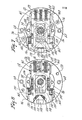
- the lockset mechanism 1 of the present invention is shown mounted in a door 2 and includes an outside hand-operated member 4 and an inside hand-operated member 6 which in the preferred embodiment are an outside lever 8 and an inside lever 10.
- the outside and inside levers 8 and 10 are used to retract a latch bolt 12 of the latch bolt assembly 14 of the lockset mechanism from a striker box 16 and striker plate 18 mounted on the door jamb 20 in conventional fashion.
- the outside operating assembly 27 of the lockset may be provided with a key-operated lock cylinder 22 mounted within the outside lever 8 and the inside operating assembly 44 of the lockset may be provided with a turn button 26 mounted within the inside lever 10.
- the lock cylinder 22 and turn button 26 may be used to move the latch bolt 12 between its extended dead bolt position shown in full lines in Figure 1 and its latching position shown by the dotted lines in Figure 1.
- the outside operating assembly 27 includes the outside lever 8 which is rotatably mounted within an outside rose 28 and includes a generally square-shaped projection 30 extending into the outside rose 28 and is held in place for rotational motion with respect thereto by a retaining ring 31.
- an outside operating cassette 32 Positioned within the outside rose 28 is an outside operating cassette 32 having upper and lower ear-like projections 34 and 36 respectively extending therefrom which fit into suitable grooves 38 and 40 respectively on the outer surface of a latch bolt assembly holder 42 which is positioned within the door 2.
- a generally circular raised portion 43 is provided on the inside surface of the outside rose 28 which extends into a mating circular groove 45 in the outside surface of the outside operating cassette 32 to provide radial alignment of the two members.
- the latch bolt assembly holder 42 provides a mechanism for mounting the latch bolt assembly 14 which contains the latch bolt 12 and includes a suitable slot 47 into which the latch bolt assembly 14 may be inserted.
- an inside operating assembly 44 includes the inside lever 10 which is pivotally mounted within an inside rose 46 and includes a generally square-shaped projection 48 extending thereinto and which has a retaining ring 50 attached thereto so that the inside lever 10 is mounted for relative rotation with respect to the inside rose 46 in a like manner as the outside operating assembly 27.
- An inside operating cassette 52 is mounted within the inside rose 46 and includes upper and lower ear-like projections 54 and 56 respectively which extend into the grooves 38 and 40 on the latch bolt assembly holder 42.
- a generally circular raised portion 57 is provided on the inside surface of the inside rose 46 which extends into a mating circular groove 59 in the outside surface of the inside operating cassette to provide radial alignment of the two members.
- a spindle 58 extends through the latch bolt assembly 14 and between the inside and outside operating cassettes 32 and 52 in a direction perpendicular to the axis of movement of the latch bolt 12.
- the lockset 1 of the present invention may be mounted as follows. It should be noted that although the lockset 1 of the present invention is shown mounted in a left-handed door 2, it is applicable to doors of any configuration.
- the outside operating cassette 32 is mounted on the latch bolt assembly holder 42 with the projections 34 and 36 received within the grooves 38 and 40 respectively of the holder 42.
- a roll pin 60 extends through the lower projection 36 into slot 62 formed in the bottom of the groove 40. This permits the outside operating cassette 32 to have limited relative movement with respect to the latch bolt assembly holder 42 while maintaining the outside operating cassette 32 and the latch bolt holder 42 together as a subassembly.
- the latch bolt assembly 14 With the outside operating cassette 32 positioned against the surface outside of the door 2 and the latch bolt assembly holder 42 positioned within the frame of the door 2, the latch bolt assembly 14 may be inserted into the latch bolt assembly holder 42 and secured thereto by means of a screw 64.
- the inside operating cassette 52 is positioned on the inside surface of the door 2 with its projections 54 and 56 extending into the grooves 38 and 40 on the latch bolt assembly holder 42.
- the outside rose 28 to which the outside lever 8 is attached includes upper and lower internally threaded posts 66 extending in a direction perpendicular to the axis of movement of the latch bolt assembly 14.
- the posts 66 extend into openings 68 in the outside operating cassette 32.
- the inside rose 46 has upper and lower openings 70 therein which align with openings 72 in the inside operating cassette 52 when the inside rose 46 is mounted thereon. Screw members 74 extend through the openings 70, 72 in the inside rose 42 and the inside operating cassette 48 into threaded engagement with the posts 66 on the outside rose 28.
- the lever portion 75 of each of the lever handles 8 and 10 extend horizontally in a direction opposite to the extension of the latch bolt 12.
- the lockset 1 will mount properly on doors regardless of variations in door thicknesses.
- the latch bolt assembly 14 is positively mounted with the latch bolt assembly holder 42 by means of the screw 64 and also the inside and outside operating cassettes 32 and 52 are held in proper alignment with the latch bolt assembly holder 28 by means of the projections 34, 36 and 54, 56 mating with the grooves 38 and 40 in the latch bolt assembly holder 42. This helps ensure proper alignment of the various components for insertion of the spindle 58.
- the inside operating cassette 52 includes a cover 76 and outside operating cassette 32 includes a cover 78 both of which are provided with two spaced tabs members 80 extending inwardly therefrom into engagement with a mating slot 82 in the metal frame of the door 2 adjacent the opening therein.
- the engagement of the tabs 80 with the slots 82 help prevent the roses 28 and 46 and the inside and outside operating cassettes 32 and 52 from rotating relative to the door.
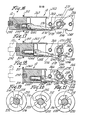
- the outside operating cassette 32 includes a housing 84 which has a central opening 86 into which the projection 30 of the outside lever 8 extends.
- the inside of the housing 84 includes a counterbore 88 concentric with the opening 86 and spaced wall portions 90 and 92 extending forwardly from the counterbore 88 in the direction of the extension of the latch bolt 14.
- the wall portions 90 and 92 taper outwardly and away from each other forming a V-shaped outer guideway 94.
- the inside surface of the housing 84 is also formed with a second set of opposed wall portions 96 and 98 spaced axially inwardly of said wall portions 90 and 92.
- the forward portions of the wall portions 96 and 98 are spaced apart a greater distance than the rearward portions forming upper and lower stop shoulders 100 (see Fig. 8).
- a rear wall portion 101 closes the end of an inner guideway 103 formed by the wall portions 96 and 98.
- An actuating member 102 is mounted in the inner guideway 94 with a boss 105 thereof mounted in the opening 86 in the housing 84 and includes a generally square-shaped opening 104 into which extends the generally square-shaped projection 30 of the outside lever 8.
- the actuating member 102 includes a base portion 106 and a reduced elongated tail portion 110 which extends from the base portion 106 and is positioned within the V-shaped outer guideway 94.
- the forward end of the tail portion 110 is provided with a raised V-shaped cam surface 112 extending inwardly past the plane of the inner surface of the tail portion 110.
- a spring plate 114 is mounted within the housing 84 of the outside operating cassette 32 in the inner guideway 103 in overlapping relationship with the actuating member 102. At its forward end the spring plate 114 includes two spaced fingers 116 and 118 each having a cam follower surface 120 thereon adapted to be engaged by the V-shaped cam surface 112 on the actuator member 102. The spring plate 114 is biased forwardly in the direction of extension of the latch bolt 14 into engagement with the cam surface 112 on the actuating member 102 by means of two lever springs 122 and 124 each of which is positioned in a suitable groove 126 provided in the housing 84 and extends from the rear wall portion 101 to the rearward end 128 of the spring plate 114.
- the spring plate 114 has a cutout portion 130 in both its upper and lower side edges which form tab-engaging surfaces 132.
- the side edges ride between the wall portions 96 and 98 (see Fig. 8) with the forward end of the spring plate 114 being wider than the rearward end.
- the shoulders 134 formed between the wider forward portion and narrow rearward portion of the spring plate 114 form stop surfaces 135 for abutting the stop shoulders 100 formed in the housing 84.
- a generally flat rack plate 136 is mounted within the housing 84 in the guideway 103 in overlapping relationship with the spring plate 114.
- the upper and lower edges of the rack plate 136 have outward extending tab portions 138 extending outward into the cutout portions 130 in the spring plate 114 in a position to be engaged by the tab-engaging surfaces 132 provided on the spring plate 114.
- the rack plate 136 also has a generally rectangular internal cutout 140, with the longer sides extending parallel to the axis of the latch bolt assembly 14.
- Gear teeth 142 are provided on the rack plate 136 adjacent one of the longer sides of the cutout 140 forming a rack which extends parallel to axis of the latch bolt assembly 14.
- the rack plate 136 is wider at its forward end between which and its narrower rearward end are formed stop shoulders 144 (see Fig. 7) adapted to abut the stop shoulders 100 formed in the housing 84.
- the forward end of the rack plate is provided with a notch 146 into which extends a lug portion 148 extending inwardly from the forward end of the actuating member 102 when the rack plate is in its forward position shown in Figure 7 to prevent rotation of the actuating member 102.
- the rack plate 136 is biased into its forward position by a spring member 149 positioned in suitable groove 151 in the housing 84 and extending between the rear wall portion 101 of the housing 84 and the rearward end of the rack plate 136.
- a pinion member 150 extends perpendicular to the axis of the latch bolt assembly 14 and is mounted within the outer operating cassette 32 and includes a set of gear teeth 152 which are in mating engagement with the gear teeth 142 on the rack plate 136.
- the pinion member 150 also includes a tubular extension portion 154 which extends through the spring plate 114, actuating member 102, and housing 84 into an opening 155 in the outside lever 8.
- the pinion member 150 includes a head portion 156 which is contained within the inside of a boss 158 which extends inwardly on the cover member 76 which provides a bearing surface for the head portion 156.
- the head portion 156 of the pinion member 150 has a generally rectangular slot 160 therein of a mating cross-section with that of the spindle 58 which extends therethrough.
- the tubular extension portion 154 includes opposed ribs 162 therein which are engagable by a drive member 164 connected to the lock cylinder 22 in the outside lever 8 to rotate the pinion member 150 between its unlocked and dead bolt positions.
- the actuating member 102 has pivotable movement about the axis of the spindle 58 and is operably attached to the outside lever 8.
- the spring plate 114 and rack plate 136 are mounted within the housing 84 for rectilinear motion in a direction parallel to the motion of the latch bolt 12 of the latch bolt assembly 14.
- the wall portions 96 and 98 of the housing 84 include wear 165 pads inserted therein which guide the spring plate 114 and rack plate 136 as shown in particularly in Figures 7 and 8.
- the wear pads 165 may be fabricated from a suitable antifriction material such as Delrin which is a polyacetal.
- the cover member 76 for the outside operating cassette 36 is provided with suitable cutout portions 166 through which the projections 34 and 36 extend to contain the operative parts of the operating housing as a unit.
- the cover member 76 is attached to the housing 84 by means of screws 168 extending through the cover member 76 into threaded bores 170 within the housing 84.
- the inside operating assembly 44 includes the inside rose 46 and the inside lever 10 attached thereto in a similar manner as the outside operating assembly by a retaining ring 50.
- the inside operating cassette 52 includes basically the same elements and is constructed similar to that of the outside operating cassette 32 which has been described above. Accordingly, the description of the various components of the inside operating cassette 52 will be relatively brief except for the differences between it and the outside operating cassette 32, which will be pointed out in more explicated detail below.
- the inside operating cassette 52 includes a housing 172 having the projections 54 and 56 extending therefrom and in which is mounted for pivotal movement an inside actuating member 174 in a guideway 176 similar to that described above in connection with the outside actuating member 102.
- the inside actuating member 174 includes a central generally square-shaped opening 178 into which the square-shaped projection 48 of the inside lever 10 projects as well as a raised V-shaped cam portion 180.
- a spring plate 182 having cam surfaces 183 for engagement with the cam surface 180 on the actuating member 174 is mounted in a guideway 184 in the housing 172.
- the spring plate 182 is spring-biased forwardly by spring members 186.
- the spring plate 182 also includes a cutout portion 188 in each of its side edges forming tab-engaging surfaces 190 and stop shoulders 192 adapted to engage stop shoulders 194 (see Fig. 11) in the housing 172.
- a rack plate 196 having gear teeth 198 provided adjacent a rectangular cutout 200 forming a rack 202 is mounted in the guideway 184 overlapping the spring plate 182.
- the rack plate 196 is spring-biased forwardly by a spring member 204.
- the rack plate 196 also includes stop shoulders 205 adapted to engage the stop shoulder 194 in the housing 172 and outwardly extending tabs 206 extending into the cutout portions 188 in a position to be engaged by the tab-engaging portions 190 of the spring plate 182.
- the guideway 184 also includes wear inserts 207 of the same type as described in connection above in connection with the outside housing 84.
- the forward end of the rack plate 196 of the inside operating assembly 44 is foreshortened and does not include a notch so that when it is in its forward dead bolt position as shown in Figure 11 and the tabs 206 are in engagement with the tab-engaging surfaces 190 of the spring plate, the forward end does not come into engagement with the lug portion 209 on the actuating member 174.
- the actuating member 174 is free to pivot when the rack plate 196 is in its forward dead bolt position.
- a pinion member 210 includes gear teeth 212 thereon in mating engagement with the teeth 198 on the rack plate 196.
- the pinion member 210 includes a tubular extension 213 having opposed ribs 214, 216 therein which extend through the inside operating cassette 52 into an opening 218 in the inside lever 10.
- the pinion member 210 further includes a head portion 220 which is contained within the boss 221 of the inside cover 78.
- the cover 78 is attached to the housing 172 by means of screws 222 which are threadedly engaged with the housing 172.
- the head portion 220 of the pinion member 210 also includes a slot 224 through which one end of the spindle 58 extends.
- the turn button 26 includes a knob 226 having a rod 228 extending inwardly therefrom.
- the end of the rod 228 includes two opposed radial extending ear portions 230 and 232 for engaging the opposed ribs 214 and 216 in the tubular extension 212 of the inside pinion member 210.
- a cam member 234 is mounted on the rod 228 having a cam slot 236 therein.
- a cam follower 238 in the form of a roll pin extends radially out from the rod into the cam slot 236.
- a spring 240 is provided between the cam member 234 and the knob 226 to bias the knob 226 outwardly.
- the cam member 234 includes a bump 242 on its circumference which mates with an indention 244 in the opening 218 in the inside lever 10 to prevent rotation of the cam member 234 with respect to the lever 10.
- the cam member 234 also includes inwardly projecting tongues 246 having shoulders 248 thereon.
- the turn button 26 is mounted in the opening 218 of the inside lever 10 with the body 250 of the cam member 234 engaging an outwardly facing shoulder 252 in the lever 8 and the shoulder 248 on the tongues 246 engaging an inwardly facing shoulder 254 in the lever 10.
- the rod 228 When mounted in the lever 10, the rod 228 extends into the pinion member 210 of the inside operating assembly.
- the cam slot 236 extends partially around the circumference of the body 250 of the cam member and includes a generally straight portion 256 and an outwardly extending detent portion 258 which acts as a detent for the cam follower 238.
- the latch bolt 12 of the latch bolt assembly 14 in shown movable between an extended position in Figure 16, a latching position in Figure 17 and an open position in Figure 18.
- the latch bolt assembly 14 includes a latch case 260 having two spaced latch plates 262 and 264 ( Figure 2) extending rearwardly therefrom.
- the latch plates 262 and 264 are held mounted together by means of bushings 266.
- the latch bolt assembly 14 is mounted within the slot 43 in the latch bolt assembly holder 42 with the screw 64 which attaches the latch bolt assembly 14 to the latch bolt assembly holder 42 extending through the rearward one of the bushings 266.
- a hub member 268 upon which two lever plates 270 are mounted for rotation therewith is mounted between the two latch plates 262 and 264 in suitable openings 272 therein.
- the hub member 268 has a generally rectangular bore 274 therethrough of a shape to receive the spindle 58.
- the bolt 12 is mounted within the latch case 260 and has an arm 276 extending rearwardly therefrom toward the lever plates 270.
- the arm 276 is pivotably attached at its forward end to the bolt 12 and at its rearward end has a pivot pin 278 extending through an elongated slot 280 in the lever plate 270.
- a guide 282 having opposed side walls in which the arm 276 is positioned is also pivotally attached to the rearward end of the bolt.
- a spring-biased dowel 284 is mounted in the bolt head and has its end face engaging one corner on the forward portion of the arm 276. This serves to bias the arm 276 in a direction such that the pivot pin 278 will engage the edge 286 of the latch plates 262 and 264 in a cutout portion 288. At the forward end of the cutout portion 288 there is a deeper cutout portion 290 forming a detent into which the pivot pin 278 is moved when the latch bolt 12 is moved into its extended dead bolt position.
- the latch bolt 12 includes a bevelled forward portion 292 in a manner known in the art.
- the latch bolt 12 also includes a wear strip 294 of suitable wear resistance material (see Figure 25) of the type mentioned in connection with the wear pads 165 which extends about the exposed portions of the latch bolt 12 thereof including the bevelled forward portion 292 as well as the front and rear sides 296 and 298.
- the wear strip 294 is mounted in a groove 300 in the latch bolt 12 and includes at the end of its front side a raised portion 302 which extends into the body of the latch bolt 12 and which is staked thereover.
- the spindle 58 extends between the two pinions 150 and 210 and through the hub member 268 of the latch bolt assembly 14.
- the components of the inside operating cassette 52 are in substantially the same position as the outside components with the spring plate 182 biased forwardly in the housing 172 by the springs 186 against the cam surface 180 on the actuating member 174.
- the rack plate 196 is spring-biased outwardly until its tabs 206 abut the tab-engaging portions 190 on the spring plate 182. In the case of the inside operating cassette however, the rack plate 196 does not engage the lug portion 208 on the actuating member 174 and there is no blocking engagement thereof. Thus, the inside lever 10 is free to turn enabling the latch bolt 12 to be retracted.
- the actuating member 174 pivots about the axis of the spindle 58 and the cam surfaces 180 thereof engage the cam surfaces 183 on the end of the spring plate 182 causing the spring plate 182 to move rearwardly in a linear direction. Due to the engagement of the tab-engaging surfaces 190 on the spring plate 182 with the tabs 206 on the rack plate 196, the rack plate 196 will also be moved rearwardly in a linear direction. The rearward movement of the rack plate 196 causes the pinion member 210 to rotate thereby rotating the spindle 58 and the hub member 268 of the latch bolt assembly 14 causing complete retraction of the latch bolt 12.
- the components of the outer operating cassette 32 are positioned as shown in Figure 9.
- the spring plate 114 is forced by its associated springs 186 into its forward position wherein the cam surfaces 120 abut the cam surface 112 on the actuating member 102 and maintains the actuating member 102 in its central position in the guideway 94 and the outside lever 8 horizontal.
- the spring plate 182 and actuator member 174 in the inside cassette 52 are similarly positioned (see Fig. 13).
- the rack plates 114 and 182 are held in the latching position by means of the inside pinion member 210 being held from rotation into its dead bolt position by means of the ribs 214, 216 in the extension 213 thereof engaging the ear portions 230, 232 on the rod of the turn button as shown in Figure 20 when the turn button 26 is in its unlocked position with the cam follower 258 positioned in the detent portion 258 of the cam slot 236. It is to be noted that the movement of the rack plates 114 and 182 from their open to their intermediate positions under the influence of their springs 149 and 204 serves to move the latch bolt from its retracted position to its latching position. This eliminates the need for a spring in the latch bolt assembly 14.
- the pinion member 210 Due to the lost motion connection between the turn button 26 and pinion member 210, the pinion member 210 is able to rotate from its latching position to its open position relative to the ⁇ turn button thereby permitting the latch bolt 12 to be retracted when the door closes.
- the turn button 26 and lock member 22 are connected to their respective pinion members 210 and 150 to drive them from their intermediate latching position into the dead bolt position merely by turning the turn button or rotating the lock with the key. This causes the pinions 210 and 150 to rotate the spindle 58 which in turn turns the hub member 268 of the latch bolt assembly 14 which drives the latch bolt 12 forward. If the key member is turned, the connection of the ear portions 230 and 232 of the turn button 26 with the ribs 214, 216 of the extension portion 213 of the inside pinion 210 causes the turn button 26 to move into its locked position (Fig. 19) wherein the cam follower 238 is moved out of the detent portion 258 in the cam surface 236 onto the straight portion 256 thereof.
- the lockset of the present invention includes a latch front 304 which is adaptable for both a bevelled door and a straight front door.
- the latch front 304 has enlarged recesses 306 on its inside surface 308 to accommodate the tabs 310 of the casing of the lock assembly 14.
- the latch front 304 is held in the door by means of screw members 312 and includes an opening 314 therein through which the latch bolt 12 extends.
- the opening 314 of the front 304 is bevelled outwardly on both sides 3° with a flat in the middle.
Applications Claiming Priority (2)
| Application Number | Priority Date | Filing Date | Title |
|---|---|---|---|
| US537896 | 1983-09-30 | ||
| US06/537,896 US4594864A (en) | 1983-09-30 | 1983-09-30 | Lockset assembly |
Publications (3)
| Publication Number | Publication Date |
|---|---|
| EP0136885A2 true EP0136885A2 (de) | 1985-04-10 |
| EP0136885A3 EP0136885A3 (en) | 1986-05-14 |
| EP0136885B1 EP0136885B1 (de) | 1989-10-25 |
Family
ID=24144552
Family Applications (1)
| Application Number | Title | Priority Date | Filing Date |
|---|---|---|---|
| EP84306606A Expired EP0136885B1 (de) | 1983-09-30 | 1984-09-28 | Schloss |
Country Status (14)
| Country | Link |
|---|---|
| US (1) | US4594864A (de) |
| EP (1) | EP0136885B1 (de) |
| JP (1) | JPS60501613A (de) |
| KR (1) | KR890003023B1 (de) |
| AU (1) | AU564880B2 (de) |
| BR (1) | BR8407107A (de) |
| CA (1) | CA1237157A (de) |
| DE (1) | DE3480291D1 (de) |
| ES (1) | ES536353A0 (de) |
| HK (1) | HK26790A (de) |
| IL (1) | IL72942A (de) |
| PH (1) | PH21411A (de) |
| SG (1) | SG6190G (de) |
| WO (1) | WO1985001542A1 (de) |
Families Citing this family (42)
| Publication number | Priority date | Publication date | Assignee | Title |
|---|---|---|---|---|
| EP0136891B1 (de) * | 1983-09-30 | 1990-11-14 | Emhart Industries, Inc. | Schloss |
| US4741190A (en) * | 1986-10-03 | 1988-05-03 | Emhart Industries, Inc. | Lockset assembly |
| US4763934A (en) * | 1986-12-04 | 1988-08-16 | Caterpillar Inc. | Door latch and lock assembly |
| US4843851A (en) * | 1987-09-23 | 1989-07-04 | Emhart Industries Inc. | Locking mechanism for multifunctional electronic lock |
| WO1989008763A1 (en) * | 1988-03-15 | 1989-09-21 | John Russell Watts | A door lock |
| AU614604B2 (en) * | 1988-03-15 | 1991-09-05 | Jorgenson-Watts Pty Ltd | A door lock |
| CA1337379C (en) * | 1988-07-11 | 1995-10-24 | John Mckernan | Sleeve for dead bolt |
| IL90915A (en) * | 1988-07-29 | 1991-05-12 | Emhart Ind | Lockset having improved actuator |
| US4887442A (en) * | 1988-09-27 | 1989-12-19 | Emhart Industries, Inc. | Electronic lockset assembly and control |
| US5368345A (en) * | 1990-10-12 | 1994-11-29 | Watts; John R. | Door lock |
| US5177987A (en) * | 1991-07-12 | 1993-01-12 | Shen Chao C | Key-in-lever type door lock used for handicapped people |
| DE69325777T2 (de) * | 1992-06-09 | 2000-03-09 | Hoppe Ag | Riegel und türschloss |
| AU662657B2 (en) * | 1992-10-09 | 1995-09-07 | Gainsborough Hardware Industries Limited | Dual function lock mechanism |
| SG52685A1 (en) * | 1992-10-09 | 1998-09-28 | Gainsborough Hardward Ind Limi | Privacy snib mechanism |
| US5651568A (en) * | 1992-10-09 | 1997-07-29 | Gainsborough Hardware Industries, Limited | Privacy snib mechanism |
| US5516160A (en) * | 1994-04-11 | 1996-05-14 | Master Lock Company | Automatic deadbolts |
| US5657653A (en) * | 1995-08-10 | 1997-08-19 | Schlage Lock Company | Dual lock with simultaneous retraction of latch and deadbolt by inside lever and uncoulpler between driving spindle and the lever |
| US6090106A (en) | 1996-01-09 | 2000-07-18 | Gyrus Medical Limited | Electrosurgical instrument |
| FR2770869B1 (fr) * | 1997-11-07 | 2001-09-07 | Stremler | Dispositif formant pene demi-tour |
| US5983687A (en) * | 1997-12-29 | 1999-11-16 | Shen; Mu-Lin | Positioning device for a cylindrical lock |
| US6101856A (en) * | 1998-12-14 | 2000-08-15 | Sargent Manufacturing Company | Free-wheeling lever handle lock mechanism |
| US5987947A (en) * | 1999-01-19 | 1999-11-23 | Shen; Mu-Lin | Manual control device for a pickproof lock assembly |
| CA2261511C (en) * | 1999-02-12 | 2003-06-03 | Chia Pel Liang | Door lock device |
| GB2359849B (en) * | 2000-03-04 | 2002-10-23 | Basta Hardware Ltd | Spring cassettes |
| GB0005752D0 (en) * | 2000-03-11 | 2000-05-03 | Banham Patent Locks Ltd | Lock |
| US6698803B2 (en) | 2001-01-12 | 2004-03-02 | Schlage Lock Company | Door latching mechanism |
| US6568725B2 (en) * | 2001-02-07 | 2003-05-27 | Schlage Lock Company | Lock chassis |
| US6860529B2 (en) | 2001-11-02 | 2005-03-01 | Newfrey Llc | Push button with latch kick-off |
| AU2004200529B2 (en) * | 2002-12-20 | 2006-01-05 | Assa Abloy Australia Pty Limited | A Three Mode Lock |
| US6988751B2 (en) * | 2003-03-05 | 2006-01-24 | Schlage Lock Company | Non-rotational lock chassis assembly |
| SG158759A1 (en) * | 2004-01-30 | 2010-02-26 | Assa Abloy Australia Pty Ltd | A three mode lock |
| GB2425806B (en) * | 2004-01-30 | 2007-12-05 | Assa Abloy Australia Pty Ltd | A three mode lock |
| US7698917B2 (en) | 2006-03-06 | 2010-04-20 | Handytrac Systems, Llc | Electronic deadbolt lock with a leverage handle |
| CN101245676A (zh) * | 2007-02-16 | 2008-08-20 | 阿萨阿布洛伊澳大利亚有限公司 | 带有烟雾警报器接口的锁 |
| NZ594709A (en) * | 2010-09-09 | 2012-03-30 | Assa Abloy Australia Pty Ltd | Low profile combination lock and latch for sliding cavity door of varying widths |
| EP2997209B1 (de) * | 2013-05-15 | 2021-02-17 | TriTeq Lock and Security LLC | Schloss |
| CN104453364B (zh) * | 2014-12-19 | 2017-01-18 | 青岛橡胶谷知识产权有限公司 | 一种安全润滑门把手 |
| US10858863B2 (en) * | 2015-04-24 | 2020-12-08 | Invue Security Products Inc. | Self-locking lock for merchandise security |
| WO2017035597A1 (en) * | 2015-09-02 | 2017-03-09 | Tnbt Holdings Pty Ltd | A latchbolt retractor, a latchbolt assembly, and an assembly for a lockset |
| WO2017165654A1 (en) * | 2016-03-25 | 2017-09-28 | Schlage Lock Company Llc | Interchangeable handle lockset |
| US11091934B2 (en) | 2018-01-11 | 2021-08-17 | Schlage Lock Company Llc | Apparatus and method for installing door locks |
| IT201800005282A1 (it) * | 2018-05-11 | 2019-11-11 | Scrocco ammortizzato e relativo inserto smorzatore |
Citations (5)
| Publication number | Priority date | Publication date | Assignee | Title |
|---|---|---|---|---|
| FR1136957A (fr) * | 1955-03-09 | 1957-05-22 | Sargent & Co | Perfectionnement apporté aux dispositifs de fermeture à pêne pour portes ou analogues |
| US2814194A (en) * | 1952-08-09 | 1957-11-26 | Nat Lock Co | Key lock construction for doors or closures |
| US2885880A (en) * | 1956-05-15 | 1959-05-12 | Independent Lock Co | Turnbutton assembly for cylindrical locks |
| US3390910A (en) * | 1966-09-01 | 1968-07-02 | Emhart Corp | Latch control device |
| US4333324A (en) * | 1979-05-02 | 1982-06-08 | Norris Industries, Inc. | Spring/dead bolt lock assembly |
Family Cites Families (7)
| Publication number | Priority date | Publication date | Assignee | Title |
|---|---|---|---|---|
| US2694918A (en) * | 1952-08-14 | 1954-11-23 | American Hardware Corp | Door latch operating mechanism |
| US3036850A (en) * | 1959-04-13 | 1962-05-29 | Yale & Towne Mfg Co | Tubular lock |
| US2996326A (en) * | 1959-04-20 | 1961-08-15 | Schlage Lock Co | Faceplate for beveled and rabbeted doors |
| US3241874A (en) * | 1963-10-28 | 1966-03-22 | Russell | Plate with tab for retaining a unit lock in position on a door |
| US3279836A (en) * | 1964-02-24 | 1966-10-18 | Emhart Corp | Dead latch construction |
| US4031725A (en) * | 1975-08-11 | 1977-06-28 | Reid Floyd F | Door lock |
| US4193619A (en) * | 1978-05-15 | 1980-03-18 | Acme General Corporation | Door latch |
-
1983
- 1983-09-30 US US06/537,896 patent/US4594864A/en not_active Expired - Lifetime
-
1984
- 1984-09-04 JP JP59503383A patent/JPS60501613A/ja active Pending
- 1984-09-04 AU AU33939/84A patent/AU564880B2/en not_active Ceased
- 1984-09-04 BR BR8407107A patent/BR8407107A/pt not_active IP Right Cessation
- 1984-09-04 WO PCT/US1984/001401 patent/WO1985001542A1/en unknown
- 1984-09-14 IL IL72942A patent/IL72942A/xx unknown
- 1984-09-27 PH PH31274A patent/PH21411A/en unknown
- 1984-09-28 EP EP84306606A patent/EP0136885B1/de not_active Expired
- 1984-09-28 CA CA000464312A patent/CA1237157A/en not_active Expired
- 1984-09-28 ES ES536353A patent/ES536353A0/es active Granted
- 1984-09-28 DE DE8484306606T patent/DE3480291D1/de not_active Expired
-
1985
- 1985-05-25 KR KR1019850700060A patent/KR890003023B1/ko not_active IP Right Cessation
-
1990
- 1990-01-26 SG SG61/90A patent/SG6190G/en unknown
- 1990-04-04 HK HK267/90A patent/HK26790A/xx unknown
Patent Citations (5)
| Publication number | Priority date | Publication date | Assignee | Title |
|---|---|---|---|---|
| US2814194A (en) * | 1952-08-09 | 1957-11-26 | Nat Lock Co | Key lock construction for doors or closures |
| FR1136957A (fr) * | 1955-03-09 | 1957-05-22 | Sargent & Co | Perfectionnement apporté aux dispositifs de fermeture à pêne pour portes ou analogues |
| US2885880A (en) * | 1956-05-15 | 1959-05-12 | Independent Lock Co | Turnbutton assembly for cylindrical locks |
| US3390910A (en) * | 1966-09-01 | 1968-07-02 | Emhart Corp | Latch control device |
| US4333324A (en) * | 1979-05-02 | 1982-06-08 | Norris Industries, Inc. | Spring/dead bolt lock assembly |
Also Published As
| Publication number | Publication date |
|---|---|
| AU3393984A (en) | 1985-04-23 |
| ES8603011A1 (es) | 1985-12-01 |
| ES536353A0 (es) | 1985-12-01 |
| CA1237157A (en) | 1988-05-24 |
| SG6190G (en) | 1990-07-13 |
| US4594864A (en) | 1986-06-17 |
| HK26790A (en) | 1990-04-12 |
| IL72942A0 (en) | 1984-12-31 |
| PH21411A (en) | 1987-10-15 |
| KR890003023B1 (ko) | 1989-08-18 |
| DE3480291D1 (en) | 1989-11-30 |
| JPS60501613A (ja) | 1985-09-26 |
| EP0136885A3 (en) | 1986-05-14 |
| KR850700054A (ko) | 1985-10-21 |
| EP0136885B1 (de) | 1989-10-25 |
| AU564880B2 (en) | 1987-08-27 |
| IL72942A (en) | 1987-12-31 |
| WO1985001542A1 (en) | 1985-04-11 |
| BR8407107A (pt) | 1985-08-27 |
Similar Documents
| Publication | Publication Date | Title |
|---|---|---|
| EP0136885B1 (de) | Schloss | |
| US4276760A (en) | Two-bolt lockset with simultaneous locking and unlocking of its bolts | |
| US5713612A (en) | Adjustable interconnected lock assembly with automatic deadbolt | |
| EP0136891B1 (de) | Schloss | |
| US3750433A (en) | Mortise lock retract mechanism | |
| US4118056A (en) | Mortise lock | |
| US4418552A (en) | Simultaneously locking and unlocking dead bolt and lock latch with panic unlocking | |
| US6578888B1 (en) | Mortise lock with automatic deadbolt | |
| US4255953A (en) | Combination spring/dead bolt lock | |
| EP1064444B1 (de) | Elektromagnetische verriegelungsvorrichtung | |
| WO1991019068A1 (en) | Electro-mechanical lock with rotary bolt | |
| US5765410A (en) | Locks | |
| US3159994A (en) | Door latch and lock | |
| US5020343A (en) | Lockset having improved actuator | |
| CA1330571C (en) | Panic proof passage lock set | |
| US4578967A (en) | Combined door latch and deadbolt arrangement | |
| GB2185059A (en) | Multiple latch mechanism | |
| US4617811A (en) | Mechanism for operating a drop-bolt door lock | |
| US3819214A (en) | Cylindrical lock set | |
| US4741190A (en) | Lockset assembly | |
| US4294089A (en) | Latchbolt rim lock | |
| US3141320A (en) | Latchbolt holdback for doorlocks | |
| AU567256B2 (en) | Lockset assembly | |
| US4784416A (en) | Door latch | |
| CA1135070A (en) | Combination spring/dead bolt lock |
Legal Events
| Date | Code | Title | Description |
|---|---|---|---|
| PUAI | Public reference made under article 153(3) epc to a published international application that has entered the european phase |
Free format text: ORIGINAL CODE: 0009012 |
|
| AK | Designated contracting states |
Designated state(s): BE DE FR GB IT NL |
|
| PUAL | Search report despatched |
Free format text: ORIGINAL CODE: 0009013 |
|
| AK | Designated contracting states |
Kind code of ref document: A3 Designated state(s): BE DE FR GB IT NL |
|
| 17P | Request for examination filed |
Effective date: 19860808 |
|
| 17Q | First examination report despatched |
Effective date: 19880323 |
|
| GRAA | (expected) grant |
Free format text: ORIGINAL CODE: 0009210 |
|
| AK | Designated contracting states |
Kind code of ref document: B1 Designated state(s): BE DE FR GB IT NL |
|
| REF | Corresponds to: |
Ref document number: 3480291 Country of ref document: DE Date of ref document: 19891130 |
|
| ET | Fr: translation filed | ||
| ITF | It: translation for a ep patent filed |
Owner name: UFFICIO BREVETTI RICCARDI & C. |
|
| RAP2 | Party data changed (patent owner data changed or rights of a patent transferred) |
Owner name: EMHART INDUSTRIES, INC. |
|
| NLT2 | Nl: modifications (of names), taken from the european patent patent bulletin |
Owner name: EMHART INDUSTRIES, INC. TE TOWSON, MARYLAND, VER. |
|
| PGFP | Annual fee paid to national office [announced via postgrant information from national office to epo] |
Ref country code: FR Payment date: 19900816 Year of fee payment: 7 |
|
| PLBE | No opposition filed within time limit |
Free format text: ORIGINAL CODE: 0009261 |
|
| STAA | Information on the status of an ep patent application or granted ep patent |
Free format text: STATUS: NO OPPOSITION FILED WITHIN TIME LIMIT |
|
| PGFP | Annual fee paid to national office [announced via postgrant information from national office to epo] |
Ref country code: DE Payment date: 19900817 Year of fee payment: 7 |
|
| PGFP | Annual fee paid to national office [announced via postgrant information from national office to epo] |
Ref country code: BE Payment date: 19900829 Year of fee payment: 7 |
|
| ITTA | It: last paid annual fee | ||
| PGFP | Annual fee paid to national office [announced via postgrant information from national office to epo] |
Ref country code: NL Payment date: 19900930 Year of fee payment: 7 |
|
| 26N | No opposition filed | ||
| PGFP | Annual fee paid to national office [announced via postgrant information from national office to epo] |
Ref country code: GB Payment date: 19910716 Year of fee payment: 8 |
|
| PG25 | Lapsed in a contracting state [announced via postgrant information from national office to epo] |
Ref country code: BE Effective date: 19910930 |
|
| BERE | Be: lapsed |
Owner name: EMHART INDUSTRIES INC. Effective date: 19910930 |
|
| PG25 | Lapsed in a contracting state [announced via postgrant information from national office to epo] |
Ref country code: NL Effective date: 19920401 |
|
| NLV4 | Nl: lapsed or anulled due to non-payment of the annual fee | ||
| PG25 | Lapsed in a contracting state [announced via postgrant information from national office to epo] |
Ref country code: FR Effective date: 19920529 |
|
| PG25 | Lapsed in a contracting state [announced via postgrant information from national office to epo] |
Ref country code: DE Effective date: 19920602 |
|
| REG | Reference to a national code |
Ref country code: FR Ref legal event code: ST |
|
| PG25 | Lapsed in a contracting state [announced via postgrant information from national office to epo] |
Ref country code: GB Effective date: 19920928 |
|
| GBPC | Gb: european patent ceased through non-payment of renewal fee |
Effective date: 19920928 |