EP0136740B1 - Process for manufacturing parcels of annular, magnetic or other plates and installation for carrying it out - Google Patents
Process for manufacturing parcels of annular, magnetic or other plates and installation for carrying it out Download PDFInfo
- Publication number
- EP0136740B1 EP0136740B1 EP84201144A EP84201144A EP0136740B1 EP 0136740 B1 EP0136740 B1 EP 0136740B1 EP 84201144 A EP84201144 A EP 84201144A EP 84201144 A EP84201144 A EP 84201144A EP 0136740 B1 EP0136740 B1 EP 0136740B1
- Authority
- EP
- European Patent Office
- Prior art keywords
- segments
- sheet metal
- pile
- station
- layers
- Prior art date
- Legal status (The legal status is an assumption and is not a legal conclusion. Google has not performed a legal analysis and makes no representation as to the accuracy of the status listed.)
- Expired
Links
Images


Classifications
-
- H—ELECTRICITY
- H02—GENERATION; CONVERSION OR DISTRIBUTION OF ELECTRIC POWER
- H02K—DYNAMO-ELECTRIC MACHINES
- H02K15/00—Methods or apparatus specially adapted for manufacturing, assembling, maintaining or repairing of dynamo-electric machines
- H02K15/02—Methods or apparatus specially adapted for manufacturing, assembling, maintaining or repairing of dynamo-electric machines of stator or rotor bodies
- H02K15/024—Methods or apparatus specially adapted for manufacturing, assembling, maintaining or repairing of dynamo-electric machines of stator or rotor bodies with slots
-
- Y—GENERAL TAGGING OF NEW TECHNOLOGICAL DEVELOPMENTS; GENERAL TAGGING OF CROSS-SECTIONAL TECHNOLOGIES SPANNING OVER SEVERAL SECTIONS OF THE IPC; TECHNICAL SUBJECTS COVERED BY FORMER USPC CROSS-REFERENCE ART COLLECTIONS [XRACs] AND DIGESTS
- Y10—TECHNICAL SUBJECTS COVERED BY FORMER USPC
- Y10T—TECHNICAL SUBJECTS COVERED BY FORMER US CLASSIFICATION
- Y10T29/00—Metal working
- Y10T29/49—Method of mechanical manufacture
- Y10T29/49002—Electrical device making
- Y10T29/49009—Dynamoelectric machine
-
- Y—GENERAL TAGGING OF NEW TECHNOLOGICAL DEVELOPMENTS; GENERAL TAGGING OF CROSS-SECTIONAL TECHNOLOGIES SPANNING OVER SEVERAL SECTIONS OF THE IPC; TECHNICAL SUBJECTS COVERED BY FORMER USPC CROSS-REFERENCE ART COLLECTIONS [XRACs] AND DIGESTS
- Y10—TECHNICAL SUBJECTS COVERED BY FORMER USPC
- Y10T—TECHNICAL SUBJECTS COVERED BY FORMER US CLASSIFICATION
- Y10T29/00—Metal working
- Y10T29/53—Means to assemble or disassemble
- Y10T29/5313—Means to assemble electrical device
- Y10T29/53143—Motor or generator
- Y10T29/53161—Motor or generator including deforming means
-
- Y—GENERAL TAGGING OF NEW TECHNOLOGICAL DEVELOPMENTS; GENERAL TAGGING OF CROSS-SECTIONAL TECHNOLOGIES SPANNING OVER SEVERAL SECTIONS OF THE IPC; TECHNICAL SUBJECTS COVERED BY FORMER USPC CROSS-REFERENCE ART COLLECTIONS [XRACs] AND DIGESTS
- Y10—TECHNICAL SUBJECTS COVERED BY FORMER USPC
- Y10T—TECHNICAL SUBJECTS COVERED BY FORMER US CLASSIFICATION
- Y10T29/00—Metal working
- Y10T29/53—Means to assemble or disassemble
- Y10T29/5313—Means to assemble electrical device
- Y10T29/5317—Laminated device
Definitions
- the present invention relates to a method of manufacturing packages of magnetic or other sheets of annular shape for small and medium electric machines, in particular alternators for motor vehicles, from stamped sheets, having slots open inwards having a narrowing at their entry and which are formed by arms directed radially inward and thickening at their end.
- the invention also relates to an installation for implementing the method.
- the document FR-A-2 487 597 describes a packaging device for dynamo sheets subdivided into segments, one or more automatic feeding stations I, II, III, for the crown segments are associated with a rotary table, whose plate 24 is made with stacking stops 18.
- An electric servo-motor 15 is provided for the step-by-step movement of the rotary table.
- a computer numerical control device freely programmable with display screen terminal, is provided, into which the number of crown segments for 360 ° and the size of the overlap are introduced.
- the present invention aims to overcome these drawbacks by proposing a method of manufacturing packages and assembling magnetic or other sheets of annular shape making it possible on the one hand to reduce the quantity of waste and on the other hand to eliminate internal tensions of the stamped rings thus making it possible to respect the required tolerances without any subsequent machining of the stator.
- the essential advantage of the invention is linked to the fact that a ring is formed by juxtaposed segments, their number can vary from two to six but preferably three are used. In this way, one eliminates on the one hand the internal tensions created on a closed ring during the stamping thus allowing the respect of the required tolerances without a machining of the stator is necessary, and on the other hand the quantity of sheet metal waste.
- the assembly of the rings and packages is done automatically according to phases b to f of claim 1.
- the centering of the package of the segments from the inside and the outside before its final assembly makes it possible to obtain the required tolerances.
- the angular offset between two consecutive layers is necessary to ensure the assembly of the package of sheets and to prevent the package from separating into as many cylinder segments as there are segments forming a ring, and, on the other hand, to allow cancellation any differences in sheet thickness.
- the staggered arrangement of the layers of segments by an angle a / 2 is obtained by the alternating advancement of two groups of n conveyor plates regularly distributed around the adjustment plate, each being supplied by 2n corresponding stores.
- the possible differences in sheet thickness affecting the parallelism of the package are compensated for by rotating the stacking disc at an angle at least n times, each rotation occurring after a predetermined number of layers of segments. are piled up.
- a sheet bundle with a height H ′ representing approximately 80 to 95% of the prescribed height H is first formed, the height H 'and, depending on the difference remaining between the measured height H' and the prescribed height H, we complete either with at least one layer of sheet metal segments of thickness D ', smaller than D up to the height about (HD) if H 'has not reached approximately (HD), then complete with a layer of sheet metal segments D, or complete with one or more layers of sheet metal segments of thickness Up to at height H.
- the last layer of the package be formed by segments of thickness D.
- the partial package is formed from a number of segments of sheet metal of thickness D such that the difference between the height H and the sum of all the maximum positive tolerances of the thickness of the sheet metal segments is, in the most unfavorable case, still at most equal to D.
- the invention also relates to an installation for implementing the method.
- the installation according to the invention is characterized in that it comprises at least one stacking station and one assembly station by riveting, in that the stacking station comprises: at least n stores filled with segments of sheet metal, regularly distributed around an adjustment plate whose diameter corresponds to the inside diameter of the ring to be completed, n conveyor plates to bring n stores n sheet metal segments against the adjustment plate which is provided with n retaining members of said segments, a stacking disc disposed below said adjustment plate provided with guide rods, at least two per sheet segment engaging in corresponding slots of segments when they fall after removal of the conveyor plates, means for ensuring the angular offset between two layers of consecutive sheet metal segments.
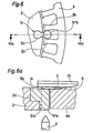
- Figures 6, 6a and 7, 7a are views similar to Figures 5 and 5a showing the support of a segment by a holding member.
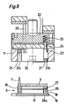
- Figure 8 is a side view in section of some elements of the crimping station.
- the complete installation for implementing the process illustrated in FIG. 1 comprises six main work stations, the most of which important are the stacking station 1 and the crimping station VI.
- the work stations of the installation in the order of the manufacturing process are as follows: The stacking station I, the station II for measuring the height of a partial package, the sheet metal stacking stations III with thickness D 'less than thickness D and IV for stacking sheets of thickness D in order to complete the partial package with layers of thickness D'and / or D depending on the measurement result at station II , the station V for centering segments and setting up rivets and finally the station VI for crimping.
- the stacking station 1 shown quite diagrammatically comprises six magazines 1a and 1b regularly distributed around an adjustment plate 2.
- the annular segments 3 have an angular dimension of 120 ° and a thickness D.
- the segments 3 represented in phantom lines have been supplied by the stores 1a and brought by the transport trays 4a which are represented quite schematically.
- the magazines 1b, offset by 60 ° relative to the magazines 1a will supply segments 3 brought by the plates 4b to form one or more layers of segments offset by 60 ° relative to the segments supplied by the magazines 1a, in order to allow, d on the one hand, to assemble a package and on the other hand, to compensate for any errors in the nominal value of the thickness of the sheet metal segments.
- the segments of the first layer are brought in, for example, by the plates 4a, and of the following by the plates 4b.
- the segments 3 are held by the retaining members 5 facing the corresponding magazines and transport trays.
- the elements of the stacking station 1 will be described in more detail with the aid of Figures 2 to 7a.
- a conveyor device brings a packet of segments of a height H ' ⁇ H, H being the required height, to the measurement station II where the height H' is measured exactly and then the packet passes to stations III and IV comprising, the first, three stores and three transport platforms, and the second, six.
- the magazines of station III are filled with segments of thickness D less than D, while those of station IV are filled with segments of thickness D.
- the packet is completed by layers of segments from station III and / or IV.
- layers of segments from station III and / or IV For example, if we have to form a packet of height 21 mm by sheet metal segments of thickness 1 mm, we form at the stacking station 1 a packet of nineteen layers, we bring the packet at the measurement station Il to measure its height H 'and then the package goes to stations III and IV where it is completed so that its height is the closest to 21 mm and above all within the required tolerances.
- Figure 2 there is shown a partial side view of the stacking station. There is in particular shown the adjustment plate 2 supporting the holding elements 5, and below, the stacking disc 6 provided with six guide rods 7 regularly distributed on the disc 6. Each of the rings 3 is guided during its fall by two of the rods 7 which engage in two slots spaced 60 °.
- Figure 4 is a top view of Figure 2. There is shown in broken lines in Figure 2 several layers of segments and in Figure 4 we see the upper layer.
- FIG. 3 we see in solid lines three segments 3 of a ring brought by conveyor plates 4a, only one of which is shown in the lower part of the figure, towards the adjustment plate 2.
- the only carrier plate 4a shown in Figure 3 is mounted on a slide and is driven by a double-acting cylinder.
- Its end 8 located towards the adjustment plate 2 has the shape of a ring segment of dimensions corresponding to those of an annular segment of sheet metal 3, formed in a recess 9 of the plate 4a.
- the recess 9 (fig.
- the annular end 6 of a plate 4a or 4b is provided in its middle with a notch 10 of dimensions and shape corresponding to those of the body 5a (which will be described later) of a holding member 5, projecting radially by relative to the adjustment plate 2, in order to allow the transporting plate 4a or 4b to bring the transported segment 3 against the adjustment plate 2.
- the notch 10 is located below a slot 3a limited by two arms consecutive 3b of a ring segment 3.
- the outer periphery of a segment is provided with notches 3c used for centering and guiding segments 3 in the stores and on the transport trays.
- FIG. 5 represents a partial view of an annular segment 3 supported by a transporter plate 4a or 4b.
- the notch 10 is visible between two consecutive arms 3b of the segment 3.
- a permanent magnet can be fixed in a housing of the plate to ensure the holding of the segment 3.
- FIG. 5a in dashed lines quite schematically and in cuts a magazine 12 from sheet metal segments 3.
- the conveyor plate moves back until its end having the ring-shaped recess 9 is exactly under the magazine 12, then the lower segment of the stack falls into the recess 9 and the plate 4a is pushed forward towards the adjustment plate 2 (fig. 6, 6a, 7, 7a) to bring the segment 3 there and the cycle begins again.
- FIGs 6 and 6a there is shown a segment 3 near the adjustment plate 2.
- FIG 6 there is shown only a part of the adjustment plate 2 with a holding member 5 and a segment 3, the carrier plate was not represented.
- Figure 6a there is shown in section a conveyor plate 4a, the segment 3 the holding member 5, the adjustment plate 2 and an element 13 assisting the holding member 5 which will be described later.
- the holding member 5 has a body 5a projecting relative to the adjustment plate 2 and formed of two parts, a first prismatic part 5'a whose width is less than the peripheral distance between the ends of two consecutive arms 3b of segment 3, and a second cylindrical part 5 "a whose diameter is greater than the distance between the ends of the two consecutive arms 3b and less than the distance between the bodies of said arms.
- This second part 5" a can also be prismatic for as long as its width meets the same conditions as the diameter of the cylindrical part.
- the retaining member 5 is inserted into an approximately cylindrical notch 2a of the adjustment plate 2 by a body 5b of shape and dimensions corresponding to those of the notch 2a of the plate 2.
- the distance between the highest point of the upper face of the part 5 a and the bearing face of the element 13 must be of the order of 30 to 40% of the thickness of a segment in order to ensure that the segment is properly maintained when the conveyor plate recedes.
- the conveyor plate 4a having arrived at the end of its race towards the adjustment plate, is subsequently moved in the opposite direction as indicated in FIG. 7a but the segment 3 cannot follow it because the ends of the arms 3b come abut against the cylindrical part 5 "a whose diameter is greater than their distance.
- the element 13 moreover ensures the vertical holding of the segment 3 during the retraction of the plate 4a.
- the plate 4a falls vertically onto the stacking plate 6 guided by the rods 7. It is obvious that the same operations are carried out simultaneously by the three transport plates 4a (respectively 4b).
- segments alternately magazines 1a and 1b, are brought in by the conveyor plates 4a, 4b respectively.
- the stacking disc 6 is brought to the measurement station II and then to stations III and IV where operating transport plates and adjustment plates identical to those described.
- the stacking disc 6 is rotated three times by an angle of 120 °.
- the first rotation takes place when the third of the height of the pack is reached, then 2/3 and finally a last time before the evacuation of the pack when H 'is reached.
- the number of rotations can be greater than three, but preferably an integer multiple of three in the present case, and generally speaking, an integer multiple of n, the angle of rotation being a.
- a ring by a greater number of segments, for example six.
- the elements of the installation are the same as those described above with regard to their structure, but the number of magazines of the transport trays and holding members must be adapted to the number of segments constituting a ring.
- the packet After the packet of sheets has passed through stations II, III and IV, the packet arrives at station V, for the installation of rivets.
- the rivets in a single piece of mild steel wire, are introduced into the holes 15 (fig. 3) of the superimposed segments which thus form vertical passages.
- the package Before the establishment of the rivets the package is tightened, between two shells having the shape of a half cylinder to ensure approximate centering of the package.
- the stacking disc is brought to the crimping station VI.
- FIG 8 there is shown a more detailed view of the stacking disc 6 and the crimping device.
- the stacking disc 6 is composed of a plate 16 whose shape is cylindrical or rectangular provided on its underside with two grooves 17 engaging on two corresponding rails of the transfer device.
- a ring 18 crossed by the guide rods 7 (only one of which is shown here), a second removable ring 19 provided with cylindrical passages for the guide rods 7 is suspended on the first ring 16 by small springs (not shown).
- the ring 19 is provided, vertically with the holes 15 of the segments, with cylindrical orifices 27 inside which are spikes whose length is slightly less than that of the orifices 27.
- the spikes are provided at their lower end with a head preventing them from leaving the ring 19 by crossing it from bottom to top.
- Screws 28, regularly distributed, are screwed on the underside of the ring 19.
- the screws 28 pass freely (without being screwed) the ring 18 while their head 28a is housed in a cylindrical passage of the plate 16 located at the vertical of one or the other of the grooves 17.
- the crimping device essentially comprises a mold 11, a keel 20 whose role is to center the layers of segments from the inside and from the outside and thus ensure compliance with the inside and outside diameters of the sheet pack found. on the ring 18 before crimping, the mold and the keel being subjected to a press 22. Between the mold 11 and the keel 20 is the stripper 21 shown here in two extreme positions, low position to the right of FIG. 8 and upper left position of the same figure. Crimping is carried out in the following manner: the press 22 lowers the mold 11 and the keel 20 on the sheet pack 3 supported by the stacking disc 6 described above.
- the stripper 21 in the low position comes into contact with the package and as the press descends, the mold 11 and the keel 20 center the successive layers of sheets, the stripper being provided with a series of orifices 21a has for the passage of guide rods 7 and a series of orifices 21b for the passage of the rivets and crimping points 23.
- the outside diameter of the keel 20 and the inside diameter of the mold 11 correspond exactly to the inside diameter , respectively exterior, of the chosen package of sheets.
- the upper heads are obtained by the action of the tips 23 and the lower heads by the tips housed in the cylindrical orifices 27 of the ring 19 of the stacking disc 6.
- the press rises and the package is expelled by the descent of the stripper 21 under the action of a vertical force exerted by rods 26 driven by a jack.
- the depositor has manufactured bundles of sheets with a nominal height of 21 mm by obtaining bundles whose lack of parallelism between the two faces of the bundle is 0.15 mm while for bundles formed with closed rings this defect is at least 0.4 mm.
- the assembly of the sheet packs can be done in another way, for example by welding, but before this, it is absolutely necessary to center the sheet pack with a device as described above, provided with a mold and a keel.
Description
La présente invention concerne un procédé de fabrication de paquets de tôles magnétiques ou autres de forme annulaire pour petites et moyennes machines électriques, en particulier des alternateurs pour véhicules à moteur, à partir de tôles étampées, présentant des fentes ouvertes vers l'intérieur présentant un rétrécissement à leur entrée et qui sont formés par des bras dirigés radialement vers l'intérieur allant en s'épaississant à leur extrémité. L'invention concerne également une installation de mise en oeuvre du procédé.The present invention relates to a method of manufacturing packages of magnetic or other sheets of annular shape for small and medium electric machines, in particular alternators for motor vehicles, from stamped sheets, having slots open inwards having a narrowing at their entry and which are formed by arms directed radially inward and thickening at their end. The invention also relates to an installation for implementing the method.
Le document FR-A-2 487 597 décrit un dispositif de mise en paquets pour tôles-dynamo subdivisées en segments, un ou plusieurs postes d'alimentation automatique I, II, III, pour les segments de couronne sont associés à une table tournante, dont le plateau 24 est réalisé avec des butées d'empilage 18. Un servo-moteur électrique 15 est prévu pour le mouvement pas à pas de la table tournante. Il est prévu un dispositif de commande numérique par ordinateur, programmable librement à terminal à écran d'affichage, dans lequel sont introduits le nombre des segments de couronne pour 360° et la grandeur du recouvrement.The document FR-A-2 487 597 describes a packaging device for dynamo sheets subdivided into segments, one or more automatic feeding stations I, II, III, for the crown segments are associated with a rotary table, whose
Il est connu pour la construction du stator de petites et moyennes machines électriques et notamment des alternateurs de voitures automobiles, de former des paquets d'anneaux découpés par étampage dans des tôles magnétiques ou autres et de les assembler par rivetage ou soudage. Les anneaux dont le diamètre est de l'ordre de 50 à 200 mm présentent vers l'intérieur des fentes ouvertes formées par des bras dirigés radialement vers l'intérieur et s'épaississant à leur extrémité libre de sorte que la distance entre les extrémités de deux bras consécutifs dans le sens périphérique est inférieure à la distance entre les corps de bras. En fait ces bras forment les pièces polaires du stator. Le découpage par étampage d'un anneau entier présente quelques désavantages: La quantité de déchets est importante car la partie de la tôle correspondant au diamètre intérieur de l'anneau ne peut être utilisée que pour la formation d'un anneau de diamètre inférieur, pour autant que l'épaisseur de la tôle et le diamètre correspondent aux caractéristiques techniques requises. D'une autre part, il y a aussi une grande quantité de déchets de tôle correspondant à la partie de la tôle qui se trouve à l'extérieur du diamètre d'un anneau. La construction des anneaux ne permet pas de respecter les tolérances de forme requise et les dimensions exactes aussi bien des anneaux que des paquets d'anneaux, à cause des tensions internes créées lors de l'étampage, lesquelles ne peuvent pas être éliminées facilement à cause de la forme fermée de l'anneau. Ces tensions internes ont une influence sur les tolérances d'ovalisation, et de grandeur des diamètres intérieurs et extérieurs des anneaux et sur le parallèlisme de deux faces d'un paquet de tôles. Souvent il est nécessaire d'effectuer un usinage supplémentaire du stator afin de pouvoir respecter les tolérances requises. A titre d'exemple pour un stator formé par 21 anneaux d'un diamètre extérieur de 117 mm et d'épaisseur de 1 mm les tolérances requises sont les suivantes.
- - hauteur (21 +0,55) mm et (21-0,05) mm
- -
parallélisme 0,15 mm - - diamètre intérieur (88,9+0,05) mm et (88,9-0) mm.
- - height (21 + 0.55) mm and (21-0.05) mm
- - 0.15 mm parallelism
- - internal diameter (88.9 + 0.05) mm and (88.9-0) mm.
Les meilleurs résultats obtenus dans un tel cas avec des anneaux fermés venant d'une pièce sont: en ce qui concerne le parallélisme (0,4) mm, et en ce qui concerne le diamètre intérieur 188,9 + 0,15) mm. Il est évident qu'en ce qui concerne le diamètre, un usinage du stator est obligatoire, ce qui a pour conséquence l'augmentation du coût de la fabrication.The best results obtained in such a case with closed rings coming from a part are: as regards the parallelism (0.4) mm, and as regards the internal diameter 188.9 + 0.15) mm. It is obvious that with regard to the diameter, machining of the stator is compulsory, which has the consequence of increasing the cost of manufacture.
La présente invention a pour but de pallier ces inconvénients en proposant un procédé de fabrication de paquets et d'assemblage de tôles magnétiques ou autres de forme annulaire permettant d'une part de réduire la quantité de déchets et d'autre part d'éliminer les tensions internes des anneaux étampés rendant ainsi possible le respect des tolérances requises sans qu'un usinage ultérieur du stator soit nécessaire.The present invention aims to overcome these drawbacks by proposing a method of manufacturing packages and assembling magnetic or other sheets of annular shape making it possible on the one hand to reduce the quantity of waste and on the other hand to eliminate internal tensions of the stamped rings thus making it possible to respect the required tolerances without any subsequent machining of the stator.
Le procédé selon l'invention est caractérisé par les phases suivantes:
- a) On découpe par étampage des segments annulaires de tôles d'une longueur périphérique correspondant à un angle a =360°/n, n étant un entier supérieur ou égal à 2,
- b) à partir d'au moins n magasins répartis régulièrement autour d'un plateau d'ajustement, on amène n segments de tôle radialement sur un plateau transporteur, contre le plateau d'ajustement, dans une position ajustée dans laquelle les n segments de tôle se complètent en un anneau fermé et dans laquelle ils sont tenus par des organes de maintien,
- c) on retire les plateaux de transport, les segments de tôle étant retenus par les organes de maintien, après leur libération des plateaux de transport, tombent alors verticalement sur un disque d'empilage muni de tiges de guidage qui s'engagent dans au moins deux fentes de chaque segment de tôle,
- d) lorsque le disque d'empilage a reçu au moins une couche de segments de tôle, au moins la couche suivante de segments de tôle est déposée sur la pile avec un décalage angulaire correspondant à un angle différent de a, de préférence d'un angle a/2 ou d'un multiple impair de cet angle a/2, relativement à la première couche déposée, et, le cas échéant ce décalage de l'arrangement des couches successives de segments de tôles est répété plusieurs fois de manière à obtenir des superpositions différentes des couches individuelles de segments de tôles, et
- e) après avoir entassé autant de couches de segments de tôles qu'il est nécessaire pour obtenir la hauteur requise du paquet de tôles, les segments de tôle du paquet, respectivement les couches de segments de tôle, sont centré, simultanément par l'intérieur et par l'extérieur du paquet:
- f) on les fixe ensemble par un sertissage sous presse, qui expanse des rivets, constitués par des morceaux d'un fil d'acier doux, à l'intérieur de leur logement, afin de rigidifier le paquet de façon que les dimensions du paquet définitivement rigidifié par lesdits rivets soient exactement conformes aux dimensions prédéterminées du paquet, sans usinage ultérieur.
- a) Annular segments of sheets of peripheral length corresponding to an angle a = 360 ° / n are cut by stamping, n being an integer greater than or equal to 2,
- b) from at least n stores regularly distributed around an adjustment plate, n sheet metal segments are brought radially on a conveyor plate, against the adjustment plate, in an adjusted position in which the n segments of sheet complement each other in a closed ring and in which they are held by holding members,
- c) the transport plates are removed, the sheet metal segments being retained by the holding members, after their release from the transport plates, then fall vertically onto a stacking disk provided with guide rods which engage in at least two slots in each sheet segment,
- d) when the stacking disc has received at least one layer of sheet metal segments, at least the next layer of sheet metal segments is deposited on the stack with an angular offset corresponding to an angle different from a, preferably one angle a / 2 or an odd multiple of this angle a / 2, relative to the first layer deposited, and, if necessary, this shift in the arrangement of the successive layers of plate segments is repeated several times so as to obtain different superimpositions of the individual layers of plate segments, and
- e) after having piled up as many layers of plate segments as necessary to obtain the required height of the sheet pack, the sheet metal segments of the pack, respectively the layers of sheet segments, are centered, simultaneously inside and outside the pack:
- f) they are fixed together by crimping under a press, which expands rivets, constituted by pieces of a mild steel wire, inside their housing, in order to stiffen the package so that the dimensions of the package permanently stiffened by said rivets are exactly in accordance with the predetermined dimensions of the package, without subsequent machining.
L'avantage essentiel de l'invention est lié au fait que l'on forme un anneau par des segments juxtaposés, leur nnombre pouvant varier de deux à six mais de préférence on en utilise trois. De cette manière, on élimine d'une part les tensions internes créées sur un anneau fermé lors de l'étampage permettant ainsi le respect des tolérances requises sans qu'un usinage du stator soit nécessaire, et d'autre part on diminue la quantité de déchets de tôle. L'assemblage des anneaux et de paquets se fait automatiquement selon les phases b à f de la revendication 1. Le centrage du paquet des segments par l'intérieur et l'extérieur avant son assemblage définitif permet d'obtenir les tolérances requises. Le décalage angulaire entre deux couches consecutives est nécessaire pour assurer l'assemblage du paquet de tôles et éviter que le paquet se sépare en autant de segments de cylindre que de segments formant un anneau, et, d'autre part, pour permettre d'annuler les éventuelles différences d'épaisseur de tôles.The essential advantage of the invention is linked to the fact that a ring is formed by juxtaposed segments, their number can vary from two to six but preferably three are used. In this way, one eliminates on the one hand the internal tensions created on a closed ring during the stamping thus allowing the respect of the required tolerances without a machining of the stator is necessary, and on the other hand the quantity of sheet metal waste. The assembly of the rings and packages is done automatically according to phases b to f of claim 1. The centering of the package of the segments from the inside and the outside before its final assembly makes it possible to obtain the required tolerances. The angular offset between two consecutive layers is necessary to ensure the assembly of the package of sheets and to prevent the package from separating into as many cylinder segments as there are segments forming a ring, and, on the other hand, to allow cancellation any differences in sheet thickness.
L'arrangement décalé des couches de segments d'un angle a/2 est obtenu par l'avancement alterné de deux groupes de n plateaux transporteurs régulièrement répartis autour du plateau d'ajustement, chacun étant approvisionné par 2n magasins correspondants.The staggered arrangement of the layers of segments by an angle a / 2 is obtained by the alternating advancement of two groups of n conveyor plates regularly distributed around the adjustment plate, each being supplied by 2n corresponding stores.
Selon une variante, les éventuelles différences d'épaisseur de tôles affectant le parallélisme du paquet sont compensées en faisant tourner le disque d'empilage d'un angle a au moins n fois, chaque rotation intervenant après qu'un nombre prédéterminé de couches de segments soient entassées.According to a variant, the possible differences in sheet thickness affecting the parallelism of the package are compensated for by rotating the stacking disc at an angle at least n times, each rotation occurring after a predetermined number of layers of segments. are piled up.
Selon une variante, et afin de tenir compte des tolérances x de l'épaisseur 0 des tôles, on forme d'abord un paquet de tôles d'une hauteur H' représentant environ 80 à 95 % de la hauteur prescrite H, on mesure la hauteur H' et, en fonction de la différence subsistant entre la hauteur mesurée H' et la hauteur prescrite H, on complète soit avec au moins une couche de segments de tôle d'épaisseur D', plus petite que D jusqu'à la hauteur d'environ (H-D) si H' n'a pas atteint approximativement (H-D), puis on complète par une couche de segments de tôle D, soit on complète par une ou plusieurs couches de segments de tôle d'épaisseur D'jusqu'à la hauteur H.According to a variant, and in order to take account of the tolerances x of the thickness 0 of the sheets, a sheet bundle with a height H ′ representing approximately 80 to 95% of the prescribed height H is first formed, the height H 'and, depending on the difference remaining between the measured height H' and the prescribed height H, we complete either with at least one layer of sheet metal segments of thickness D ', smaller than D up to the height about (HD) if H 'has not reached approximately (HD), then complete with a layer of sheet metal segments D, or complete with one or more layers of sheet metal segments of thickness Up to at height H.
Il est préférable pour des raisons de construction et de résistance mécanique que la dernière couche du paquet soit formée par des segments d'épaisseur D. Ainsi, selon une variante, on forme le paquet partiel d'un nombre de segments de tôle d'épaisseur D tel que la différence entre la hauteur H et la somme de toutes les tolérances positives maximales de l'épaisseur des segments de tôle soit, dans le cas le plus défavorable, encore au plus égale à D.It is preferable for reasons of construction and mechanical strength that the last layer of the package be formed by segments of thickness D. Thus, according to a variant, the partial package is formed from a number of segments of sheet metal of thickness D such that the difference between the height H and the sum of all the maximum positive tolerances of the thickness of the sheet metal segments is, in the most unfavorable case, still at most equal to D.
Par exemple, pour la formation d'un paquet de tôles de hauteur H =mDo dans le cas où Do=O,8 à 1,2 mm, de préférence 1 mm; x⇒b 9b et m=15 à 25, on forme d'abord un paquet de (m-2) couches et on utilise pour le compléter des segments de tôle d'épaisseur D'=0,7 à 0,6 mm environ.For example, for the formation of a bundle of sheets of height H = mDo in the case where Do = O, 8 to 1.2 mm, preferably 1 mm; x⇒b 9b and m = 15 to 25, we first form a bundle of (m-2) layers and we use to complete sheet metal segments of thickness D '= 0.7 to 0.6 mm approximately .
L'invention concerne également une installation de mise en oeuvre du procédé.The invention also relates to an installation for implementing the method.
L'installation selon l'invention est caractérisée par le fait qu'elle comprend au moins une station d'empilage et une station d'assemblage par rivetage, par le fait que la station d'empilage comprend: au moins n magasins remplis de segments de tôle, régulièrement répartis autour d'un plateau d'ajustement dont le diamètre correspond au diamètre intérieur de l'anneau à compléter, n plateaux transporteurs pour amener de n magasins n segments de tôles contre le plateau d'ajustement qui est muni de n organes de maintien desdits segments, un disque d'empilage disposé au-dessous dudit plateau d'ajustement muni de tiges de guidage, au moins deux par segment de tôle s'engageant dans des fentes correspondantes de segments lors de leur chute après le retrait des plateaux transporteurs, des moyens pour assurer le décalage angulaire entre deux couches de segments de tôle consécutives.The installation according to the invention is characterized in that it comprises at least one stacking station and one assembly station by riveting, in that the stacking station comprises: at least n stores filled with segments of sheet metal, regularly distributed around an adjustment plate whose diameter corresponds to the inside diameter of the ring to be completed, n conveyor plates to bring n stores n sheet metal segments against the adjustment plate which is provided with n retaining members of said segments, a stacking disc disposed below said adjustment plate provided with guide rods, at least two per sheet segment engaging in corresponding slots of segments when they fall after removal of the conveyor plates, means for ensuring the angular offset between two layers of consecutive sheet metal segments.
D'autres caractéristiques ressortiront de la description d'une variante de l'installation de mise en oeuvre du procédé.Other characteristics will emerge from the description of a variant of the installation for implementing the method.
La variante de l'installation sera décrite à titre d'exemple non limitatif à l'aide du dessin annexé.
- La figure 1 est une représentation schématique d'une installation de mise en oeuvre du procédé comprenant six stations de travail différentes.
- La figure 2 est une vue partielle et de côté de la station d'empilage.
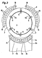
- La figure 3 est une vue partielle de dessus montrant l'assemblage d'un anneau, un seul plateau transporteur étant représenté.
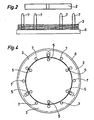
- La figure 4 est une vue de dessus de la station d'empilage.
- La figure 5 est une vue partielle de dessus d'un plateau transporteur avec un segment de tôle.
- La figure 5a est une vue en coupe selon la ligne Va-Va de la figure précédente.
- Figure 1 is a schematic representation of an installation for implementing the method comprising six different workstations.
- Figure 2 is a partial side view of the stacking station.
- Figure 3 is a partial top view showing the assembly of a ring, a single carrier plate being shown.
- Figure 4 is a top view of the stacking station.
- Figure 5 is a partial top view of a conveyor plate with a sheet metal segment.
- Figure 5a is a sectional view along line Va-Va of the previous figure.
Les figures 6, 6a et 7, 7a sont des vues analogues aux figures 5 et 5a montrant la prise en charge d'un segment par un organe de maintien.Figures 6, 6a and 7, 7a are views similar to Figures 5 and 5a showing the support of a segment by a holding member.
La figure 8 est une vue de côté et en coupe de certains éléments de la station de sertissage.Figure 8 is a side view in section of some elements of the crimping station.
L'installation complete de mise en oeuvre du procède illustrée à la figure 1 comprend six stations principales de travail dont les plus importantes sont la station d'empilage 1 et la station de sertissage VI.The complete installation for implementing the process illustrated in FIG. 1 comprises six main work stations, the most of which important are the stacking station 1 and the crimping station VI.
Les stations de travail de l'installation dans l'ordre du déroulement de la fabrication sont les suivantes: La station d'empilage I, la station de mesure Il de la hauteur d'un paquet partiel, les stations III d'empilage de tôles d'épaisseur D' inférieure à l'épaisseur D et IV pour l'empilage de tôles d'épaisseur D afin de compléter le paquet partiel par des couches d'épaisseur D'et/ou D suivant le résultat de mesure à la station II, la station V de centrage de segments et de mise en place de rivets et enfin la station VI de sertissage.The work stations of the installation in the order of the manufacturing process are as follows: The stacking station I, the station II for measuring the height of a partial package, the sheet metal stacking stations III with thickness D 'less than thickness D and IV for stacking sheets of thickness D in order to complete the partial package with layers of thickness D'and / or D depending on the measurement result at station II , the station V for centering segments and setting up rivets and finally the station VI for crimping.
Le travail d'empilage étant celui qui demande le plus grand temps, il est possible de prévoir une installation munie d'au moins deux stations d'empilage.Since the stacking job is the most time-consuming, it is possible to provide an installation provided with at least two stacking stations.
La station d'empilage 1 représentée tout à fait schématiquement comprend six magasins 1 a et 1b régulièrement répartis autour d'un plateau d'ajustement 2. Dans l'exemple choisi, les segments annulaires 3 ont une dimension angulaire de 120° et une épaisseur D. A l'exemple illustré les segments 3 représentés en traits mixtes ont été fournis par les magasins 1a et amenés par les plateaux transporteurs 4a qui sont représentes tout à fait schématiquement. Les magasins 1b, décalés de 60° par rapport aux magasins 1a, fourniront des segments 3 amenés par les plateaux 4b pour former une ou plusieurs couches de segments décalés de 60° par rapport aux segments fournis par les magasins 1a, afin de permettre, d'une part, d'assurer l'assemblage d'un paquet et d'autre part, de compenser les éventuelles erreurs de la valeur nominale de l'épaisseur des segments de tôle. Pour obtenir le décalage entre deux couches successives, on amène les segments de la première couche, par exemple, par les plateaux 4a, et de la suivante par les plateaux 4b. Les segments 3 sont tenus par les organes de maintien 5 faisant face aux magasins et plateaux transporteurs correspondants. Les éléments de la station d'empilage 1 seront décrits plus en détail à l'aide des figures 2 à 7a. Un dispositif transporteur amène un paquet de segments d'une hauteur H'< H, H étant la hauteur requise, à la station de mesure Il ou on mesure exactement la hauteur H' et ensuite le paquet passe aux stations III et IV comprenant, la première, trois magasins et trois plateaux transporteurs, et la seconde, six. Les magasins de la station III sont remplis de segments d'une épaisseur D'inférieure à D, alors que ceux de la station IV sont remplis des segments d'épaisseur D.The stacking station 1 shown quite diagrammatically comprises six
Selon le résultat de la mesure obtenue à la station Il, le paquet est complété par des couches de segments de la station III et/ou IV. A titre d'exemple, si on doit former un paquet de hauteur de 21 mm par des segments de tôles d'épaisseur de 1 mm, on forme à la station d'empilage 1 un paquet de dix-neuf couches, on amène le paquet à la station de mesure Il pour mesurer sa hauteur H' et ensuite le paquet passe aux stations III et IV où il est complété de sorte que sa hauteur soit la plus proche de 21 mm et surtout à l'intérieur des tolérances requises. Les segments de la station III ont par exemple une épaisseur D'=0,7 mm. En considérant les tolérances mentionnées précédemment, la hauteur du paquet doit être comprise entre (21-0,05) mm et (21 +0,55) mm et le choix du nombre de couches de segments de l'une ou de l'autre ou de toutes les deux stations III et IV est fait de sorte que la hauteur H reste à l'intérieur des tolérances requises. Si la hauteur mesurée H'=19,2 mm, alors il faut compléter le paquet par deux couches de 1 mm de la station IV et obtenir ainsi une hauteur de 21,2 mm qui est bien à l'intérieur des tolérances. De même si H'=19,4 mm on complètera par une couche de 0,7 mm de la station III et une couche de 1 mm de la station IV. Il faut souligner que les magasins et les plateaux transporteurs de la station sont au nombre de six de sorte que si deux couches sont déposées à la station IV, ces couches sont décalées de 60°.Depending on the result of the measurement obtained at station II, the packet is completed by layers of segments from station III and / or IV. For example, if we have to form a packet of
A la figure 2 on a représenté une vue partielle et de côté de la station d'empilage. On a notamment représenté le plateau d'ajustement 2 supportant les éléments de maintien 5, et en-dessous, le disque d'empilage 6 muni de six tiges de guidage 7 régulièrement réparties sur le disque 6. Chacun des anneaux 3 est guidé lors de sa chute par deux des tiges 7 qui s'engagent dans deux fentes espacées de 60°. La figure 4 est une vue de dessus de la figure 2. On a représenté en traits mixtes sur la figure 2 plusieurs couches de segments et sur la figure 4 on voit la couche supérieure.In Figure 2 there is shown a partial side view of the stacking station. There is in particular shown the
A la figure 3, on voit en traits pleins trois segments 3 d'un anneau amenés par des plateaux transporteurs 4a, dont un seul est représenté à la partie inférieure de la figure, vers le plateau d'ajustement 2. On a représenté sur la même figure schématiquement en traits mixtes les trois segments 3 maintenus par les trois organes de maintien 5 faisant face aux plateaux 4a avant que les plateaux transporteurs 4a se retirent. Le seul plateau transporteur 4a représenté à la figure 3 est monté sur une glissière et il est entraîné par un vérin à double effet. Son extrémité 8 se trouvant vers le plateau d'ajustement 2 a la forme d'un segment d'anneau de dimensions correspondant à celles d'un segment annulaire de tôle 3, formé dans un décrochement 9 du plateau 4a. Le décrochement 9 (fig. 5a, 6a, 7a) sert de butée à un segment annulaire de tôle 3 lors de sa prise en charge par le plateau transporteur 4a. L'extrémité annulaire 6 d'un plateau 4a ou 4b est munie à son milieu d'une encoche 10 de dimensions et forme correspondant à celles du corps 5a (qui sera decrit ultérieurement) d'un organe de maintien 5, faisant saillie radialement par rapport au plateau d'ajustement 2, afin de permettre au plateau transporteur 4a ou 4b d'amener le segment transporté 3 contre le plateau d'ajustement 2. L'encoche 10 se trouve au-dessous d'une fente 3a limitée par deux bras consécutifs 3b d'un segment d'anneau 3. La périphérie extérieure d'un segment est munie d'encoches 3c servant au centrage et guidage de segments 3 dans les magasins et sur les plateaux transporteurs.In FIG. 3, we see in solid lines three
La figure 5, représente une vue partielle d'un segment annulaire 3 pris en charge par un plateau transporteur 4a ou 4b. L'encoche 10 est visible entre deux bras consécutifs 3b du segment 3. Un aimant permanent peut être fixé dans un logement du plateau pour assurer la tenue du segment 3. On a représenté à la figure 5a en traits mixtes tout à fait schématiquement et en coupe un magasin 12 de segments de tôle 3. Le plateau transporteur recule jusqu'à ce que son extrémité présentant le décrochement 9 en forme d'anneau se trouve exactement sous le magasin 12, alors le segment inférieur de la pile tombe dans le décrochement 9 et le plateau 4a est poussé vers l'avant en direction du plateau d'ajustement 2 (fig. 6, 6a, 7, 7a) pour y amener le segment 3 et le cycle recommence.FIG. 5 represents a partial view of an
Aux figures 6 et 6a on a représenté un segment 3 à proximité du plateau d'ajustement 2. A la figure 6 on a representé uniquement une partie du plateau d'ajustement 2 avec un organe de maintien 5 et un segment 3, le plateau transporteur n'a pas été représenté. A la figure 6a on a présenté en coupe un plateau transporteur 4a, le segment 3 l'organe de maintien 5, le plateau d'ajustement 2 et un élément 13 assistant l'organe de maintien 5 qui sera décrit par la suite.In Figures 6 and 6a there is shown a
L'organe de maintien 5 présente un corps 5a faisant saillie par rapport au plateau d'ajustement 2 et formé de deux parties, une première partie prismatique 5'a dont la largeur est inférieure à la distance périphérique entre les extrémités de deux bras consécutifs 3b du segment 3, et une seconde partie cylindrique 5"a dont le diamètre est supérieur à la distance entre les extrémités des deux bras 3b consécutifs et inférieur à la distance entre les corps desdits bras. Cette seconde partie 5"a peut être également prismatique pour autant que sa largeur satisfasse aux mêmes conditions que le diamètre de la partie cylindrique. L'organe de maintien 5 est enfiché dans une encoche 2a approximativement cylindrique du plateau d'ajustement 2 par un corps 5b de forme et dimensions correspondant à celles de l'encoche 2a du plateau 2. La face supérieure de la partie cylindrique 5"a est inclinée, la partie la plus élevée se trouvant du côté de la partie prismatique 5'a et formant avec elle un décrochement 14.The holding
Lorsque le plateau transporteur 4a arrive à proximité du plateau d'ajustement 2, un élément plat 13 soumis à un effort vertical élastique plaque le segment 3 contre le plateau 4a et assiste sa prise en charge par l'organe de maintien 5. Quand le plateau 4a arrive contre le corps 5a les extrémités des deux bras 3b se trouvant au-dessous de l'encoche 10 du plateau transporteur 4a glissent sur la face inclinée de la partie 5"a et le segment 3 se trouve en position inclinée comme indiqué à la figure 6a. La pression exercée pendant ce temps par l'élément 13 assure le contact permanent du segment avec le plateau transporteur 4a et l'organe 5, et évite que le segment 3 quitte le plateau 4a. Lorsque les extrémités des bras 3b dépassent la face supérieure de la partie cylindrique 5"a, elles tombent dans le décrochement 14 de l'organe de maintien 5 et le segment 3 reprend sa position horizontale. La distance entre le point le plus élevé de la face superieure de la partie 5 a et la face d'appui de l'élément 13 doit être de l'ordre de 30 à 40 % de l'épaisseur d'un segment afin d'assurer le bon maintien du segment lors du recul du plateau transporteur. Le plateau transporteur 4a étant arrivé à la fin de sa course vers le plateau d'ajustement, est par la suite déplacé dans le sens contraire comme indiqué à la figure 7a mais le segment 3 ne peut pas le suivre car les extrémités des bras 3b viennent buter contre la partie cylindrique 5"a dont le diamètre est supérieur à leur distance. L'élément 13 assure d'ailleurs la tenue verticale du segment 3 pendant le recul du plateau 4a. Lorsque le plateau 4a n'est plus en contact avec le segment 3, ce dernier tombe verticalement sur le plateau d'empilage 6 guidé par les tiges 7. Il est évident que les mêmes opérations se font simultanément par les trois plateaux transporteurs 4a (respectivement 4b).When the
Pour assurer le décalage angulaire entre deux couches successives, on amène des segments, alternativement des magasins 1 a et 1 b, par les plateaux transporteurs 4a, respectivement 4b. Après avoir formé un paquet partiel de hauteur H', le disque d'empilage 6 est amené à la station de mesure Il et ensuite aux stations III et IV ou opèrent des plateaux transporteurs et des plateaux d'ajustement identiques à ceux décrits.To ensure the angular offset between two successive layers, segments, alternately
Selon une variante, pour compenser les erreurs d'épaisseur de segments de tôles influant sur le parallélisme du paquet, on fait tourner le disque d'empilage 6 trois fois d'un angle de 120°. La première rotation s'opère lorsque le tiers de la hauteur du paquet est atteint, ensuite les 2/3 et enfin une dernière fois avant l'évacuation du paquet lorsque H' est atteint. Bien sûr le nombre des rotations peut être supérieur à trois, mais de préférence un multiple entier de trois dans le cas présent, et d'une manière générale, un multiple entier de n, l'angle de rotation étant a.Alternatively, to compensate for errors in the thickness of sheet metal segments influencing the parallelism of the package, the stacking
Il est possible de former un anneau par un nombre supérieur de segments, par exemple six. Dans ce cas, les éléments de l'installation sont les mêmes que ceux décrits précédemment quant à leur structure, mais le nombre de magasins des plateaux transporteurs et organes de maintien doit être adapté au nombre de segments constituant un anneau.It is possible to form a ring by a greater number of segments, for example six. In this case, the elements of the installation are the same as those described above with regard to their structure, but the number of magazines of the transport trays and holding members must be adapted to the number of segments constituting a ring.
Après le passage du paquet de tôles par les stations II, III et IV, le paquet arrive à la station V, pour la mise en place de rivets. Les rivets, d'une seule pièce en fil d'acier doux, sont introduits dans les trous 15 (fig.3) des segments superposés qui forment ainsi des passages verticaux. Avant la mise en place des rivets le paquet est serré, entre deux coquilles ayant la forme d'un demi cylindre afin d'assurer un centrage approximatif du paquet.After the packet of sheets has passed through stations II, III and IV, the packet arrives at station V, for the installation of rivets. The rivets, in a single piece of mild steel wire, are introduced into the holes 15 (fig. 3) of the superimposed segments which thus form vertical passages. Before the establishment of the rivets the package is tightened, between two shells having the shape of a half cylinder to ensure approximate centering of the package.
Après la mise en place des rivets, le disque d'empilage est amené à la station de sertissage VI.After the establishment of the rivets, the stacking disc is brought to the crimping station VI.
A la figure 8 on a représenté une vue plus détaillée du disque d'empilage 6 et du dispositif de sertissage. Le disque d'empilage 6 est composé d'un plateau 16 dont la forme est cylindrique ou rectangulaire munie sur sa face inférieure de deux rainures 17 s'engageant sur deux rails correspondants du dispositif de transfert. Sur le plateau 16 est fixé un anneau 18 traversé par les tiges de guidage 7 (dont une seule est représentée ici), un second anneau amovible 19 muni de passages cylindriques pour les tiges de guidage 7 est suspendu sur le premier anneau 16 par des petits ressorts (non représentés). L'anneau 19 est muni, à la verticale des trous 15 des segments, d'orifices cylindriques 27 à l'intérieur desquels se trouvent des pointes dont la longueur est légèrement inférieure à celle des orifices 27. Les pointes sont munies à leur extrémité inférieure d'une tête les empêchant de sortir de l'anneau 19 en le traversant de bas en haut. Des vis 28, régulièrement réparties, sont vissées sur la face inférieure de l'anneau 19. Les vis 28 traversent librement (sans être vissées) l'anneau 18 tandis que leur tête 28a est logée dans un passage cylindrique du plateau 16 se trouvant à la verticale de l'une ou de l'autre des rainures 17.In Figure 8 there is shown a more detailed view of the stacking
Le dispositif de sertissage comprend essentiellement un moule 11, une quille 20 dont le rôle est de centrer les couches de segments par l'intérieur et par l'extérieur et d'assurer ainsi le respect des diamètres intérieur et extérieur du paquet de tôles se trouvant sur l'anneau 18 avant le sertissage, le moule et la quille étant assujettis à une presse 22. Entre le moule 11 et la quille 20 se trouve le dévêtisseur 21 représenté ici en deux positions extrêmes, position basse à droite de la figure 8 et position haute à gauche de la même figure. Le sertissage est réalisé de la manière suivante: la presse 22 fait descendre le moule 11 et la quille 20 sur le paquet de tôles 3 supporté par le disque d'empilage 6 décrit précédemment. Le dévêtisseur 21 en position basse entre en contact avec le paquet et au fur et à mesure de la descente de la presse, le moule 11 et la quille 20 centrent les couches successives de tôles, le dévêtisseur étant muni d'une série d'orifices 21a a pour le passage de tiges de guidage 7 et d'une série d'orifices 21b pour le passage des rivets et des pointes de sertissage 23. Le diamètre extérieur de la quille 20 et le diamètre intérieur du moule 11 correspondent exactement au diamètre intérieur, respectivement extérieur, du paquet de tôles choisi. Lorsque le dévêtisseur arrive vers la fin de sa course (position haute), il entre en contact avec des doigts 24 régulièrement répartis et se trouvant sous l'action des ressorts 25. Les doigts 24, sous l'action des ressorts 25, et l'anneau 18, sous l'action des vis 28, elles-mêmes soumises à l'effort des rampes à ressorts logés dans les rainures 17, compriment le paquet de tôles et centrent les rivets par rapport au paquet. Le centrage s'effectue d'un côté par les pointes 23 dans l'espace laissé libre dans les orifices 21 b du dévêtisseur en position haute, de l'autre côté dans les orifices cylindriques 27 de l'anneau 19 par les pointes correspondantes, lorsque les ressorts de suspension sont comprimés. Une fois le centrage des rivets réalisé, la presse 22 continue à descendre et le sertissage s'opère, les têtes de rivets étant de même grandeur des deux côtés du paquet. Les têtes supérieures sont obtenues par l'action des pointes 23 et les têtes inférieures par les pointes logées dans les orifices cylindriques 27 de l'anneau 19 du disque d'empilage 6. A la fin du sertissage, la presse remonte et le paquet est expulsé par la descente du dévêtisseur 21 sous l'action d'un effort vertical exercé par des tiges 26 entraînées par un vérin.The crimping device essentially comprises a
Avec une telle installation, le déposant a fabriqué des paquets de tôles d'une hauteur nominale de 21 mm en obtenant des paquets dont le défaut de parallélisme entre les deux faces du paquet est de 0,15 mm tandis que pour des paquets formés avec des anneaux fermés ce défaut est au minimum de 0,4 mm.With such an installation, the depositor has manufactured bundles of sheets with a nominal height of 21 mm by obtaining bundles whose lack of parallelism between the two faces of the bundle is 0.15 mm while for bundles formed with closed rings this defect is at least 0.4 mm.
L'assemblage des paquets de tôles peut être fait d'une autre manière, par exemple par soudage, mais avant celui-ci, il est absolument nécessaire de centrer le paquet de tôles avec un dispositif tel que décrit précédemment, muni d'un moule et d'une quille.The assembly of the sheet packs can be done in another way, for example by welding, but before this, it is absolutely necessary to center the sheet pack with a device as described above, provided with a mold and a keel.
Claims (16)
Applications Claiming Priority (2)
| Application Number | Priority Date | Filing Date | Title |
|---|---|---|---|
| FR8313104 | 1983-08-09 | ||
| FR8313104A FR2550478B1 (en) | 1983-08-09 | 1983-08-09 | METHOD FOR MANUFACTURING PACKETS OF MAGNETIC OR OTHER SHEETS OF ANNULAR FORM AND INSTALLATION FOR IMPLEMENTING SAME |
Publications (3)
| Publication Number | Publication Date |
|---|---|
| EP0136740A1 EP0136740A1 (en) | 1985-04-10 |
| EP0136740B1 true EP0136740B1 (en) | 1987-10-14 |
| EP0136740B2 EP0136740B2 (en) | 1991-09-18 |
Family
ID=9291516
Family Applications (1)
| Application Number | Title | Priority Date | Filing Date |
|---|---|---|---|
| EP84201144A Expired - Lifetime EP0136740B2 (en) | 1983-08-09 | 1984-08-06 | Process for manufacturing parcels of annular, magnetic or other plates and installation for carrying it out |
Country Status (6)
| Country | Link |
|---|---|
| US (1) | US4597172A (en) |
| EP (1) | EP0136740B2 (en) |
| CA (1) | CA1229721A (en) |
| DE (1) | DE3466841D1 (en) |
| ES (1) | ES8406247A1 (en) |
| FR (1) | FR2550478B1 (en) |
Cited By (1)
| Publication number | Priority date | Publication date | Assignee | Title |
|---|---|---|---|---|
| DE10013690B4 (en) * | 2000-03-21 | 2004-04-15 | Schuler Pressen Gmbh & Co. Kg | Process for the production of packages consisting of sheet metal parts |
Families Citing this family (14)
| Publication number | Priority date | Publication date | Assignee | Title |
|---|---|---|---|---|
| ATE70385T1 (en) * | 1986-05-22 | 1991-12-15 | Steinemann Ulrich Ag | METHOD AND DEVICE FOR LAYERING TIN PACKS, ESPECIALLY TRANSFORMER CORE. |
| US4882832A (en) * | 1987-02-02 | 1989-11-28 | Emerson Electric Co. | Method of manufacturing electric motor stator structure |
| FR2612703B1 (en) * | 1987-03-18 | 1994-01-07 | Ducellier Et Cie | METHOD FOR PRODUCING THE ALTERNATOR STATOR AND THE ALTERNATOR THUS OBTAINED |
| US4918831A (en) * | 1987-12-28 | 1990-04-24 | General Electric Company | Method of fabricating composite rotor laminations for use in reluctance, homopolar and permanent magnet machines |
| FR2631755A1 (en) * | 1988-03-02 | 1989-11-24 | Emiliane Trancerie Spa | METHOD FOR PRODUCING A MAGNETIC CIRCUIT FOR A STATOR OF ROTARY ELECTRIC MACHINES OR A MAGNETIC CIRCUIT FOR TRANSFORMERS, AND MAGNETIC CIRCUIT THUS OBTAINED |
| FR2641909B1 (en) * | 1989-01-19 | 1991-05-24 | Capemmo Umberto | METHOD OF MANUFACTURING A CAGE, OR STATOR OF A DYNAMO-ELECTRIC MACHINE, AND A CAGE OBTAINED ACCORDING TO THE METHOD |
| US5065497A (en) * | 1989-06-01 | 1991-11-19 | Westinghouse Electric Corp. | Apparatus for making a superconducting magnet for particle accelerators |
| US5098276A (en) * | 1989-06-01 | 1992-03-24 | Westinghouse Electric Corp. | Apparatus for making a superconducting magnet for particle accelerators |
| US5072516A (en) * | 1989-06-01 | 1991-12-17 | Westinghouse Electric Corp. | Apparatus and process for making a superconducting magnet for particle accelerators |
| US5088184A (en) * | 1989-06-01 | 1992-02-18 | Westinghouse Electric Corp. | Process for making a superconducting magnet for particle accelerators |
| US5065496A (en) * | 1989-06-01 | 1991-11-19 | Westinghouse Electric Corp. | Process for making a superconducting magnet coil assembly for particle accelerators |
| FR2800933B1 (en) * | 1999-11-10 | 2001-12-28 | Bourgeois R | PROCESS FOR THE MANUFACTURE OF PACKETS OF ANNULAR SHAPE SHEETS |
| US6484388B1 (en) * | 2000-08-10 | 2002-11-26 | Delphi Technologies, Inc. | Sequential roll-forming process for a stator |
| DE102004008567B4 (en) * | 2004-02-19 | 2013-08-01 | Volkswagen Ag | Device and method for producing an annular component having a plurality of segments in a plane |
Family Cites Families (9)
| Publication number | Priority date | Publication date | Assignee | Title |
|---|---|---|---|---|
| FR1335212A (en) * | 1962-07-26 | 1963-08-16 | Philips Nv | Device for the manufacture of packages made of identical flat metal plates, pierced with at least one hole, in particular for stators or rotors |
| GB1110594A (en) * | 1965-05-21 | 1968-04-18 | Elmasch Bau Sachsenwerk Dresde | Process and apparatus for production of stator and rotor plates for electrical machines |
| US3573129A (en) * | 1969-02-13 | 1971-03-30 | Emerson Electric Co | Stator core assembling apparatus |
| DE2629532A1 (en) * | 1975-07-03 | 1977-01-27 | Sev Alternateurs | METHOD AND DEVICE FOR A STATOR OR ROTOR OF AN ELECTRIC ROTATING MACHINE |
| US4080724A (en) * | 1976-01-13 | 1978-03-28 | Zephyr Wind Dynamo Company | Method of forming electrical machine care from E-laminations |
| US4079512A (en) * | 1976-06-03 | 1978-03-21 | Lakes Lee J | Core lamination selecting apparatus |
| DE2631188C3 (en) * | 1976-07-10 | 1979-11-29 | L. Schuler Gmbh, 7320 Goeppingen | Control circuit for a slot punching machine |
| DE3027987C2 (en) * | 1980-07-24 | 1984-08-16 | Maschinenfabrik Müller-Weingarten AG, 7987 Weingarten | Working method and device for the packaging of dynamo sheets broken down into circular ring segments |
| DE3174871D1 (en) * | 1981-03-31 | 1986-07-31 | Matsushita Electric Ind Co Ltd | Iron core laminate manufacturing apparatus |
-
1983
- 1983-08-09 FR FR8313104A patent/FR2550478B1/en not_active Expired
- 1983-12-07 ES ES527899A patent/ES8406247A1/en not_active Expired
-
1984
- 1984-07-30 US US06/635,421 patent/US4597172A/en not_active Expired - Lifetime
- 1984-07-31 CA CA000460118A patent/CA1229721A/en not_active Expired
- 1984-08-06 EP EP84201144A patent/EP0136740B2/en not_active Expired - Lifetime
- 1984-08-06 DE DE8484201144T patent/DE3466841D1/en not_active Expired
Cited By (1)
| Publication number | Priority date | Publication date | Assignee | Title |
|---|---|---|---|---|
| DE10013690B4 (en) * | 2000-03-21 | 2004-04-15 | Schuler Pressen Gmbh & Co. Kg | Process for the production of packages consisting of sheet metal parts |
Also Published As
| Publication number | Publication date |
|---|---|
| EP0136740B2 (en) | 1991-09-18 |
| CA1229721A (en) | 1987-12-01 |
| US4597172A (en) | 1986-07-01 |
| ES527899A0 (en) | 1984-08-01 |
| ES8406247A1 (en) | 1984-08-01 |
| DE3466841D1 (en) | 1987-11-19 |
| EP0136740A1 (en) | 1985-04-10 |
| FR2550478B1 (en) | 1986-05-23 |
| FR2550478A1 (en) | 1985-02-15 |
Similar Documents
| Publication | Publication Date | Title |
|---|---|---|
| EP0136740B1 (en) | Process for manufacturing parcels of annular, magnetic or other plates and installation for carrying it out | |
| EP2758327B1 (en) | Device for transferring pre-formed layers of objects to the top of a pallet | |
| EP2619118B1 (en) | Device for transporting bundles for a strapping machine | |
| CH686509A5 (en) | Stacker-returner device for printing machine-CUTTER called machine production of packaging boxes. | |
| EP0274969A2 (en) | Winding method for stators of electrical machines | |
| EP2250113B1 (en) | Device and method for preparing mandrels, device for collecting coiled mandrels, and device and method for handling mandrels | |
| WO2018069618A1 (en) | Device and method for removing a box from a chuck | |
| FR2475817A1 (en) | DEVICE FOR INSERTING PRE-WOUND COILS IN THE STATORS NOTCHES | |
| EP1335480B1 (en) | Method and device for producing a magnetic circuit for an electric motor | |
| EP1100185B1 (en) | Method of manufacture of annular shaped lamination stack | |
| FR2846481A1 (en) | METHOD AND DEVICE FOR INSERTING A WINDING IN A STATOR, WITH STRATIFICATION OF THE CHIGNON | |
| EP0050083B1 (en) | Apparatus for grouping unit-containers | |
| WO2016009137A1 (en) | Method for producing a wound stator of a rotary electric machine | |
| FR2568427A1 (en) | DYNAMOELECTRIC MACHINE, METHODS AND APPARATUSES FOR ASSEMBLING THE SAME. | |
| EP3526024A1 (en) | Method and device for shaping a blank around a mandrel | |
| CH658609A5 (en) | Machine for punching sheet metal | |
| FR2587311A1 (en) | Method and installation for automatic handling and temporary storage of stacked packets of semi-finished sheet products | |
| FR3089959A1 (en) | Method and device for handling flat and / or film material designed for packaging articles | |
| EP0040576A1 (en) | Method and handling apparatus for long products, especially tubes | |
| EP0236213A1 (en) | Automatic process for making coils without supporting frame and for mounting them on a printed circuit, and machine for carrying out the process | |
| EP0799488A1 (en) | Electrical winding with a low potential difference between adjacent turns | |
| CH470290A (en) | Grouping device for bodies of specific shape | |
| EP2414244B1 (en) | Installation and method for packaging components in the form of strips | |
| FR2523509A1 (en) | CIRCULAR MACHINE FOR THE AUTOMATIC MANUFACTURE OF PRESENTATION BOXES | |
| EP4311086A1 (en) | Device for producing a stack of metal sheets |
Legal Events
| Date | Code | Title | Description |
|---|---|---|---|
| PUAI | Public reference made under article 153(3) epc to a published international application that has entered the european phase |
Free format text: ORIGINAL CODE: 0009012 |
|
| AK | Designated contracting states |
Designated state(s): CH DE FR GB IT LI |
|
| 17P | Request for examination filed |
Effective date: 19850603 |
|
| 17Q | First examination report despatched |
Effective date: 19860711 |
|
| GRAA | (expected) grant |
Free format text: ORIGINAL CODE: 0009210 |
|
| ITF | It: translation for a ep patent filed |
Owner name: BUGNION S.P.A. |
|
| AK | Designated contracting states |
Kind code of ref document: B1 Designated state(s): CH DE FR GB IT LI |
|
| REF | Corresponds to: |
Ref document number: 3466841 Country of ref document: DE Date of ref document: 19871119 |
|
| GBT | Gb: translation of ep patent filed (gb section 77(6)(a)/1977) | ||
| PLBI | Opposition filed |
Free format text: ORIGINAL CODE: 0009260 |
|
| PLAB | Opposition data, opponent's data or that of the opponent's representative modified |
Free format text: ORIGINAL CODE: 0009299OPPO |
|
| 26 | Opposition filed |
Opponent name: KIENLE & SPIESS STANZ- UND DRUCKGIEBWERK GMBH Effective date: 19880714 |
|
| R26 | Opposition filed (corrected) |
Opponent name: KIENLE & SPIESS STANZ- UND DRUCKGIEBWERK GMBH Effective date: 19880811 |
|
| PUAH | Patent maintained in amended form |
Free format text: ORIGINAL CODE: 0009272 |
|
| STAA | Information on the status of an ep patent application or granted ep patent |
Free format text: STATUS: PATENT MAINTAINED AS AMENDED |
|
| ITTA | It: last paid annual fee | ||
| 27A | Patent maintained in amended form |
Effective date: 19910918 |
|
| AK | Designated contracting states |
Kind code of ref document: B2 Designated state(s): CH DE FR GB IT LI |
|
| ITF | It: translation for a ep patent filed |
Owner name: BUGNION S.P.A. |
|
| GBTA | Gb: translation of amended ep patent filed (gb section 77(6)(b)/1977) | ||
| REG | Reference to a national code |
Ref country code: GB Ref legal event code: IF02 |
|
| PGFP | Annual fee paid to national office [announced via postgrant information from national office to epo] |
Ref country code: DE Payment date: 20030618 Year of fee payment: 20 |
|
| PGFP | Annual fee paid to national office [announced via postgrant information from national office to epo] |
Ref country code: FR Payment date: 20030620 Year of fee payment: 20 |
|
| PGFP | Annual fee paid to national office [announced via postgrant information from national office to epo] |
Ref country code: GB Payment date: 20030806 Year of fee payment: 20 |
|
| PGFP | Annual fee paid to national office [announced via postgrant information from national office to epo] |
Ref country code: CH Payment date: 20030808 Year of fee payment: 20 |
|
| PG25 | Lapsed in a contracting state [announced via postgrant information from national office to epo] |
Ref country code: LI Free format text: LAPSE BECAUSE OF EXPIRATION OF PROTECTION Effective date: 20040805 Ref country code: GB Free format text: LAPSE BECAUSE OF EXPIRATION OF PROTECTION Effective date: 20040805 Ref country code: CH Free format text: LAPSE BECAUSE OF EXPIRATION OF PROTECTION Effective date: 20040805 |
|
| REG | Reference to a national code |
Ref country code: GB Ref legal event code: PE20 |
|
| REG | Reference to a national code |
Ref country code: CH Ref legal event code: PL |