EP0136372B1 - Removable money container actuated by a cash register - Google Patents
Removable money container actuated by a cash register Download PDFInfo
- Publication number
- EP0136372B1 EP0136372B1 EP83109984A EP83109984A EP0136372B1 EP 0136372 B1 EP0136372 B1 EP 0136372B1 EP 83109984 A EP83109984 A EP 83109984A EP 83109984 A EP83109984 A EP 83109984A EP 0136372 B1 EP0136372 B1 EP 0136372B1
- Authority
- EP
- European Patent Office
- Prior art keywords
- base plate
- register
- cassette
- bottom part
- cash
- Prior art date
- Legal status (The legal status is an assumption and is not a legal conclusion. Google has not performed a legal analysis and makes no representation as to the accuracy of the status listed.)
- Expired
Links
Images


Classifications
-
- G—PHYSICS
- G07—CHECKING-DEVICES
- G07G—REGISTERING THE RECEIPT OF CASH, VALUABLES, OR TOKENS
- G07G1/00—Cash registers
- G07G1/0018—Constructional details, e.g. of drawer, printing means, input means
- G07G1/0027—Details of drawer or money-box
Definitions
- the invention relates to a portable cash register-controlled cash cassette with a lockable cassette flap, the cassette base being assigned a cash register lock which opens the cassette flap in its first position.
- the cash drawers customary in cash registers have the disadvantage that they obstruct the operator when they are extended, since they have to step back a little each time the drawer is opened, which is particularly annoying when the operator is seated. Because of the required space under the cash register or under the cash desk when the operator is seated, the keyboard of the cash register for the arm posture comes to an unfavorable height when the cash drawer has to be arranged under the cash register. For this reason, the cash drawer has already been installed on the side of the cash register next to the cash register. However, this again has the disadvantage that arm movements in the lateral direction over longer distances are required when operating the keyboard and the cash drawer. More favorable conditions arose in the case of a cash cassette which has now been proposed and which is arranged immediately in front of the cash register, extends over the entire width of the cash register at a relatively shallow depth and is closed off by a hinged lid.
- EP-A-0014856 has already disclosed a container for banknotes and cash which can be provided with a lockable cassette flap and can be accommodated separately from the cash register.
- the disadvantage of this cassette is that the electrical connections to the electromagnetically controlled opening device must be disconnected to remove the container for transport. In addition, the container is not secured against theft in its operating position.
- the container for receiving and storing banknotes according to DE-A-30 37 516 is provided with a lock for securing the cover and another lock for theft-proof connection with a receiving frame arranged in the table top.
- This container is only an additional device to the cash drawers customary in cash registers and is used to store the banknotes that are no longer required as change.
- the object of the invention is to design the known cash register-controlled cash cassette in such a way that it is secured against theft in the operating position and can be removed from the cash register without detaching electrical connections.
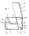
- the cash cassette (FIGS. 1 to 3) essentially consists of a cassette base part 1, the cassette flap 7 and a locking and locking device accommodated in a closed chamber 4 of the cassette base part 1, which together with devices on a base plate will be referred to below with reference to FIGS. 4 to 9 is explained in more detail.
- the molded plastic base part 1 is with two bill compartments 2 and 3 (Fig. 2 and 3) for the horizontal stacking of z. B. DM 50, - and DM 100, notes equipped, which are on both sides of the chamber 4 arranged in the middle.
- Both bill compartments 2 and 3 are each covered by a removable coin insert 5 and 6 in such a way that sufficiently wide and deep openings 8 and 9 are formed towards the front of the operator, which allow the depositing and removal of the banknotes.
- Both coin inserts have three coin trays 11 to 13 or 14 to 16, the middle coin tray 12 or 15 being set back somewhat in order to widen the openings 8 and 9 in the central region for better handling.
- the base part 1 of the cassette has two recesses 22 (FIG. 1) on the lower edge of its rear wall, each of which has an associated hook 23a of a base plate 23.
- the base plate 23 has at its rear edge a perpendicular upward bend 23b against which the base of the cassette is supported with its rear wall in the attached state.
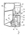
- a vertical hook 23c (FIG. 9) which is used to lock the cassette serves on the base plate 23, which is embedded in a suitable place in front of or to the side of the cash register in the table top of a cash desk gondola or on a sales table or the like.
- Four bearing points 24 to 27 (FIGS.
- the cassette flap 7 is provided on its sides with a stop 30, preferably made of rubber, in order to dampen the impact noise when closing.
- a padded hand rest pad 31 is glued, which is provided with a slot 32 in which received bills can be visibly stored until they are finally deposited after the checkout process has been completed.
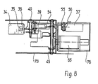
- a cranked tab 34 (FIG. 5) is fastened to the cassette flap 7, and a web 36 is formed at the lower end of this by punching out a hole 35.
- this web 36 lies in the fork 38 of a locking lever 39 which is rotatably mounted on a pin 40 and is supported with its edge 41 on a stop surface 43 of a pawl 44.
- the U-shaped pawl 44 is rotatably mounted on a bearing pin 45 and is non-positively pulled into its basic position (FIG. 5) by a tension spring 46 (FIG. 9). By lifting the leg 47 of the pawl 44, it is pivoted clockwise, so that its stop surface 43 releases the edge 41 of the locking lever 39.
- the locking lever 39 pulled by its tension spring 48 and supported by the two torsion springs 28 and 29, can pivot clockwise at the bearing points of the cassette flap 7 until the web 36 of the tab 34 out of the fork 38a (dashed position of the fork 38) slides and the stop edge 49 of a side arm of the locking lever 39 on a rubber roller 50 on a pin 51 comes to rest.
- the cassette flap 7 can open under the action of the torsion springs 28 and 29.
- the switch lever 54 (FIG. 4) which moves the switch pin 56 of the switch 57 via a lever 55 is moved to the left by a pin 53 mounted in the locking lever 39.
- This switch 57 can be used to indicate to a cash register or the like, if any, that the cash cassette is open or closed.
- the above-mentioned lifting of the leg 47 of the pawl 44 takes place by actuating a lock 60 (FIG. 6) arranged on the front edge of the base part 1 of the cassette in a first working position “opening the cassette flap •, by means of which a lock lever 61 (FIGS. 6 and 7 ) is pivoted, the first bend 62 lifts the leg 47 when the lock is turned in the direction of the arrow 63 and thus causes the cassette flap 7 to open.
- the opening of the cassette door 7 can also be triggered by an electrical pulse.
- a magnet 65 (FIG.
- the time in which the pawl 44 is in its open position is also very short. During this time, if the cassette door 7 is in its opening movement by e.g. an unintentional hand load or the like is hindered, a subsequent opening of the cassette flap is no longer possible because the pawl 44 has already moved back to its basic position (FIGS. 4 and 5) and locks the locking lever 39 again. In this case, the checkout process could not be ended.
- an additional pawl 70 (FIG. 9) rotatably mounted on the pin 40 is provided, which holds a leg 72 of the magnetic lever 68 in its open position 72a (dashed line in FIG. 9) with its nose 71. Only shortly before the end of the rotary movement, which the locking lever 39 executes when the cassette flap 7 is opened, does the pin 53 (FIGS. 5 and 9) hit the pawl 70 (FIG. 9, pin 53a) and pivots it a short movement in the clockwise direction until the nose 71 releases the leg 72 of the magnetic lever 68 again. The magnetic lever 68 and the pawl 44 fall back into their basic position and the cassette flap 7 can be closed again.
- the aforementioned vertical hook 23c in the front region of the base plate 23 projects into the chamber 4 or the housing 73 (FIG. 4) when the cash cassette is attached, where it serves as a support for the leg 72 of the magnetic lever 68 (FIG. 9).
- the lock 60 In the basic position of the lock 60 there is a second bend 77 of the lock lever 61 under the hook 23c of the base plate 23, so that the cash box can no longer be removed.
- the second bend 77 is pivoted out of the hook 23c and the cash cassette is unlocked.
- the cash cassette can now be raised on its front side, pulled forward from the rear hooks 23a and lifted off the base plate 23 and placed in a safe for storage, for example.
- the mechanical part of the locking device (FIGS. 4, 6, 8 and 9) with the locking lever 39, the pawl 44, the switch lever 54, the lock 60 with the lock lever 61 and the associated bearing pins 40, 45, 51, 53 and tension springs 46 , 48 is housed in a housing 73 with hooks 74 and two screws 75 in the chamber 4 of the base part 1 of the cassette, while the magnet 65 is fastened in a contact-safe manner in a further housing 76 on the base plate 23, which is fixed in place on the cash desk table of the cash register nacelle or the like.
- the base plate 23 is fastened to the cash desk or the like by a plurality of fastening screws 79. These fastening screws are not accessible when the cash cassette is attached. Disassembly is only possible with the cassette removed. This provides additional theft protection.
Abstract
Description
Die Erfindung betrifft eine transportable registrierkassengesteuerte Geldkassette mit einer abschließbaren Kassettenklappe, wobei dem Kassettengrundteil ein Kassenschloß zugeordnet ist, das in seiner ersten Stellung die Kassettenklappe öffnet.The invention relates to a portable cash register-controlled cash cassette with a lockable cassette flap, the cassette base being assigned a cash register lock which opens the cassette flap in its first position.
Die bei Registrierkassen üblichen Geldschubladen haben den Nachteil, daß sie beim Ausfahren die Bedienungsperson behindern, da sie jeweils beim Öffnen der Schublade etwas zurücktreten muß, was bei sitzender Bedienung besonders störend ist. Wegen des erforderlichen Platzbedarfs unter der Registrierkasse bzw. unter dem Kassentisch bei sitzender Bedienung kommt die Tastatur der Registrierkasse für die Armhaltung in eine ungünstige Höhenlage, wenn die Geldschublade unter der Registrierkasse angeordnet werden muß. Man hat aus diesem Grunde schon die Geldschublade seitlich neben der Registrierkasse in den Kassentisch eingebaut. Hierbei ergibt sich aber wieder der Nachteil, daß bei der Bedienung der Tastatur und der Geldschublade Armbewegungen in seitlicher Richtung über größere Strecken erforderlich sind. Günstigere Bedingungen ergaben sich bei einer inzwischen vorgeschlagenen Geldkassette, die unmittelbar vor der Registrierkasse angeordnet wird, sich bei verhältnismäßig geringer Tiefe über die gesamte Breite der Registrierkasse erstreckt und durch einen Klappdeckel abgeschlossen ist.The cash drawers customary in cash registers have the disadvantage that they obstruct the operator when they are extended, since they have to step back a little each time the drawer is opened, which is particularly annoying when the operator is seated. Because of the required space under the cash register or under the cash desk when the operator is seated, the keyboard of the cash register for the arm posture comes to an unfavorable height when the cash drawer has to be arranged under the cash register. For this reason, the cash drawer has already been installed on the side of the cash register next to the cash register. However, this again has the disadvantage that arm movements in the lateral direction over longer distances are required when operating the keyboard and the cash drawer. More favorable conditions arose in the case of a cash cassette which has now been proposed and which is arranged immediately in front of the cash register, extends over the entire width of the cash register at a relatively shallow depth and is closed off by a hinged lid.
Durch die EP-A-0014856 ist bereits ein Behälter für Wertscheine und Hartgeld bekannt geworden, der mit einer verschließbaren Kassettenklappe versehen und getrennt von der Registrierkasse untergebracht werden kann. Nachteilig ist bei dieser Kassette, daß zur Entnahme des Behälters zum Transport die elektrischen Anschlüsse zur elektromagnetisch gesteuerten Öffnungsvorrichtung gelöst werden müssen. Außerdem ist der Behälter in seiner Betriebslage nicht gegen Diebstahl gesichert.EP-A-0014856 has already disclosed a container for banknotes and cash which can be provided with a lockable cassette flap and can be accommodated separately from the cash register. The disadvantage of this cassette is that the electrical connections to the electromagnetically controlled opening device must be disconnected to remove the container for transport. In addition, the container is not secured against theft in its operating position.
Der Behälter zur Aufnahme und Aufbewahrung von Geldscheinen gemäß der DE-A-30 37 516, ist mit einem Schloß zur Sicherung des Deckels und einem weiteren Schloß zur diebstahlsicheren Verbindung mit einem in der Tischplatte angeordneten Aufnahmerahmen versehen. Dieser Behälter ist lediglich eine Zusatzeinrichtung zu den bei Registrierkassen üblichen Geldschubladen und dient zur Aufbewahrung der als Wechselgeld nicht mehr benötigten Geldscheine.The container for receiving and storing banknotes according to DE-A-30 37 516 is provided with a lock for securing the cover and another lock for theft-proof connection with a receiving frame arranged in the table top. This container is only an additional device to the cash drawers customary in cash registers and is used to store the banknotes that are no longer required as change.
Der Erfindung liegt die Aufgabe zugrunde, die bekannte registrierkassengesteuerte Geldkassette so auszubilden, daß sie in der Betriebslage gegen Diebstahl gesichert ist und ohne elektrische Verbindungen zu lösen von der Registrierkasse abgenommen werden kann.The object of the invention is to design the known cash register-controlled cash cassette in such a way that it is secured against theft in the operating position and can be removed from the cash register without detaching electrical connections.
Die gestellte Aufgabe wird durch die im kennzeichnenden Teil des Patentanspruchs 1 angegebenen Merkmale gelöst. Weitere vorteilhafte Ausbildungen der Erfindung sind in den Unteransprüchen angegeben.The object is achieved by the features specified in the characterizing part of patent claim 1. Further advantageous developments of the invention are specified in the subclaims.
Ein Ausführungsbeispiel der Erfindung wird nun anhand der Zeichnungen im einzelnen erläutert. Es zeigen :
- Figur 1 eine Seitenansicht der Geldkassette, geschnitten (Schnittlinie I-I in Fig. 3),
Figur 2 eine Frontansicht, teilweise geschnitten (Schnittlinie II-II in Fig. 3),Figur 3 eine Draufsicht auf die offene Geldkassette, Deckel, aufgeklappt, geschnitten,Figur 4 einen Querschnitt durch die Geldkassette (Schnittlinie IV-IV in Fig. 3).Figur 5 einen Querschnitt durch einen Teil der Geldkassette (Schnittlinie V-V in Fig. 3),Figur 6 eine Einzelheit zum Schloß (Seitenansicht),Figur 7 eine Einzelheit zum Schloß (Rückansicht),- Figur 8 eine Teilansicht der Verriegelungseinrichtung, teilweise geschnitten und
Figur 9 eine weitere Teilansicht der Verriegelungs-einrichtung
- 1 shows a side view of the cash box, sectioned (section line II in FIG. 3),
- FIG. 2 shows a front view, partly in section (section line II-II in FIG. 3),
- FIG. 3 shows a plan view of the open cash cassette, cover, opened, cut,
- Figure 4 shows a cross section through the cash box (section line IV-IV in Fig. 3).
- FIG. 5 shows a cross section through part of the cash cassette (section line VV in FIG. 3),
- FIG. 6 shows a detail of the castle (side view),
- FIG. 7 shows a detail of the castle (rear view),
- Figure 8 is a partial view of the locking device, partially cut and
- Figure 9 is another partial view of the locking device
Die Geldkassette (Fig. 1 bis 3) besteht im wesentlichen aus einem Kassettengrundteil 1, der Kassettenklappe 7 und einer in einer geschlossenen Kammer 4 des kassettengrundteils 1 untergebrachten Schloß- und Verriegelungseinrichtung, die zusammen mit Vorrichtungen an einer Grundplatte nachstehend anhand der Fig. 4 bis 9 näher erläutert wird.The cash cassette (FIGS. 1 to 3) essentially consists of a cassette base part 1, the
Das aus Kunststoff gespritzte Kassettengrundteil 1 ist mit zwei Geldscheinfächern 2 und 3 (Fig. 2 und 3) für die liegende Stapelung von z. B. DM 50, - und DM 100, -Scheinen ausgestattet, die beiderseits der in der Mitte angeordneten Kammer 4 liegen. Beide Geldscheinfächer 2 und 3 werden je durch einen herausnehmbaren Münzeinsatz 5 und 6 so abgedeckt, daß nach vorn zur Bedienungsperson genügend breite und tiefe Öffnungen 8 und 9 gebildet werden, die das Ablegen- und Herausnehmen der Geldscheine zulassen. Beide Münzeinsätze weisen drei Münzschalen 11 bis 13 bzw. 14 bis 16 auf, wobei die jeweils mittlere Münzschale 12 bzw. 15 etwas zurückgesetzt ist, um die Öffnungen 8 und 9 im mittleren Bereich zur besseren Handhabung zu verbreitern.The molded plastic base part 1 is with two
Hinter den Münzeinsätzen 5 und 6 sind zwei weitere Geldscheinfächer 18 und 19 (Fig. 3) für stehende Stapelung von DM 10, - und DM 20, - Scheinen und zwischen ihnen zwei weitere Münzschalen 20 und 21 angeordnet.Behind the coin inserts 5 and 6, two
Das Kassettengrundteil 1 besitzt an der Unterkante seiner Rückwand zwei Aussparungen 22 (Fig. 1) in die je ein zugeordneter Haken 23a einer Grundplatte 23 fassen. Die Grundplatte 23 besitzt an ihrer rückwärtigen Kante eine senkrecht nach oben stehende Abwinkelung 23b gegen die sich das Kassettengrundteil mit seiner Rückwand im aufgesetzten Zustand abstüzt. Im vorderen Bereich der waagerechten Grundplatte 23 ist ein senkrecht stehender Haken 23c (Fig. 9) angeordnet, der zur Verriegelung der Kassette auf der Grundplatte 23 dient, die an geeigneter Stelle vor oder seitlich der Registrierkasse eingelassen in die Tischplatte einer Kassengondel oder auf einem Verkaufstisch oder dergl. befestigt ist. An der oberen Kante der Rückwand des Kassettengrundteils 1 sind vier Lagerstellen 24 bis 27 (Fig. 1 und 3) für die Lagerung der Kassettenklappe 7 angeordnet. Zwei Drehfedern 28 und 29, die in die Lagerstellen 25 und 26 eingebaut sind, öffnen die Kassettenklappe 7 selbsttätig, sobald sie entriegelt wird. Die Federrate ist dabei so ausgelegt, daß sich bei einer Klappenöffnung von ca. 60° das Drehmoment der Klappe, hervorgerufen durch das Klappengewicht, mit dem gemeinsamen Drehmoment der beiden Drehfedern 28 und 29 im Gleichgewicht befindet.The base part 1 of the cassette has two recesses 22 (FIG. 1) on the lower edge of its rear wall, each of which has an associated hook 23a of a
Die Kassettenklappe 7 ist an ihren Seiten mit je einem vorzugsweise aus Gummi bestehenden Anschlag 30 versehen, um das Aufschlaggeräusch beim Schließen zu dämpfen.The
Auf die Kassettenklappe 7 ist ein gepolstertes Handauflagekissen 31 geklebt, das mit einem Schlitz 32 versehen ist, in dem entgegengenommene Geldscheine bis zu ihrer endgültigen Ablage nach Abschluß des Kassiervorganges sichtbar aufbewahrt werden können.On the
An der Kassettenklappe 7 ist eine gekröpfte Lasche 34 (Fig. 5) befestigt, an deren unterem Ende durch Ausstanzen eines Loches 35 ein Steg 36 entstanden ist. Bei geschlossener Kassettenklappe 7 liegt dieser Steg 36 in der Gabel 38 eines Riegelhebels 39, welcher auf einem Stift 40 drehbar gelagert ist und sich mit seiner Kante 41 auf einer Anschlagfläche 43 einer Klinke 44 ab- ,stützt. Die U-förmig gebogene Klinke 44 ist auf einem Lagerbolzen 45 drehbar gelagert und wird durch eine Zugfeder 46 (Fig. 9) kraftschlüssig in seine Grundstellung (Fig. 5) gezogen. Durch Anheben des Schenkels 47 der Klinke 44 wird diese im Uhrzeigerdrehsinn verschwenkt, so daß ihre Anschlagfläche 43 die Kante 41 des Riegelhebels 39 freigibt. Jetzt kann sich der Riegelhebel 39, gezogen durch seine Zugfeder 48 und unterstützt durch die beiden Drehfedern 28 und 29, an den Lagerstellen der Kassettenklappe 7 im Uhrzeigerdrehsinn verschwenken, bis der Steg 36 der Lasche 34 aus der Gabel 38a (gestrichelte Stellung der Gabel 38) gleitet und die Anschlagkante 49 eines Seitenarms des Riegelhebels 39 an einer Gummirolle 50 auf einem Stift 51 zur Anlage kommt. Sowie die Gabel 38a den Steg 36 der Lasche 34 freigegeben hat, kann sich die Kassetenklappe·7 unter Wirkung der Drehfedern 28 und 29 öffnen. Gleichzeitig wird durch einen im Riegelhebel 39 gelagerten Stift 53 der Schalterhebel 54 (Fig. 4) nach links bewegt, der über einen Hebel 55 den Schaltstift 56 des Schalters 57 betätigt. Durch diesen Schalter 57 kann einer gegebenenfalls augeschlossenen Registrierkasse oder dergleichen der geöffnete bzw. geschlossene Zustand der Geldkassette angezeigt werden.A cranked tab 34 (FIG. 5) is fastened to the
Das oben erwähnte Anheben des Schenkels 47 der Klinke 44 erfolgt durch die Betätigung eines an der Vorderkante des Kassettengrundteils 1 angeordneten Schlosses 60 (Fig. 6) in eine erste Arbeitsstellung « Öffnen der Kassettenklappe •, durch das ein Schloßhebel 61 (Fig. 6 und 7) verschwenkt wird, dessen erste Abwinkelung 62 bei einer Schloßdrehung in Richtung des Pfeiles 63 den Schenkel 47 anhebt und damit das Öffnen der Kassettenklappe 7 bewirkt. Das Öffnen der Kassettenklappe 7 kann aber auch durch einen elektrischen Impuls ausgelöst werden. Hierzu ist ein auf der Grundplatte 23 angeordneter Magnet 65 (Fig. 9) vorgesehen, dessen Stoßstange 66 bei Erregung des Magneten 65 über eine Abwinkelung 67 eines auf dem Lagerbolzen 45 drehbar gelagerten Magnethebels 68 den Schenkel 47 der Klinke 44 im Uhrzeigerdrehsinn verschwenkt, wodurch die Kassettenklappe 7 geöffnet wird, wie oben beschrieben ist.The above-mentioned lifting of the
Da der Stromimpuls für den Magneten 65 verhältnismäßig kurz ist, ist auch die Zeit, in der sich die Klinke 44 in ihrer Öffnungsposition befindet, sehr kurz. Wenn die Kassettenklappe 7 während dieser Zeit an ihrer Öffnungsbewegung durch z.B. eine unbeabsichtigte Handbelastung oder dergleichen behindert wird, ist ein nachträgliches Öffnen der Kassettenklappe nicht mehr möglich, da sich die Klinke 44 bereits in ihre Grundstellung (Fig. 4 und 5) zurückbewegt hat und den Riegelhebel 39 wieder sperrt. In diesem Fall könnte der Kassiervorgang nicht beendet werden.Since the current pulse for the
Um diese Möglichkeit zu verhindern, ist eine zusätzliche auf dem Stift 40 drehbar gelagerte Klinke 70 (Fig. 9) vorgesehen, die mit ihrer Nase 71 einen Schenkel 72 des ',iagnethebels 68 in seiner Öffnungsposition 72a (gestrichelt in Fig. 9) festhält. Erst kurz vor dem Ende der Drehbewegung, die der Riegelhebel 39 beim Öffnen der Kassettenklappe 7 ausführt, trifft der Stift 53 (Fig. 5 und 9) auf die Klinke 70 (Fig. 9, Stift 53a) und schwenkt diesen eine kurze Bewegung im Uhrzeigerdrehsinn, bis die Nase 71 den Schenkel 72 des Magnethebels 68 wieder freigibt. Der Magnethebel 68 und die Klinke 44 fallen in ihre Grundposition zurück und die Kassettenklappe 7 kann wieder geschlossen werden.In order to prevent this possibility, an additional pawl 70 (FIG. 9) rotatably mounted on the
Der bereits erwähnte senkrecht stehende Haken 23c im vorderen Bereich der Grundplatte 23 ragt bei aufgesetzter Geldkassette in die Kammer 4 bzw. das Gehäuse 73 (Fig. 4) hinein, wo er dem Schenkel 72 des Magnethebels 68 als Abstützung dient (Fig. 9). In der Grundstellung des Schlosses 60 liegt eine zweite Abwinkelung 77 des Schloßhebels 61 unter dem Haken 23c der Grundplatte 23, so daß die Geldkassette nicht mehr abgenommen werden kann. Durch Drehen des Schlosses 60 in eine zweite Arbeitsstellung « Entnahme der Geldkassette » wird die zweite Abwinkelung 77 aus dem Haken 23c herausgeschwenkt und die Geldkassette entriegelt. Die Geldkassette kann nun an ihrer Vorderseite angehoben, von den rückwärtigen Haken 23a nach vorn abgezogen und von der Grundplatte 23 abgehoben und beispielsweise zur Aufbewahrung in einen Safe gebracht werden.The aforementioned
Beim Abnehmen der Geldkassette bewegt sich der Magnethebel 68 mit seinem Schenkel 72 in seine Öffnungsposition 72a (Fig. 7) und wird in Grundstellung des Schlosses 60 von den beiden Abwinkelungen 62 und 77 des Schloßhebels 61 in seinen Bewegungen begrenzt. Gleichzeitig werden die Löcher im Gehäuse 73 für den Haken 23c der Grundplatte 23 und für die Stoßstange 66 des Magneten 65 von der zweiten Abwinkelung 77, dem Schenkel 72 und der Abwinkelung 67 des Magnethebels 68 abgedeckt, so daß Manipulationen zum widerrechtlichen Öffnen der Kassettenklappe 7 ausgeschlossen sind.When you remove the cash box, it moves the
Der mechanische Teil der Verriegelungseinrichtung (Fig. 4, 6, 8 und 9) mit dem Riegelhebel 39, der Klinke 44, dem Schalterhebel 54, dem Schloß 60 mit dem Schloßhebel 61 und die zugehörigen Lagerstifte 40, 45, 51, 53 und Zugfedern 46, 48 ist in einem Gehäuse 73 mit Haken 74 und zwei Schrauben 75 in der Kammer 4 des Kassettengrundteils 1 untergebracht, während der Magnet 65 mit dem Schalter 57 berührungssicher in einem weiteren Gehäuse 76 auf der Grundplatte 23 befestigt ist, die ortsfest am Kassentisch der Kassengondel oder dergl. eingebaut ist. Diese Trennung des mechanischen vom elektrischen Teil des Entriegelungsmechanismusses erlaubt ein einfaches Abnehmen der Geldkassette von der Grundplatte 23 unter Beibehaltung der Schloßfunktion « Öffnen der Kassettenklappe und « Entnahme der Geldkassette ohne jedoch die elektrische Verbindung zwischen Magnet/Schalter und der zugehörigen Registrierkasse zu lösen.The mechanical part of the locking device (FIGS. 4, 6, 8 and 9) with the locking
Die Grundplatte 23 ist durch mehrere Befestigungsschrauben 79 auf dem Kassentisch oder dergl. befestigt. Bei aufgesetzter Geldkassette sind diese Befestigungsschrauben nicht zugänglich. Eine Demontage ist also nur bei abgenommener Kassette möglich. Hierdurch ist eine weitere Diebstahlsicherung gegeben.The
Der besondere Vorteil der Geldkassette gemäß der Anmeldung ist darin zu sehen, daß neben den günstigen ergonomischen Verhältnissen, die mit dieser Geldkassette gegeben sind, der Ablösungsvorgang der Kassenbedienung durch einfaches Auswechseln der personengebundenen Geldkassette zeitlich auf ein Minimum verkürzt wird.The particular advantage of the cash cassette according to the application can be seen in the fact that, in addition to the favorable ergonomic conditions that are present with this cash cassette, the cashier operation replacement process is reduced to a minimum by simply replacing the personal cash cassette.
Claims (4)
Priority Applications (2)
| Application Number | Priority Date | Filing Date | Title |
|---|---|---|---|
| EP83109984A EP0136372B1 (en) | 1983-10-06 | 1983-10-06 | Removable money container actuated by a cash register |
| AT83109984T ATE22185T1 (en) | 1983-10-06 | 1983-10-06 | PORTABLE CASH CASH BOX. |
Applications Claiming Priority (1)
| Application Number | Priority Date | Filing Date | Title |
|---|---|---|---|
| EP83109984A EP0136372B1 (en) | 1983-10-06 | 1983-10-06 | Removable money container actuated by a cash register |
Publications (2)
| Publication Number | Publication Date |
|---|---|
| EP0136372A1 EP0136372A1 (en) | 1985-04-10 |
| EP0136372B1 true EP0136372B1 (en) | 1986-09-10 |
Family
ID=8190724
Family Applications (1)
| Application Number | Title | Priority Date | Filing Date |
|---|---|---|---|
| EP83109984A Expired EP0136372B1 (en) | 1983-10-06 | 1983-10-06 | Removable money container actuated by a cash register |
Country Status (2)
| Country | Link |
|---|---|
| EP (1) | EP0136372B1 (en) |
| AT (1) | ATE22185T1 (en) |
Cited By (3)
| Publication number | Priority date | Publication date | Assignee | Title |
|---|---|---|---|---|
| DE4207589C1 (en) * | 1992-03-10 | 1993-04-01 | Siemens Nixdorf Informationssysteme Ag, 4790 Paderborn, De | |
| DE102005046909B4 (en) * | 2005-09-30 | 2013-04-04 | Anker Systems Gmbh | Device for locking and unlocking the lid of a cash register-controlled cashbox |
| DE102015122110A1 (en) | 2015-12-17 | 2017-06-22 | Werner Ulbts | Security system and method for opening a lock |
Families Citing this family (6)
| Publication number | Priority date | Publication date | Assignee | Title |
|---|---|---|---|---|
| DE19743691C1 (en) * | 1997-10-02 | 1999-01-14 | Siemens Nixdorf Inf Syst | Cover locking arrangement for money tray of cash register |
| DE19839977A1 (en) * | 1998-09-02 | 2000-03-09 | Siemens Nixdorf Inf Syst | Cash box arrangement |
| EP1067494B1 (en) * | 1999-07-03 | 2001-08-22 | Anker Systems GmbH | Cash register drawer with trigger attached to drawer housing |
| DE10255118B4 (en) * | 2002-11-26 | 2006-11-16 | Wincor Nixdorf International Gmbh | Locking device for locking the lid of a cash drawer to a Kassenladenunterteil |
| JP4617709B2 (en) * | 2004-04-28 | 2011-01-26 | セイコーエプソン株式会社 | Case and printer with locking mechanism |
| CN104036587B (en) * | 2014-06-30 | 2016-05-11 | 广州广电运通金融电子股份有限公司 | A kind of portable drum-type paper money case and a kind of ATM |
Family Cites Families (4)
| Publication number | Priority date | Publication date | Assignee | Title |
|---|---|---|---|---|
| WO1979000514A1 (en) * | 1978-01-18 | 1979-08-09 | Chubb Electronics Ltd | Cash registers |
| DE2907801C2 (en) * | 1978-02-28 | 1985-10-31 | Sharp K.K., Osaka | Cash register |
| DE2907643A1 (en) | 1979-02-27 | 1980-08-28 | Nixdorf Computer Ag | CONTAINER FOR VALUABLES, HARD MONEY AND THE LIKE |
| DE3037516A1 (en) | 1980-10-03 | 1982-05-13 | Kaufhof AG, 5000 Köln | Cash register banknote container - uses cassette with insertion slit releasably coupled to cash register |
-
1983
- 1983-10-06 EP EP83109984A patent/EP0136372B1/en not_active Expired
- 1983-10-06 AT AT83109984T patent/ATE22185T1/en not_active IP Right Cessation
Cited By (4)
| Publication number | Priority date | Publication date | Assignee | Title |
|---|---|---|---|---|
| DE4207589C1 (en) * | 1992-03-10 | 1993-04-01 | Siemens Nixdorf Informationssysteme Ag, 4790 Paderborn, De | |
| DE102005046909B4 (en) * | 2005-09-30 | 2013-04-04 | Anker Systems Gmbh | Device for locking and unlocking the lid of a cash register-controlled cashbox |
| DE102015122110A1 (en) | 2015-12-17 | 2017-06-22 | Werner Ulbts | Security system and method for opening a lock |
| DE102015122110B4 (en) | 2015-12-17 | 2018-08-16 | Werner Ulbts | Security system and method for opening a lock |
Also Published As
| Publication number | Publication date |
|---|---|
| ATE22185T1 (en) | 1986-09-15 |
| EP0136372A1 (en) | 1985-04-10 |
Similar Documents
| Publication | Publication Date | Title |
|---|---|---|
| DE69728867T2 (en) | SAFE FRAMEWORK FOR A MONEY MACHINE | |
| DE2949344A1 (en) | CASSETTE FOR FLEXIBLE SHEETS | |
| DE3138732C2 (en) | Automatic remote bank switch | |
| EP0228027A2 (en) | Electromagnetically controlled safe lock | |
| EP0136372B1 (en) | Removable money container actuated by a cash register | |
| CA2003513A1 (en) | Drawer interlock | |
| EP0014856B1 (en) | Money container for cash registers | |
| DE102009037459A1 (en) | Container for holding notes of value and method for closing a container comprising a housing part and a lid for holding notes of value | |
| DE3227416C1 (en) | Portable money cassette controlled by a cash register | |
| DE3926132C2 (en) | ||
| DE1474868B2 (en) | DOOR LOCK OPERATED WITH KEYS AND COINS | |
| EP0037437B1 (en) | Safe for the receipt of coins from coin-fed amusement apparatuses, particularly for installation in amusement arcades | |
| US20060012184A1 (en) | Gaming machine lid/door latch | |
| EP0099465B1 (en) | Automatic day-time safe for bank notes and coins | |
| WO1998059328A1 (en) | Cash box with a pivotable insert for bank notes | |
| EP0550546B1 (en) | Drawer for cash register | |
| EP0121170A1 (en) | Removable money container actuated by a cash register | |
| EP0026745B1 (en) | Coin operated locking device | |
| EP0560292B1 (en) | Device for the locking and unlocking of the lid of a cash-register-activated cash drawer | |
| DE10114271A1 (en) | Valuables strong room for areas without suitable buildings has protective room containing magazine and dividing wall containing access hatch arranged in transportable strong room housing | |
| DE102005046909B4 (en) | Device for locking and unlocking the lid of a cash register-controlled cashbox | |
| EP0838567A1 (en) | Electrically controlled safe lock | |
| EP0977928A1 (en) | Electrically controlled lock for a safe | |
| DE2408131A1 (en) | Security cash transfer box - with single operation which locks container and bolts to vehicle floor for transport | |
| EP0550514B1 (en) | Computer-controllable apparatus |
Legal Events
| Date | Code | Title | Description |
|---|---|---|---|
| PUAI | Public reference made under article 153(3) epc to a published international application that has entered the european phase |
Free format text: ORIGINAL CODE: 0009012 |
|
| AK | Designated contracting states |
Designated state(s): AT CH FR GB IT LI |
|
| EL | Fr: translation of claims filed | ||
| 17P | Request for examination filed |
Effective date: 19850513 |
|
| ITF | It: translation for a ep patent filed |
Owner name: DE DOMINICIS & MAYER S.R.L. |
|
| GRAA | (expected) grant |
Free format text: ORIGINAL CODE: 0009210 |
|
| AK | Designated contracting states |
Kind code of ref document: B1 Designated state(s): AT CH FR GB IT LI |
|
| REF | Corresponds to: |
Ref document number: 22185 Country of ref document: AT Date of ref document: 19860915 Kind code of ref document: T |
|
| ET | Fr: translation filed | ||
| PLBE | No opposition filed within time limit |
Free format text: ORIGINAL CODE: 0009261 |
|
| STAA | Information on the status of an ep patent application or granted ep patent |
Free format text: STATUS: NO OPPOSITION FILED WITHIN TIME LIMIT |
|
| 26N | No opposition filed | ||
| ITTA | It: last paid annual fee | ||
| REG | Reference to a national code |
Ref country code: CH Ref legal event code: NV Representative=s name: PA ALDO ROEMPLER |
|
| REG | Reference to a national code |
Ref country code: CH Ref legal event code: PFA Free format text: ADS - ANKER GMBH TRANSFER- ANKER SYSTEMS GMBH |
|
| PGFP | Annual fee paid to national office [announced via postgrant information from national office to epo] |
Ref country code: AT Payment date: 20010803 Year of fee payment: 19 |
|
| REG | Reference to a national code |
Ref country code: FR Ref legal event code: CD |
|
| PGFP | Annual fee paid to national office [announced via postgrant information from national office to epo] |
Ref country code: GB Payment date: 20011004 Year of fee payment: 19 |
|
| PGFP | Annual fee paid to national office [announced via postgrant information from national office to epo] |
Ref country code: FR Payment date: 20011026 Year of fee payment: 19 |
|
| REG | Reference to a national code |
Ref country code: GB Ref legal event code: IF02 |
|
| PGFP | Annual fee paid to national office [announced via postgrant information from national office to epo] |
Ref country code: CH Payment date: 20020130 Year of fee payment: 19 |
|
| PG25 | Lapsed in a contracting state [announced via postgrant information from national office to epo] |
Ref country code: GB Free format text: LAPSE BECAUSE OF NON-PAYMENT OF DUE FEES Effective date: 20021006 Ref country code: AT Free format text: LAPSE BECAUSE OF NON-PAYMENT OF DUE FEES Effective date: 20021006 |
|
| PG25 | Lapsed in a contracting state [announced via postgrant information from national office to epo] |
Ref country code: LI Free format text: LAPSE BECAUSE OF NON-PAYMENT OF DUE FEES Effective date: 20021031 Ref country code: CH Free format text: LAPSE BECAUSE OF NON-PAYMENT OF DUE FEES Effective date: 20021031 |
|
| GBPC | Gb: european patent ceased through non-payment of renewal fee |
Effective date: 20021006 |
|
| REG | Reference to a national code |
Ref country code: CH Ref legal event code: PL |
|
| PG25 | Lapsed in a contracting state [announced via postgrant information from national office to epo] |
Ref country code: FR Free format text: LAPSE BECAUSE OF NON-PAYMENT OF DUE FEES Effective date: 20030630 |
|
| REG | Reference to a national code |
Ref country code: FR Ref legal event code: ST |