EP0136044A2 - Solarreflektor - Google Patents
Solarreflektor Download PDFInfo
- Publication number
- EP0136044A2 EP0136044A2 EP84305637A EP84305637A EP0136044A2 EP 0136044 A2 EP0136044 A2 EP 0136044A2 EP 84305637 A EP84305637 A EP 84305637A EP 84305637 A EP84305637 A EP 84305637A EP 0136044 A2 EP0136044 A2 EP 0136044A2
- Authority
- EP
- European Patent Office
- Prior art keywords
- solar reflector
- sheet
- members
- lateral
- solar
- Prior art date
- Legal status (The legal status is an assumption and is not a legal conclusion. Google has not performed a legal analysis and makes no representation as to the accuracy of the status listed.)
- Withdrawn
Links
Images


Classifications
-
- F—MECHANICAL ENGINEERING; LIGHTING; HEATING; WEAPONS; BLASTING
- F24—HEATING; RANGES; VENTILATING
- F24S—SOLAR HEAT COLLECTORS; SOLAR HEAT SYSTEMS
- F24S30/00—Arrangements for moving or orienting solar heat collector modules
- F24S30/40—Arrangements for moving or orienting solar heat collector modules for rotary movement
- F24S30/42—Arrangements for moving or orienting solar heat collector modules for rotary movement with only one rotation axis
- F24S30/425—Horizontal axis
-
- F—MECHANICAL ENGINEERING; LIGHTING; HEATING; WEAPONS; BLASTING
- F24—HEATING; RANGES; VENTILATING
- F24S—SOLAR HEAT COLLECTORS; SOLAR HEAT SYSTEMS
- F24S23/00—Arrangements for concentrating solar-rays for solar heat collectors
- F24S23/70—Arrangements for concentrating solar-rays for solar heat collectors with reflectors
- F24S23/74—Arrangements for concentrating solar-rays for solar heat collectors with reflectors with trough-shaped or cylindro-parabolic reflective surfaces
- F24S23/745—Arrangements for concentrating solar-rays for solar heat collectors with reflectors with trough-shaped or cylindro-parabolic reflective surfaces flexible
-
- F—MECHANICAL ENGINEERING; LIGHTING; HEATING; WEAPONS; BLASTING
- F24—HEATING; RANGES; VENTILATING
- F24S—SOLAR HEAT COLLECTORS; SOLAR HEAT SYSTEMS
- F24S25/00—Arrangement of stationary mountings or supports for solar heat collector modules
- F24S25/10—Arrangement of stationary mountings or supports for solar heat collector modules extending in directions away from a supporting surface
-
- Y—GENERAL TAGGING OF NEW TECHNOLOGICAL DEVELOPMENTS; GENERAL TAGGING OF CROSS-SECTIONAL TECHNOLOGIES SPANNING OVER SEVERAL SECTIONS OF THE IPC; TECHNICAL SUBJECTS COVERED BY FORMER USPC CROSS-REFERENCE ART COLLECTIONS [XRACs] AND DIGESTS
- Y02—TECHNOLOGIES OR APPLICATIONS FOR MITIGATION OR ADAPTATION AGAINST CLIMATE CHANGE
- Y02E—REDUCTION OF GREENHOUSE GAS [GHG] EMISSIONS, RELATED TO ENERGY GENERATION, TRANSMISSION OR DISTRIBUTION
- Y02E10/00—Energy generation through renewable energy sources
- Y02E10/40—Solar thermal energy, e.g. solar towers
- Y02E10/47—Mountings or tracking
Definitions
- This invention relates to a solar reflector, and in particular to a solar reflector of the type in which incoming radiation is directed to an absorber (such as a pipe) located at a focus of a reflector, the absorber normally containing a heat-transfer medium.
- an absorber such as a pipe
- reflecting solar troughs are made of shiny metal sheets which are backed by supporting ribs.
- the sheets with rigid supporting ribs are assembled at a plant site, because of the difficulty and expense in attempting to assemble the sheets and ribs in the field. As a result, the mirrors are heavy and bulky and difficult to ship. This adds cost to the finished product.
- U.S. Patent Specification No 4,923,192 describes a solar reflector which is collapsible and portable, and which will maintain its true configuration without the requirement of supporting ribs.
- This solar reflector includes a slideway on which two form members are supported, the form members having identical surfaces around a portion of their peripheries, which identical surfaces conform precisely to the desired configuration of the reflecting surface.
- a sheet of highly reflecting material is wrapped tightly around the surfaces and secured in place, and at least one of the forms is mounted on a slide which is moved away from the other form until the flexible sheet is in tension. Thereby, the flexible sheet conforms precisely to the curve of the form surfaces over its full length.
- the slideway is pivoted on support legs so that it may be tilted at a selected angle, depending on the angle of the sun. Strips of tape may be adhered to the outer or convex surface of the material to dampen it against wind vibration.
- the aim of the invention is to provide a solar reflector which does not suffer from the problems set forth above.
- the present invention provides a solar reflector comprising a first form member, a second form member parallel to, and spaced apart from, the first form member, the first and second form members having peripheries having identical form surfaces along portions thereof, a generally rectangular flexible sheet having a reflective surface, opposite edges and lateral edges, securing means for securing the opposite edges of the sheet to the identical form surfaces with the reflective surface being infacing, and tensioning means for tensioning the sheet between the first and second form members, the tensioning means including means for supporting a respective one of the form members.
- This solar reflector has several advantages over its prior art predecessors. First, it is relatively easy to assembly. Second, it is relatively light. Third, a plurality of such solar reflectors can generally be mounted on a single frame structure. Fourth, the frame structure can be made tiltable to allow adjustment for different sun angles if so desired. Fifth, the entire frame for the plurality of such reflectors can be balanced on a single pillow block whereby tilt adjustment can be accomplished with a minimal expansion of energy.
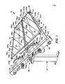
- Figs. 1 and 2 illustrate a solar reflector unit 10 having two solar reflectors 12a and 12b and a longitudinally-extending frame structure 14.
- the frame structure 14 has first and second generally parallel, longitudinally-extending, spaced-apart, lateral frame members 16 and 18 respectively.
- the lateral frame members 16 and 18 have respective first ends 20 and 22 and second ends 24 and 26.
- the frame structure 14 also has first 28 and second 30 generally parallel frame end closures 28 and 30.
- the first end closure 2P connects the first ends 20 and 22, and the second end closure 30 connects the second ends 24 and 26 of the lateral frame members 16 and 18.
- a first form member 32a, 32b is attached to extend generally parallel to and in-board of the first end closure 28.
- the first form member 32 is generally parallel to the first end closure 28 and generally perpendicular to the lateral frame members 16 and 18.
- a second form member 34a, 34b is parallel to the first form member 32a, 32b and in-board of the second end closure 30.
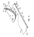
- the first 32a, 32b and second 34a, 34b form member 32a, 32b, 34a, 34b have peripheries 36a, 36b, 38a, 38b having identical form surfaces 40a, 40b, 42a, 42b (See Figs. 3, 4 and 5) along portions thereof.
- Trenches 43a,43b are located just outboard of the form surfaces 40a,40b,42a,42b for a purpose which will shortly become apparent.
- a support member 44a, 44b is attached to a respective one, 30 or 34a, 34b, of said second end closure 30 and said second end form member 34a, 34b.
- the support member 44a, 44b extends toward a respective other, 34a, 34b or 30, of the second end closure 30 and the second form member 34a, 34b.
- the support member 44a, 44b is adapted for transferring the weight of the second form member 34a, 34b to the second end closure 30.
- the support member 44a, 44b is preferably in the form of a bolt having a first end 46a, 46b attached to the respective second form member 34a, 34b, generally centrally thereof.
- the second end closure 30 preferably includes an opening 48a, 48b therethrough from a second form member facing side 50 to a second form member removed side 52.
- the support member 44a, 44b further has a second end 54a, 54b which extends through the opening 48a, 48b. Threads 55 on the first end 46a,46b of the support member 44a,44b provide means for stretching a flexible sheet 60 between the first 32a,32b and second 34a,34b form members 32a,32b,34a,34b so as to form the desired reflective configuration.
- biasing means 56b is provided for biasing the second form member 34a, 34b toward the second end closure 30 sufficiently to compensate for any differences in thermal expansion characteristics of the materials of construction of the solar reflectors 12a,12b.
- the biasing means 56 comprises a spring 57 which biases the second end 54a, 54b of the--support member 44a, 44b away from the second form member removed side 52 of the second end closure 30.
- a sleeve 58 is provided for spacing purposes. The sleeve 58 surrounds the support member 44a, 44b and is supported by, e.g., abuts, the second form member 34a, 34b.
- the sleeve 58 is selected to be of a length and contruction sufficient to limit how closely the support member 44a, 44b can approach the second form member 34a, 34b.
- the support member 44a, 44b is in the nature of a bolt which can be screwed into the second form member 34a, 34b.
- the sleeve 58 limits how far the bolt 44a, 44b can be screwed into the second form member 34a, 34b, thereby providing for a desired and controlled amount of biasing of the second form member 34a, 34b toward the second form member facing side 50 of the second end closure 30.
- a toggle arrangement can be used to compress the sprinq 57 a predetermined amount.
- the flexible sheet 60a,60b (see Figs. 4-7) has a reflective in-facing surface 62.
- the flexible sheet 60a,60b has opposite edges 64a, 64b, 66a, 66b which are adapted for attachment to the identical form surfaces 40a, 40b, 42a, 42b of the first 32a, 32b and second 34a, 34b form members 32a, 32b, 34a, 34b.
- the flexible sheet 60a,60b also has lateral edges 68a, 68b, 70a, 70b which are generally perpendicular to the first 32a, 3?b and second 34a, 34b form members 32a, 32b, 34a, and 34b.
- the flexible sheet can be made of plastic with an aluminized or other metal-coated surface, can be made of a sheet of metal such as aluminum, or can be made of any other material which has a reflective in-facing surface 62.
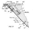
- securing means 72a, 72b, 74a, 74b are provided for securing the opposite edges 64a, 64b, 66a, 66b of the flexible sheet 60a, 60b to the identical form surfaces 40a, 40b, 42a, 42b.
- the securinq means 72a, 72h, 74a, 74b preferably includes first 76a, 76b and second 7Ra, 78b strap members 76a, 76b, 7Ra, 78b which are adapted for fitting in the trenches 43a,43b and means 80a, 80h in the embodiment illustrated pins 81, logitudinally extending slots 83, an opening 95 which matingly fits over an aligning pin 97, and bolts 85, for aligning the strap members 76a, 76b, 78a, 78b in fitting relation with the identical form surfaces 40a, 40b, 42a, 42b with the opposite edges 64a, 64b, 66a, 66b of the flexible sheet 60a, 60b sandwiched therebetween.
- Appropriate holes are provided in the opposite edges 64a, 64b, 66a, 66b of the flexible sheet 60a, 60b to accept the pins 81 and the aligning pin 97.
- the strap members 76a, 76b, 78a, 78b be bonded to the opposite edges 64a, 64b, 66a, 66b of the flexible sheet 60a, 60b.
- the sheet 60a, 60b is then stretched over the form surfaces 40a, 40b, 42a, 42b as the bolt 85 is tightened and the plug 87 is retracted.
- the securing means 72a, 72b, 74a, 74b further include means 82a, 82b, such as a plug 87 which may be moved longitudinally by tightening a bolt 89, for longitudinally tensioning the first 76a, 76b and second 78a, 78b strap members 76a, 76b, 78a, 78b for bearing inwardly against the opposite edges 64a, 64b, 66a, 66b of the flexible sheet 60a, 60b.
- the bolts 85 screw threadably engage in the plug 87 and move therewith to provide the needed tensioning.
- a slot 99 in the periphery 36a, 36b, 38a, 38b, allows appropriate movement of the bolt 85 with the plug 87.
- an arm 84a, 84b is provided having first 86a, 86b and second 88a, 88b longitudinally separated portions 86a, 86b, 88a, 88b.
- the first portion 86a, 86b (See Figure 8) is adjacent a respective one 16 or 18 of the lateral frame member 16, 18 or another relatively fixed support, and the second portion 88a, 88b is adjacent the second form member 34ab.
- Means 90a, 90b for example, a wedge 91ab and set screws 93ab, is provided for attaching the first portion 86a, 86b to the respective one 16 or 18 of the lateral frame member 16, 18.
- Means 92a, 92b is provided for attaching the second portion 88a, 88b to the second form member 34a, 34b.
- the arm 84a, 84b serves for positioning the second form member 34a, 34b to allow proper adjustment of the support member 44a, 44b.
- the arm 84a, 84b works in conjunction with the support member 44a, 44b to prevent rotation of the second form member 34a, 34b to allow easy installation of the flexible sheet 60a, 60b.
- the arm 84a, 84b it is necessary for someone to support the second form member 34a, 34b while the support member 44a, 44b is fastened in place and adjusted.
- the arm 84a, 84b serves a very important function.
- the arm 84a, 84b also serves to provide stiffening for the solar reflector 12a, 12b.
- Alternative structures to the arm 84a, 84b are also usable.
- a post may extend from a respective one of the second end closure 30 and the second member 34a, 34b and through a guide hole in a respective other thereof. The essential functioning provided is that of preventing rotation of the second member 34a, 34b relative to the second end closure 30. This is especially important during assembly but is also useful thereafter to provide increased structural integrity.
- first 94a, 94b and second 96a, 96b stiffening strips, 94a, 94b, 96a, 96b be attached to the lateral edges 68a, 68b, 70a, 70b of the flexible sheet 60 as by being bonded thereto by an appropriate adhesive.
- stiffening strips 94a, 94b, 96a, 96b are generally attached to the lateral edges 68a, 68b, 70a, 70b after the sheet 60a, 60b has been placed under tension
- the stiffening strips 94a, 94b, 96a, 96b provide not only stiffening for the flexible sheet 60a, 60b but also serve an additional purpose, as will shortly be pointed out.
- a transparent sheet 98a, 98b be provided having opposite sheet ends 100a, 100b, 101a, 101b adapted for alignment adjacent the opposite edges 64a, 64b, 66a, 66b of the flexible sheet 60a, 60b and lateral sheet ends 102a, 102b, 103a, 103b adapted for alignment adjacent the lateral edges 68a, 68b, 70a, 70b of the flexible sheet 60a, 60b.
- a cover frame 104a, 104b be provided, having opposite cover frame ends 106a, 106b, 108a, 108b attached to the opposite sheet ends 100a, 100b, 101a, 101b of the transparent sheet 98a, 98b and having lateral cover frame ends 110a, 110b, 112a, 112b attached to the lateral sheet ends 102a, 102b, 103a, 103b of the transparent sheet 98.
- the lateral cover frame ends 106a, 106b, 108a, 108b and the previously mentioned stiffening strips 94a, 94b, 96a, 96b define a snap engagement structure, 114a, 114b (Figs. 5 and 6) of the cover frame 104a, 104b-to the stiffening strips 94a, 94b,.96a, 96b.
- FIG. 1 Adverting to Fig. 1, it will be seen that the first end closure 28 and the second end closure 30 are pivotally mounted at 116, as at a pillow block, to a support structure 117.
- the particular embodiment of Figs. 1-8 shows a pair of solar reflectors 12a, 12b mounted to a single frame structure 14. As will be apparent, more than two solar reflectors 12a, 12b may be mounted to a single frame structure 14.
- a central linearly extending rod r20 connects the first end closure 28 with the second end closure 30 generally centrally to provide a balanced overall arrangement.
- Fig. 9 illustrates an embodiment of the present invention wherein eight different solar reflectors 12'a, 12'b, 12'c, 12'd, 12'e, 12'f, 12'g and 12'h form an overall solar collector unit 10 1 .
- Arms 84'a, and 84'd serve the same purpose as in the previous embodiment but are somewhat different in structure.
- Arms 184a, 184b, 184c serve a similar function to arms 84'a and 84'd except that the arms 184a, 184b, 184c attach one second form member 34'a, 34'b, 34'c, 34'd to a next adjacent second form member 34'a, 34'b, 34'c, 34'd.
- a single central pivotal adjustment at 116' provides tilting to properly focus the sun's rays on a plurality of target pipes 118'.
- a central frame member 121 serves for holding relatively stationary first form members 32'a, 32'b, 32'c, 132a, 132b, 132c, 132d.
- Corresponding second frame members 134a, 134b, 134c, 134d are mounted as are second frame members 34'a, 34'b, 34'c, 34'd.
- biasing means such as 56 of Fig. 1 are not shown for the embodiment of Fig. 9 it is contemplated that such may be useful.
- a solar reflector 12a, 12b is provided in accordance with the present invention which is useful for concentrating the sun's rays to heat fluids in pipes 118.
- the heated fluid can be used to generate energy, to heat a living or work space, or to heat anything needing heating.
Landscapes
- Engineering & Computer Science (AREA)
- Physics & Mathematics (AREA)
- Life Sciences & Earth Sciences (AREA)
- Sustainable Development (AREA)
- Sustainable Energy (AREA)
- Thermal Sciences (AREA)
- Chemical & Material Sciences (AREA)
- Combustion & Propulsion (AREA)
- Mechanical Engineering (AREA)
- General Engineering & Computer Science (AREA)
- Optical Elements Other Than Lenses (AREA)
- Photovoltaic Devices (AREA)
Applications Claiming Priority (2)
| Application Number | Priority Date | Filing Date | Title |
|---|---|---|---|
| US526632 | 1983-08-26 | ||
| US06/526,632 US4510923A (en) | 1983-08-26 | 1983-08-26 | Solar reflector |
Publications (2)
| Publication Number | Publication Date |
|---|---|
| EP0136044A2 true EP0136044A2 (de) | 1985-04-03 |
| EP0136044A3 EP0136044A3 (de) | 1986-04-23 |
Family
ID=24098114
Family Applications (1)
| Application Number | Title | Priority Date | Filing Date |
|---|---|---|---|
| EP84305637A Withdrawn EP0136044A3 (de) | 1983-08-26 | 1984-08-17 | Solarreflektor |
Country Status (9)
| Country | Link |
|---|---|
| US (1) | US4510923A (de) |
| EP (1) | EP0136044A3 (de) |
| JP (1) | JPS6090301A (de) |
| AU (1) | AU574093B2 (de) |
| IL (1) | IL72733A (de) |
| IN (1) | IN162584B (de) |
| MX (1) | MX161367A (de) |
| PH (1) | PH20952A (de) |
| ZA (1) | ZA846189B (de) |
Cited By (6)
| Publication number | Priority date | Publication date | Assignee | Title |
|---|---|---|---|---|
| DE20318080U1 (de) * | 2003-11-22 | 2005-04-14 | Restemeyer, Dieter | Vorrichtung zur Wärmegewinnung mittels Sonnenenergie |
| ITUD20090115A1 (it) * | 2009-06-09 | 2010-12-10 | Domenico Paolo Maria Cogliati | Struttura di supporto per impianti solari |
| WO2012052570A1 (es) * | 2010-10-18 | 2012-04-26 | Renovalia Energy, S.A. | Estructura de soporte de espejos o reflectores para sistemas de concentración solar y procedimiento de montaje de los espejos sobre la estructura |
| WO2013056279A1 (de) * | 2011-10-17 | 2013-04-25 | Kornmueller Manfred | Befestigungsanordnung für spiegelgläser geeignet für solaranlagen |
| EP2250526A4 (de) * | 2008-01-14 | 2013-08-21 | Focal Point Energy Inc | Sonnenkollektor mit gespannter membran und fassungsrand |
| CN105222089A (zh) * | 2014-06-26 | 2016-01-06 | 贺利氏特种光源美国有限责任公司 | 模块化uvled灯反射器组件 |
Families Citing this family (17)
| Publication number | Priority date | Publication date | Assignee | Title |
|---|---|---|---|---|
| US4596238A (en) * | 1983-08-26 | 1986-06-24 | Sunsteam Ltd. | Interiorly tensioned solar reflector |
| US4719903A (en) * | 1985-11-21 | 1988-01-19 | Powell Roger A | Variable aperture, variable flux density, aerospace solar collector |
| JPS63127054A (ja) * | 1986-11-14 | 1988-05-30 | Agency Of Ind Science & Technol | 集光集熱器 |
| US5071243A (en) * | 1990-03-19 | 1991-12-10 | Bronstein Allen I | Tensioned cover for parabolic reflector |
| US6273015B1 (en) * | 1998-02-26 | 2001-08-14 | Maruta Electric Boatworks Llc | Stabilized electric watercraft for high speed cruising, diving and sailing |
| US20080092878A1 (en) * | 2006-06-08 | 2008-04-24 | Kimura Darren T | Support of heat collectors in solar energy collectors |
| KR100807846B1 (ko) * | 2006-12-20 | 2008-02-27 | 성인식 | 태양열 보일러의 반원통형 집열장치 |
| WO2008124549A1 (en) * | 2007-04-04 | 2008-10-16 | Bronstein Allen I | Improved linear tensioned membrane reflector |
| US20100236600A1 (en) * | 2007-06-08 | 2010-09-23 | Sopogy, Inc. | Parking solar energy collectors |
| SE532465C2 (sv) * | 2007-10-22 | 2010-01-26 | Stefan Larsson | Solfångare |
| WO2009091756A2 (en) * | 2008-01-14 | 2009-07-23 | Focal Point Energy, Inc. | Improved stretched membrane solar collector |
| EP3193101A1 (de) | 2008-07-09 | 2017-07-19 | Skyfuel, Inc. | Sonnenkollektoren mit verschiebbar entfernbaren reflektierenden tafeln zur verwendung in solarthermischen anwendungen |
| US8739492B2 (en) | 2008-07-09 | 2014-06-03 | Skyfuel, Inc. | Space frame connector |
| WO2010022280A1 (en) * | 2008-08-22 | 2010-02-25 | Skyfuel, Inc. | Hydraulic-based rotational system for solar concentrators that resists high wind loads without a mechanical lock |
| CN101769636B (zh) * | 2008-12-29 | 2011-08-03 | 上海神曦太阳能科技有限公司 | 拼装式聚光太阳能采集装置及其拼装方法 |
| US20100199972A1 (en) * | 2009-01-14 | 2010-08-12 | Skyfuel, Inc. | Apparatus and Method for Building Linear Solar Collectors Directly from Rolls of Reflective Laminate Material |
| WO2015200306A1 (en) * | 2014-06-26 | 2015-12-30 | Heraeus Noblelight America Llc | Modular uv led lamp reflector assembly |
Family Cites Families (9)
| Publication number | Priority date | Publication date | Assignee | Title |
|---|---|---|---|---|
| US4000734A (en) * | 1975-11-06 | 1977-01-04 | Matlock William C | Solar energy converter |
| US4119365A (en) * | 1976-04-30 | 1978-10-10 | Roger Andrew Powell | Trough reflector |
| US4106484A (en) * | 1977-03-31 | 1978-08-15 | Mega Analytical Research Services, Inc. | Adjustable solar concentrator |
| US4205659A (en) * | 1977-08-08 | 1980-06-03 | Beam Engineering, Inc. | Solar energy collector |
| US4173397A (en) * | 1977-11-30 | 1979-11-06 | The United States Of America As Represented By The Administrator Of The National Aeronautics And Space Administration | Solar concentrator |
| US4220136A (en) * | 1978-09-13 | 1980-09-02 | Penney Richard J | Solar energy collector |
| US4243019A (en) * | 1978-10-25 | 1981-01-06 | Honeywell Inc. | Light-weight-trough type solar concentrator shell |
| US4358183A (en) * | 1980-05-09 | 1982-11-09 | Carl Whiteford | Solar reflecting panel |
| US4293192A (en) * | 1980-05-27 | 1981-10-06 | Bronstein Allen I | Solar reflector with flexible sheet tightly secured around form surfaces |
-
1983
- 1983-08-26 US US06/526,632 patent/US4510923A/en not_active Expired - Fee Related
-
1984
- 1984-08-09 ZA ZA846189A patent/ZA846189B/xx unknown
- 1984-08-14 AU AU31893/84A patent/AU574093B2/en not_active Ceased
- 1984-08-16 IN IN571/CAL/84A patent/IN162584B/en unknown
- 1984-08-17 EP EP84305637A patent/EP0136044A3/de not_active Withdrawn
- 1984-08-21 IL IL72733A patent/IL72733A/xx unknown
- 1984-08-22 PH PH31135A patent/PH20952A/en unknown
- 1984-08-24 MX MX202500A patent/MX161367A/es unknown
- 1984-08-25 JP JP59175873A patent/JPS6090301A/ja active Pending
Cited By (11)
| Publication number | Priority date | Publication date | Assignee | Title |
|---|---|---|---|---|
| DE20318080U1 (de) * | 2003-11-22 | 2005-04-14 | Restemeyer, Dieter | Vorrichtung zur Wärmegewinnung mittels Sonnenenergie |
| EP2250526A4 (de) * | 2008-01-14 | 2013-08-21 | Focal Point Energy Inc | Sonnenkollektor mit gespannter membran und fassungsrand |
| ITUD20090115A1 (it) * | 2009-06-09 | 2010-12-10 | Domenico Paolo Maria Cogliati | Struttura di supporto per impianti solari |
| WO2010143050A3 (en) * | 2009-06-09 | 2012-01-05 | Vetraria Biancadese Di Lucatello & C. Sas | Support structure for solar plants |
| CN102483267A (zh) * | 2009-06-09 | 2012-05-30 | 比昂卡迪斯·卢卡特罗玻璃制品有限公司 | 用于太阳能装置的支撑结构件 |
| CN102483267B (zh) * | 2009-06-09 | 2014-01-22 | 比昂卡迪斯·卢卡特罗玻璃制品有限公司 | 用于太阳能装置的支撑结构件 |
| US8863386B2 (en) | 2009-06-09 | 2014-10-21 | Vetraria Biancadese Di Lucatello & C. Sas | Support structure for solar plants and method for mounting |
| WO2012052570A1 (es) * | 2010-10-18 | 2012-04-26 | Renovalia Energy, S.A. | Estructura de soporte de espejos o reflectores para sistemas de concentración solar y procedimiento de montaje de los espejos sobre la estructura |
| WO2013056279A1 (de) * | 2011-10-17 | 2013-04-25 | Kornmueller Manfred | Befestigungsanordnung für spiegelgläser geeignet für solaranlagen |
| CN105222089A (zh) * | 2014-06-26 | 2016-01-06 | 贺利氏特种光源美国有限责任公司 | 模块化uvled灯反射器组件 |
| CN105222089B (zh) * | 2014-06-26 | 2019-10-11 | 贺利氏特种光源美国有限责任公司 | 模块化uvled灯反射器组件 |
Also Published As
| Publication number | Publication date |
|---|---|
| MX161367A (es) | 1990-09-18 |
| IL72733A (en) | 1988-08-31 |
| EP0136044A3 (de) | 1986-04-23 |
| AU3189384A (en) | 1985-02-28 |
| ZA846189B (en) | 1985-03-27 |
| IL72733A0 (en) | 1984-11-30 |
| PH20952A (en) | 1987-06-10 |
| IN162584B (de) | 1988-06-11 |
| JPS6090301A (ja) | 1985-05-21 |
| US4510923A (en) | 1985-04-16 |
| AU574093B2 (en) | 1988-06-30 |
Similar Documents
| Publication | Publication Date | Title |
|---|---|---|
| EP0136044A2 (de) | Solarreflektor | |
| US4293192A (en) | Solar reflector with flexible sheet tightly secured around form surfaces | |
| US4493313A (en) | Parabolic trough solar collector | |
| US4611575A (en) | Parabolic trough solar reflector | |
| US4071017A (en) | Tensioned reflector support system | |
| US4597377A (en) | Solar reflector system | |
| US5058565A (en) | Solar concentrator device and support structure therefor | |
| US4596238A (en) | Interiorly tensioned solar reflector | |
| US4820033A (en) | Solar mirror apparatus | |
| US5964216A (en) | Trough-type parabolic concentrator | |
| US4161942A (en) | Solar energy collector | |
| US5104211A (en) | Splined radial panel solar concentrator | |
| US7875796B2 (en) | Reflector assemblies, systems, and methods for collecting solar radiation for photovoltaic electricity generation | |
| US4422614A (en) | Support means for a plurality of solar panels | |
| MA24762A1 (fr) | Mecanisme de chauffage a l'aide d'energie solaire | |
| AU8513598A (en) | Nontracking solar concentrators | |
| CN1286804A (zh) | 用于航天器的收放式薄膜型太阳能聚集器 | |
| AU600925B2 (en) | Concave mirror apparatus and method of construction | |
| US4251135A (en) | Solar reflector | |
| ES8104535A1 (es) | Perfeccionamientos en colectores solares planos por concen- tracion | |
| US4102329A (en) | System for collecting solar energy | |
| WO1991012402A1 (en) | A hinge connection | |
| CA2589080C (en) | A reflector assembly for energy concentrators | |
| FR2704629B1 (fr) | Film chauffant a structure modulaire, pour chauffage par rayonnement, et dispositif pour sa connexion. | |
| FR2711219B1 (fr) | Luminaire à réflecteur latéral orientable. |
Legal Events
| Date | Code | Title | Description |
|---|---|---|---|
| PUAI | Public reference made under article 153(3) epc to a published international application that has entered the european phase |
Free format text: ORIGINAL CODE: 0009012 |
|
| AK | Designated contracting states |
Designated state(s): DE FR GB IT |
|
| PUAL | Search report despatched |
Free format text: ORIGINAL CODE: 0009013 |
|
| AK | Designated contracting states |
Kind code of ref document: A3 Designated state(s): DE FR GB IT |
|
| 17P | Request for examination filed |
Effective date: 19861021 |
|
| 17Q | First examination report despatched |
Effective date: 19870407 |
|
| STAA | Information on the status of an ep patent application or granted ep patent |
Free format text: STATUS: THE APPLICATION IS DEEMED TO BE WITHDRAWN |
|
| 18D | Application deemed to be withdrawn |
Effective date: 19910813 |
|
| APAF | Appeal reference modified |
Free format text: ORIGINAL CODE: EPIDOSCREFNE |