EP0135816B1 - Sende- und Empfangssystem für Signale - Google Patents
Sende- und Empfangssystem für Signale Download PDFInfo
- Publication number
- EP0135816B1 EP0135816B1 EP84110086A EP84110086A EP0135816B1 EP 0135816 B1 EP0135816 B1 EP 0135816B1 EP 84110086 A EP84110086 A EP 84110086A EP 84110086 A EP84110086 A EP 84110086A EP 0135816 B1 EP0135816 B1 EP 0135816B1
- Authority
- EP
- European Patent Office
- Prior art keywords
- signal
- oscillator
- receiver
- transmission
- output
- Prior art date
- Legal status (The legal status is an assumption and is not a legal conclusion. Google has not performed a legal analysis and makes no representation as to the accuracy of the status listed.)
- Expired
Links
Images
Classifications
-
- H—ELECTRICITY
- H04—ELECTRIC COMMUNICATION TECHNIQUE
- H04B—TRANSMISSION
- H04B1/00—Details of transmission systems, not covered by a single one of groups H04B3/00 - H04B13/00; Details of transmission systems not characterised by the medium used for transmission
- H04B1/38—Transceivers, i.e. devices in which transmitter and receiver form a structural unit and in which at least one part is used for functions of transmitting and receiving
- H04B1/40—Circuits
- H04B1/50—Circuits using different frequencies for the two directions of communication
-
- H—ELECTRICITY
- H04—ELECTRIC COMMUNICATION TECHNIQUE
- H04B—TRANSMISSION
- H04B1/00—Details of transmission systems, not covered by a single one of groups H04B3/00 - H04B13/00; Details of transmission systems not characterised by the medium used for transmission
- H04B1/38—Transceivers, i.e. devices in which transmitter and receiver form a structural unit and in which at least one part is used for functions of transmitting and receiving
- H04B1/40—Circuits
- H04B1/403—Circuits using the same oscillator for generating both the transmitter frequency and the receiver local oscillator frequency
- H04B1/408—Circuits using the same oscillator for generating both the transmitter frequency and the receiver local oscillator frequency the transmitter oscillator frequency being identical to the receiver local oscillator frequency
Definitions
- the present invention relates to the field of signal transmission and reception systems using a receiver which employs the superheterodyne system, and in particular, to systems which are adapted to share the radio frequency portion by using the transmission oscillator of the transmitter as the local oscillator of the receiver.
- Conventional communication systems, typically radio or wireless telephones, of the duplex transmission system having a receiver of the superheterodyne system are designed such that the output of the transmission oscillator (channel oscillator) is modulated by an aural signal, etc., the oscillator output thus modulated is transmitted from an antenna at a transmission frequency fT through an amplifier and an antenna duplexer, a receiving signal of the frequency fR fed to a receiver through the antenna and the antenna duplexer is mixed at a mixer, with a signal fT generated by a local oscillator of the receiver, and an intermediate frequency fl which is lower than the frequency fR of the receiving signal is extracted through an intermediate frequency filter and picked up as an aural signal by a frequency discriminator.
- the transmission oscillator channel oscillator
- the system is usually designed so as to satisfy In such design, since the oscillation frequency of the local oscillator is the same fT with that of the transmission oscillator, a single oscillator may be shared for both the local and the transmission oscillators, whereby cost is reduced.
- the above method involves a problem that when a single oscillator is used for the above two oscillators, the transmission signal modulated by the aural signal, etc. is directly demodulated by the receiver so that it can be unfavorably heard as a side tone.
- DE-B-10 02 805 describes a duplex transmission system of the type as mentioned in the precharacterizing part of the Claim.
- the known signal transmission and reception system has an oscillator used in common for the local oscillator of the receiver, and the oscillator of the transmitter and the modulated output of the transmission oscillator are used as the local oscillator output of the receiver.
- the receiver is the double superheterodyne system and the aforementioned modulation signal which has provided required phase shift is fed to a second local oscillator of said superheterodyne system.
- the modulation signal component contained in a second mixer output is cancelled at the intermediate frequency conversion stage.
- the compensation of the modulator signal is effected in the second mixing stage of the receiver, therefore, an additional oscillator is required for delivering a level adjusted and phase inverted modulated signal to the second mixing stage.
- the modulation signal component which is suppressed in the receiver cannot be removed sufficiently.
- Similar systems are described in FR-A-1 362 913 and GB-A-2 005 113. Said systems need two oscillators, one of which is the transmission oscillator and the other one is an auxiliary oscillator which is modulated by the level adjusted and phase inverted compensation signal. The output of the auxiliary oscillator ip mixed in the receiver for compensating the modulation signal component contained in the receiver.
- the system of the present invention comprises modulation means for modulating the output of the transmission oscillator by the modulation signal level adjusted to a required value and a phase invented to cancel the modulation signal component, wherein the local oscillator of the receiver is dispensed with by supplying the output of the above modulation means to the mixer as the local oscillator output of the superheterodyne receiver.
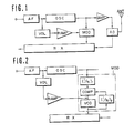
- the output of a transmission oscillator (channel oscillator) OSC modulated by an output signal of an aural signal circuit AF is transmitted from an antenna ANT through an amplifer AMP and an antenna duplexer AD.
- the output of the transmission oscillator OSC is fed to the receiver. That is, the transmission oscillator OSC is used as a first local oscillator L01 of the receiver RX.
- the modulator signal is adjusted at a level adjusting circuit VOL and a phase inverter R ⁇ AMP so that its level and phase become the same modulation factor as the modulated signal component of the output of the transmission oscillator OSC.
- the modulated output signal namely the output of the transmission oscillator OSC, is fed to a modulator MOD.
- the level of the modulator signal is adjusted at a level adjusting circuit VOL, the modulation factor of the modulator MOD is made equal to the modulation factor of the modulated signal of the oscillator OSC output, the phase is inverted through a reverse amplifier R ⁇ AMP, and the output thereof is fed to the modulator MOD.
- the carrier namely the output thereof, is fed to the first mixer of the receiver RX.
- phase shifter having the equivalent function may be used in lieu of the reverse amplifier R - AMP.
- the reverse amptifier R ⁇ AMP is configured as shown in Figure 5.
- the output of the oscillator OSC made to a suitable frequency at a first divider (1/N) is fed to a phase comparator COMP as a reference signal of the closed loop phase lock system comprised of a voltage controlled oscillator VCO, a second divider (1/N)2, and the phase comparator COMP, the modulation signal component contained in the output of the first divider (1/N)1 is cancelled by the modulation signal having been level-adjusted at a level adjusting circuit VOL and phase-inverted at a reversing amplifier R - AMP, and a carrier having been rid of the modulation signal component is obtained by the output of the voltage controlled oscillator VCO.
- the modulator MOD when the modulator of the channel oscillator OSC is of the frequency modulation system and the modulation signal circuit AF comprises a pre-emphasis circuit, since the modulated signal, namely the output of the channel oscillator OSC, is phase-modulated,the modulator MOD must be a frequency modulator.
- the modulator of the oscillator OSC when the modulator of the oscillator OSC is of the phase modulation system, the modulator MOD should also be a phase modulator, since the modulation signal circuit AF has no pre-emphasis circuit, however, it is apparent that the modulator MOD should be a frequency modulator having a pre-emphasis circuit.
Landscapes
- Engineering & Computer Science (AREA)
- Computer Networks & Wireless Communication (AREA)
- Signal Processing (AREA)
- Transceivers (AREA)
Claims (1)
- Signalsende- und Empfangssystem mit:einem Empfänger (Rx) von Superhet-Typ,einem Sender mit einem Sendeoszillator (OSC), der durch ein Modulationssignal moduliert wird, wobei der Sendeoszillator (OSC) zusätzlich zur Erzeugung eines Frequenzsignals verwendet wird, das in dem Empfänger (Rx) mit einem Empfangssignal gemischt wird,und einer Einrichtung (VOL, R - AMP, MOD) zum Kompensieren der durch das Modulationssignal verursachten Modulationssignalkomponente, zur Unterdrückung der Modulationssignalkomponente in dem Ausgangssignal des Empfängers (Rx), wobei die Kompensiereinrichtung Einstellmittel (VOL, R - AMP) zur Pegeleinstellung und Phaseninversion des Modulationssignals aufweist, dadurch gekennzeichnet, daßdie Kompensiereinrichtung (VOL, R · AMP, MOD) einen Modulator (MOD) aufweist, der das modulierte Ausgangssignal des Sendeoszillators (OSC) mit dem Ausgangssignal der Einstellmittel (VOL, R - AMP) so moduliert, daß der Modutator (MOD) dem Empfänger (Rx) eine im wesentlichen unmodulierte Frequenz zuführt, die der Oszillierfrequenz des Sendeoszillators (OSC) entspricht.
Applications Claiming Priority (4)
| Application Number | Priority Date | Filing Date | Title |
|---|---|---|---|
| JP155327/83 | 1983-08-24 | ||
| JP58155327A JPS6046622A (ja) | 1983-08-24 | 1983-08-24 | 受信機の局部発振器を送信機のチャンネル発振器と共用した同時送受話通信装置 |
| JP15848584A JPS6139630A (ja) | 1984-07-28 | 1984-07-28 | 受信機局部発振器と送信機チヤンネル発振器とを共用した同時送受話通信方式 |
| JP158485/84 | 1984-07-28 |
Publications (3)
| Publication Number | Publication Date |
|---|---|
| EP0135816A2 EP0135816A2 (de) | 1985-04-03 |
| EP0135816A3 EP0135816A3 (en) | 1986-02-05 |
| EP0135816B1 true EP0135816B1 (de) | 1989-05-24 |
Family
ID=26483356
Family Applications (1)
| Application Number | Title | Priority Date | Filing Date |
|---|---|---|---|
| EP84110086A Expired EP0135816B1 (de) | 1983-08-24 | 1984-08-23 | Sende- und Empfangssystem für Signale |
Country Status (4)
| Country | Link |
|---|---|
| US (1) | US4633511A (de) |
| EP (1) | EP0135816B1 (de) |
| CA (1) | CA1231384A (de) |
| DE (1) | DE3478376D1 (de) |
Families Citing this family (11)
| Publication number | Priority date | Publication date | Assignee | Title |
|---|---|---|---|---|
| US4969210A (en) * | 1988-02-10 | 1990-11-06 | Motorola, Inc. | Two-way radio having a PLL |
| GB8806194D0 (en) * | 1988-03-16 | 1988-04-13 | Shaye Communications Ltd | Transceivers |
| FI80550C (fi) * | 1989-01-13 | 1990-06-11 | Telenokia Oy | Frekvensmodulerad saendarmottagare. |
| FI80549C (fi) * | 1989-01-13 | 1990-06-11 | Telenokia Oy | Frekvensmodulerad saendarmottagare. |
| DE4021294A1 (de) * | 1990-07-04 | 1992-01-09 | Grundig Emv | Sende- und n-fach-superhet-empfangseinrichtung fuer ein geraet der nachrichtentechnik |
| EP0488476A3 (en) * | 1990-11-29 | 1992-12-16 | N.V. Philips' Gloeilampenfabrieken | Radio transceiver |
| FI94808C (fi) * | 1991-08-29 | 1995-10-25 | Nokia Telecommunications Oy | Taajuusmoduloitu lähetinvastaanotin |
| US5444864A (en) * | 1992-12-22 | 1995-08-22 | E-Systems, Inc. | Method and apparatus for cancelling in-band energy leakage from transmitter to receiver |
| US5710998A (en) * | 1995-12-19 | 1998-01-20 | Motorola, Inc. | Method and apparatus for improved zero intermediate frequency receiver latency |
| US6219531B1 (en) * | 1998-09-04 | 2001-04-17 | Ericsson Inc. | Architecture and frequency plan for a UHF portable radio |
| US8385476B2 (en) | 2001-04-25 | 2013-02-26 | Texas Instruments Incorporated | Digital phase locked loop |
Family Cites Families (8)
| Publication number | Priority date | Publication date | Assignee | Title |
|---|---|---|---|---|
| DE1002805B (de) * | 1955-02-02 | 1957-02-21 | Telefunken Gmbh | Als Funkrelaisstelle einsetzbares oder mit einer Drahtfernsprechleitung in Verbindung zu bringendes Funksprechgeraet |
| GB834636A (en) * | 1958-05-29 | 1960-05-11 | Standard Telephones Cables Ltd | Method for the frequency synthesis in duplex radio sets |
| GB923178A (en) * | 1960-12-22 | 1963-04-10 | Gen Electric Co Ltd | Improvements in or relating to radio apparatus for use in a continuous wave radio system |
| CH394316A (de) * | 1962-07-13 | 1965-06-30 | Patelhold Patentverwertung | Sende- und Empfangsanordnung für drahtlose Nachrichtenübertragung |
| US3254338A (en) * | 1964-01-28 | 1966-05-31 | Westinghouse Electric Corp | Continuous wave doppler radar system |
| JPS5380906A (en) * | 1976-12-27 | 1978-07-17 | Oki Electric Ind Co Ltd | Frequency converter |
| DE2744212C2 (de) * | 1977-09-30 | 1979-11-08 | Siemens Ag, 1000 Berlin Und 8000 Muenchen | Duplex-Sende-Empfangseinrichtung |
| US4520747A (en) * | 1984-02-27 | 1985-06-04 | Masters William E | Breakaway kayak cockpit and method |
-
1984
- 1984-08-23 US US06/643,834 patent/US4633511A/en not_active Expired - Fee Related
- 1984-08-23 EP EP84110086A patent/EP0135816B1/de not_active Expired
- 1984-08-23 DE DE8484110086T patent/DE3478376D1/de not_active Expired
- 1984-08-24 CA CA000461781A patent/CA1231384A/en not_active Expired
Also Published As
| Publication number | Publication date |
|---|---|
| US4633511A (en) | 1986-12-30 |
| CA1231384A (en) | 1988-01-12 |
| EP0135816A3 (en) | 1986-02-05 |
| DE3478376D1 (en) | 1989-06-29 |
| EP0135816A2 (de) | 1985-04-03 |
Similar Documents
| Publication | Publication Date | Title |
|---|---|---|
| US5444865A (en) | Generating transmit injection from receiver first and second injections | |
| US4520474A (en) | Duplex communication transceiver with modulation cancellation | |
| US5483679A (en) | Radio communication apparatus capable of isolating a receiver from a transmitter during a reception operation | |
| WO1995021493A1 (en) | Local oscillator phase noise cancelling modulation technique | |
| EP0135816B1 (de) | Sende- und Empfangssystem für Signale | |
| EP0046682B1 (de) | Einkanaliges Duplex-Nachrichtensystem | |
| WO1994026049A2 (en) | Wireless data transceiver | |
| US6922402B1 (en) | Mutual frequency locking across a link | |
| US4349919A (en) | Transmitter/receivers capable of contemporaneous transmission/reception | |
| US4509200A (en) | Satellite telecommunications system | |
| EP0529767B1 (de) | Digitales Funkgerät | |
| AU748309B2 (en) | Radio transmitter/receiver | |
| US4450583A (en) | Multi-channel transceiver using a single high-stability element | |
| US4520475A (en) | Duplex communication transceiver with modulation cancellation | |
| JPS61105127A (ja) | マイクロ波二重通信装置 | |
| JPS6046622A (ja) | 受信機の局部発振器を送信機のチャンネル発振器と共用した同時送受話通信装置 | |
| EP0165265A1 (de) | Duplexfähiger verbindungssender/-empfänger mit modulationsunterdrückung | |
| FI94808B (fi) | Taajuusmoduloitu lähetinvastaanotin | |
| EP0471952A3 (en) | Transmitter- and multiple conversion superhet receiver for a telecommunication device | |
| KR970002956B1 (ko) | 다채널 송수신용 모뎀 | |
| US6137997A (en) | Circuit for receiving and transmitting signals and method | |
| JPS5830242A (ja) | 移動無線通信方式 | |
| JPH04245814A (ja) | Fm送信回路 | |
| CA2056903A1 (en) | Radio transceiver | |
| JPH06164491A (ja) | ディジタル携帯電話 |
Legal Events
| Date | Code | Title | Description |
|---|---|---|---|
| PUAI | Public reference made under article 153(3) epc to a published international application that has entered the european phase |
Free format text: ORIGINAL CODE: 0009012 |
|
| AK | Designated contracting states |
Designated state(s): DE GB SE |
|
| PUAL | Search report despatched |
Free format text: ORIGINAL CODE: 0009013 |
|
| AK | Designated contracting states |
Designated state(s): DE GB SE |
|
| 17P | Request for examination filed |
Effective date: 19860804 |
|
| 17Q | First examination report despatched |
Effective date: 19871113 |
|
| GRAA | (expected) grant |
Free format text: ORIGINAL CODE: 0009210 |
|
| AK | Designated contracting states |
Kind code of ref document: B1 Designated state(s): DE GB SE |
|
| REF | Corresponds to: |
Ref document number: 3478376 Country of ref document: DE Date of ref document: 19890629 |
|
| PLBE | No opposition filed within time limit |
Free format text: ORIGINAL CODE: 0009261 |
|
| STAA | Information on the status of an ep patent application or granted ep patent |
Free format text: STATUS: NO OPPOSITION FILED WITHIN TIME LIMIT |
|
| 26N | No opposition filed | ||
| EAL | Se: european patent in force in sweden |
Ref document number: 84110086.0 |
|
| PGFP | Annual fee paid to national office [announced via postgrant information from national office to epo] |
Ref country code: DE Payment date: 19960919 Year of fee payment: 13 |
|
| PGFP | Annual fee paid to national office [announced via postgrant information from national office to epo] |
Ref country code: GB Payment date: 19970806 Year of fee payment: 14 |
|
| PGFP | Annual fee paid to national office [announced via postgrant information from national office to epo] |
Ref country code: SE Payment date: 19970822 Year of fee payment: 14 |
|
| PG25 | Lapsed in a contracting state [announced via postgrant information from national office to epo] |
Ref country code: DE Free format text: LAPSE BECAUSE OF NON-PAYMENT OF DUE FEES Effective date: 19980501 |
|
| PG25 | Lapsed in a contracting state [announced via postgrant information from national office to epo] |
Ref country code: GB Free format text: LAPSE BECAUSE OF NON-PAYMENT OF DUE FEES Effective date: 19980823 |
|
| PG25 | Lapsed in a contracting state [announced via postgrant information from national office to epo] |
Ref country code: SE Free format text: LAPSE BECAUSE OF NON-PAYMENT OF DUE FEES Effective date: 19980824 |
|
| GBPC | Gb: european patent ceased through non-payment of renewal fee |
Effective date: 19980823 |
|
| EUG | Se: european patent has lapsed |
Ref document number: 84110086.0 |