EP0135170A2 - Gerät zur Beobachtung von Blutströmungsmustern - Google Patents
Gerät zur Beobachtung von Blutströmungsmustern Download PDFInfo
- Publication number
- EP0135170A2 EP0135170A2 EP84109956A EP84109956A EP0135170A2 EP 0135170 A2 EP0135170 A2 EP 0135170A2 EP 84109956 A EP84109956 A EP 84109956A EP 84109956 A EP84109956 A EP 84109956A EP 0135170 A2 EP0135170 A2 EP 0135170A2
- Authority
- EP
- European Patent Office
- Prior art keywords
- signals
- pulsed doppler
- digital
- signal
- blood flow
- Prior art date
- Legal status (The legal status is an assumption and is not a legal conclusion. Google has not performed a legal analysis and makes no representation as to the accuracy of the status listed.)
- Granted
Links
Images


Classifications
-
- A—HUMAN NECESSITIES
- A61—MEDICAL OR VETERINARY SCIENCE; HYGIENE
- A61B—DIAGNOSIS; SURGERY; IDENTIFICATION
- A61B8/00—Diagnosis using ultrasonic, sonic or infrasonic waves
-
- G—PHYSICS
- G01—MEASURING; TESTING
- G01S—RADIO DIRECTION-FINDING; RADIO NAVIGATION; DETERMINING DISTANCE OR VELOCITY BY USE OF RADIO WAVES; LOCATING OR PRESENCE-DETECTING BY USE OF THE REFLECTION OR RERADIATION OF RADIO WAVES; ANALOGOUS ARRANGEMENTS USING OTHER WAVES
- G01S15/00—Systems using the reflection or reradiation of acoustic waves, e.g. sonar systems
- G01S15/88—Sonar systems specially adapted for specific applications
- G01S15/89—Sonar systems specially adapted for specific applications for mapping or imaging
- G01S15/8906—Short-range imaging systems; Acoustic microscope systems using pulse-echo techniques
- G01S15/8979—Combined Doppler and pulse-echo imaging systems
-
- A—HUMAN NECESSITIES
- A61—MEDICAL OR VETERINARY SCIENCE; HYGIENE
- A61B—DIAGNOSIS; SURGERY; IDENTIFICATION
- A61B8/00—Diagnosis using ultrasonic, sonic or infrasonic waves
- A61B8/06—Measuring blood flow
Definitions
- the present invention relates to an apparatus for observing blood flow patterns by way of ultrasonic beams, where the ultrasonic beams are transmitted to an object such as a biomedical body, and then ultrasonic echoes reflected from the object are processed by phase detectors, whereby the blood flow patterns, e.g., the blood flow patterns in a heart, can be visualized without giving invasive effects to the object.
- physiological saline is injected into a vein of an object to be examined and is circulated together with a blood flow in the heart, thereby displaying a blood flow in a tomographic image. This method is called "a contrast echo method" and is used in practice.
- the contrast echo method involves an intravenous injection in the object (an invasive method).
- an invasive method According to this method, only a blood flow image of the right atrium and ventricle (which pump out a blood flow to the lungs) is displayed.
- the blood flow of the left atrium and ventricle cannot be displayed although this flow must be clarified as a first priority for diagnostic purposes, resulting in inconvenience.
- this method does not display the blood flow itself but displays the distribution map of blood flow, which does not give direct information about the direction of the blood flow. In other words, a flow speed is calculated and is displayed. Only the blood flow component (coming toward or going away from the emitting direction of the ultrasonic beam) parallel to the emission direction thereof is given. For this reason, even if the blood flow is oblique along the direction of the ultrasonic beam, information about an actual direction of the blood flow cannot be obtained.
- the present invention has been made in consideration of those conventional inherent problems, and has as its object to provide an apparatus for observing blood flow patterns, wherein a blood current direction can be displayed by detecting blood flows parallel to an ultrasonic beam and perpendicular thereto in a noninvasive manner.
- the object of the present invention may be accomplished by providing an apparatus for observing blood flow patterns by way of ultrasonic beams, comprising,
- Ultrasonic echoes reflected by respective portions (organs and bones) of an object under examination are obtained such that a strong reflection signal from a muscle or the like is superposed on a weak reflection signal which has a signal strength of about 1/100 that of the strong reflection signal and which is reflected from blood cells or hemocytes.
- the strong reflection signal i.e., clutter reflection signal
- the weak reflection signal from the blood cells or hemocytes can be obtained. Since the blood cells or hemocytes move together with a blood flow, the weak reflection signal is obtained as a Doppler shift signal corresponding to a blood flow speed.
- the phase of the Doppler shift signal varies in accordance with a distance from an emission point of the ultrasonic beam to a reflection point thereof.
- the phase is shifted at the same speed as the blood flow speed. Therefore, the blood flow speed can be detected in accordance with phase information.
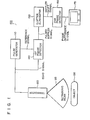
- a pulse generator 110 is arranged to generate exciting pulse signals so as to excite a transducer 120.
- this exciting pulse signal serves as a reference signal of a first phase detector 140.
- the transducer 120 is excited in response to this exciting pulse signal and generates ultrasonic beams 125.
- An object 130 such as a patient is scanned with these ultrasonic beams 125 in, for example, a "sector" form.
- Reflected ultrasonic beams, i.e., ultrasonic echoes are obtained from the respective internal portions, e.g., blood cells of the object 130 and are received by the transducer 120. Thereafter, the ultrasonic echoes are converted to an echo pulse signal (to be referred to as an echo signal for brevity hereafter).
- the echo signal is phase-detected by the first phase detector 140 in accordance with the reference signal (exciting pulse signal), thereby obtaining one-dimensional amplitude information, i.e., a pulsed Doppler signal.
- a clutter signal component is eliminated by a clutter eliminator 150 from the pulse Doppler signal of the first phase detector 140 to obtain a phase-detected echo signal component from blood cells.
- a Doppler shift signal is obtained.
- This Doppler shift signal is phase-processed by a second phase detector 160.
- the echo signals are sequentially obtained from the respective internal portions of the object 130 at given time intervals. Echo signals from two given internal portions are sampled over time, and phase differences between every two echo signals of these two given portions sampled at identical moments are calculated to obtain a phase difference signal.
- the phase difference signals are brightness-modulated, and the resultant phase difference signals are displayed on, for example, a TV monitor 170.
- the blood flow conditions such as the blood flow direction can be displayed.
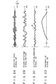
- the abscissa (time) "t” in Fig. 2A corresponds to the distance "x".
- FIG. 2B shows a signal (a "phase-detected signal ec + ed") obtained by phase-detecting the received echo signal erf, as a superposed signal of a signal ec from the clutter and a weak signal ed from the blood flow.
- Fig. 2C shows the signal ed obtained by eliminating the clutter signal ec from the phase-detected signal (ec + ed).
- the amplitude of the clutter-eliminated signal ed is very small. However, this amplitude is illustrated in an amplified manner in Fig. 2C.
- Fig. 2D shows a signal component indicated by "D" in the signal ed of Fig. 2C which is enlarged with respect to the abscissa.
- Fig. 3 . is an illustrative representation of the principle of the present invention.
- sample volume The center of a predetermined spatial sample volume ⁇ x (simply referred to as "sample volume") within the blood flow is plotted along the x-axis.
- a phase of a reflection signal from a blood flow within a sample volume adjacent to the sample volume Ax is different from that within the sample volume Ax.
- the phases of the reflection signals vary in accordance with changes in positions x.
- the blood flow speeds, i.e., "fd" at these sample volumes are substantially the same, and the coefficients A(x) for determining the amplitudes of the reflection signals are substantially the same as follows:
- phase difference A 3 (x) between the reflection signals at the two adjacent sample volumes must be calculated.
- the principle of the present invention can be illustratively understood from Fig. 3.
- the waveform of the phase-detected signal (pulsed Doppler signal) from the first phase detector 140 of Fig. 1 is illustated as the signal ed along the x-axis of Fig. 3 (a travel path of the ultrasonic beams).
- This phase-detected signal can be obtained for every one rate pulse.
- the n signals ed are obtained along the T -axis (the time lapse).
- T the time lapse
- One rate pulse has a pulse width of ⁇ , so that the signals ed are plotted parallel to each other along the T -axis.
- the clutter signal components are eliminated from the pulsed Doppler signals, and pulsed Doppler shift signals at the respective points along the x-axis are sampled by range gating means.
- the phase differences between every two adjacent sampled Doppler shift signals are calculated by the second phase detector 160 that is the main feature.
- the second phase detector 160 For illustrative convenience, only two sampled Doppler shift signals for calculating a phase difference therebetween have been selected, and their amplitude changes ed(xO-VxT,T) and ed(xl-VxT,T) are illustrated.
- the present invention has been made on the basis of the following.
- the blood flow speed and a directional sign indicating that the blood flow is flowing toward or away from the transducer can be detected.
- the direction of the blood flow at each internal portion of the object cannot be displayed as well as flow conditions.
- amplitude information at predetermined sampling points e.g., xl and x0
- the sampling periods are determined in accordance with a depth of the object along a travel path of the ultrasonic beams.
- the phase differences between every two adjacent sampled Doppler signals are obtained in accordance with these pieces of information.
- phase relationship between the phase differences is maintained within a predetermined short time period. It should be noted that it is also possible to obtain the phase differences between two Doppler signals which have been arbitrary sampled from the Doppler shift signal ed. The phase differences are acquired during the respective signal amplitudes of the corresponding sampling points. When the acquired phase differences are displayed, the blood flow direction is visuable.
- calculation and display of the phase differences can be performed in a real-time manner since an operation such as a Fourier transform need not be performed.
- the pulse generator 110 comprises a clock pulse generator 12 for generating the reference clock pulse, a rate pulse generator 16 for frequency-dividing the reference clock pulse from the clock pulse generator 12 and generating a rate pulse, and a reference signal generator 18 for frequency-dividing the reference clock pulse and generating a reference signal to the first phase detector 140.
- the first phase detector 140 for detecting a phase of an ultrasonic echo signal transduced by the transducer 120 has a mixer 20, a low-pass filter (LPF) 22 and an amplifier 24.
- the reflection signal from the amplifier 24 is multiplied with the reference signal having substantially the same center frequency as in the reflection signal and is generated from the reference signal generator 18, and a high-frequency component is cut off from the resultant product signal, thereby detecting the phase of the reflection signal.
- the clutter eliminator 150 for eliminating the clutter signal component from the output signal from the first phase detector 140 comprises an A/D converter 32 for converting to a digital signal the reflection signal generated from the low-pass filter 22, and a digital comb filter 34 for eliminating the cluttered signal ec from the reflection signal.
- the digital comb filter 34 may include adders 310 and 320, a shift register 330 and a multiplier 340, as shown in Fig. 5A.
- the digital comb fiter 34 has band-pass filter characteristics, as shown in Fig. 5B.
- the digital comb filter 34 includes a higher-order filter having a plurality of stages, better filter characteristics can be obtained.
- the digital comb filter 34 includes a single stage digital filter of the second order which consists of adders 311 and 321, shift registers 330A and 330B, and multipliers 340A, 340B, 340C, 340D and 340E.
- the desired filtering effect can be obtained.
- the output from the digital comb filter 34 is free from the cluttered signal ec and corresponds to the reflection signal ed whose waveform is illustrated in Figs. 2C and 2D.
- the second phase detector 160 connected to the output of the clutter eliminator 150 has a delay circuit 42 for delaying the reflection signal ed from the blood cells by the delay time (approx. 2Ax/c) corresponding to the pulse width, a multiplier 44 for multiplying the reflection signal ed from the blood cells with a delayed reflection signal edd from the delay circuit 42, and an adder 46 for simply adding the signals of several rates from the multiplier 44 n times.
- an AC component of the sum signal from the adder 46 is removed to generate a signal corresponding to E(x, ⁇ ) in equation ( 8 ).
- the clutter eliminator 150 and the second phase detector 160 connected to the output of the clutter eliminator 150 are designed in a digital circuit, so that the signal delay can be more accurate and simpler than that of an analogue circuit.
- the display unit having the TV monitor 170 is arranged such that the signal corresponding to E(X,T) is converted by a D/A converter 52 to an analogue signal, and the resultant analogue signal is luminance-modulated by the TV monitor 170 and is displayed on a screen via a CRT 54 or stored in a recorder 56 in an M-mode.
- a scanning line interval T l is calculated as follows:
- A.maximum value of the x-direction component (Fig. 4) of the detectable blood flow speed is: a maximum distance Axmax of the blood flow is: where C is the speed of sound in a medium, fr is the rate frequency, and f0 is the center frequency of the ultrasonic beam.
- the beam scanning by the transducer 120 may be electronic scanning or mechanical scanning. For example, as shown in F ig. 6 , when a sector angle H is set at 20 degrees, and sector scanning is performed at every 0.5 degrees, the number of scanning lines becomes 40.
- a one-frame image of the TV monitor 54 includes 40 ultrasonic scanning lines, and a frame interval T 2 is 6.67 ms, the following consideration will be made to determine whether or not.observation for moving blood cells can be performed.
- the detectable velocities VOmax, Vymax and Vxmax are:
- the detectable blood cells having the highest speed are present within about three frames.
- the blood cells having a lower speed cross the screen in several to several tens of frames. Therefore, the blood flow can be observed by the initial values given above.
- the operation after sector scanning will be described when the rate frequency is 6 kHz, the scanning line pitch is 0.5 degrees, the scanning angle is 20 degrees, the number of scanning lines is 40, and the frame interval is 6.67 ms (150 frames/second).
- the ultrasonic beam is angularly shifted by 0.5 degrees for every rate.
- the reflection signal ed supplied to the amplifier 24 shown in Fig. 4 is a signal from the corresponding ultrasonic beam direction.
- an aperture of the ultrasonic resonator is 12 mm and the ultrasonic beam frequency is 2.4 MHz
- a -3 dB beam width at the ultrasonic receiver/transmitter is about 1.9 degrees
- a -6 dB beam width is about 3.6 degrees.
- the reflection signals of about seven scanning lines are effectively processed by the digital comb filter 34 and the second phase detector 160.
- the processed signal having phase information coincides with the scanning direction of the ultrasonic beams 125 and is luminance-modulated on the TV monitor 54.
- the blood cell movement is thus displayed.
- the image on the TV monitor 54 has a sector shape since sector scanning is performed.
- the velocity of these cells is represented by a component having the same direction as the beam direction. Therefore, the oblique flow direction can be displayed and observed per se.
- the blood flow component flowing in a direction perpendicular to the ultrasonic beam is eliminated by the clutter eliminator 150, and the eliminated signal is not supplied to the second phase detector 160 and cannot be detected.
- the orientation of the transducer 120 is changed to cause the ultrasonic beam to intersect obliquely with the blood flow so as to form an ultrasonic beam direction component, thereby visualizing the blood flow.
- the reflection signal ed from the amplifier 24 shown in Fig. 4 is amplitude-detected by an amplitude detector (not shown) incorporated in the conventional ultrasonic CT apparatus, thereby reconstructing a cardiac tomographic image.
- the cardiac tomographic image and the blood flow image are superposed and simultaneously displayed on the TV monotor 54. Therefore, the effect of the apparatus for observing blood flow patterns according to the present invention can be further improved.
- the monitor 54 includes a color T V monitor, a blood flow image can be displayed with light and dark red colors by utilizing an additional circuit, thereby obtaining a readily readable tomographic image.
- a view angle (scanning angle) must be decreased and the number of frames must be increased.
- the heart as a whole cannot be displayed at once when the scanning angle is as small as 20 degrees.
- an electrocardiograph is added to the apparatus for observing blood flow patterns to acquire data for every heart beat, e.g., an R-wave in heart beat synchronization.
- the obtained data is temporarily stored in a memory (not shown) arranged in the TV monitor 170.
- the images at the adjacent scanning angle ranges are connected to each other to synthesize an image of a wider view. In this manner, the heart as a whole is effectively displayed. In this case, the average movement of the heart for each beat is displayed.
- the data is stored in the memory, it can be displayed repeatedly, in a slow motion manner, or in a still image display, thus providing other effects.
- a 150-frame image at the view angle of 20 degrees can be clearly observed as a 30-frame image in a slow motion manner.
- the second phase detector 160 in the above embodiment has the adder 46 for simply adding signals in units of n signals and generating a sum signal every time the n signals are added.
- an adder 264 for generating a weighted sum for every rate can be used in place of the adder 46.
- a second phase detector 260 shown in Fig. 7 may be used in place of the second phase detector 160.
- This detector 260 comprises a series circuit which consists of a sampling circuit 261, a first delay circuit 262, a multiplier 263, and an adding circuit 268 having an adder 264, a second delay circuit 265 and a coefficient multiplier 266.
- the output from the digital comb filter 34 which is free from the cluttered signal, is supplied to the sampling circuit 261.
- data are sampled from the digital reflection signals ed for every pixel at the distance x (for every 2 ps when one pixel has a length of 1.5 mm), i.e., a length determined by a range gate width.
- the sampled data are supplied to the multiplier 263 and the first delay circuit 262 which are connected in parallel to each other.
- the first delay circuit 262 delays the input data by a time period of 2 ⁇ s corresponding to a one-pixel period shown in Fig. 8B.
- the delayed data is supplied to the multiplier 263.
- the multiplier 263 multiplies the input data and generates data whose waveform is shown in Fig. 8C.
- a distance between the transducer 120 and the reflection point in the object 130 is given to be 10 cm, and the data of the reflecting point is included in the reflection signal, and a product for 67 pixels is generated from the multiplier 263 for every rate since the number of pixels is 67 (100/1.5).
- the product is supplied to the adder 264, and an output from the adder 264 is delayed by the second delay circuit 265 by one rate, i.e., AT (167 ns when the rate frequency is 6 kHz).
- the output from the second delay circuit 265 is multiplied by the coefficient multiplier 266 with a coefficient a (a ⁇ 1), and the resultant product is supplied to the adder 264.
- the signal obtained as the output from the second delay circuit 265 is substantially proportional to the cosine of the phase difference between the pixels of input signals (Fig. 8A), as shown in Fig. 8D. Therefore, E (x, ⁇ ) is given as follows:
- the blood flow conditions of internal portions, especially, the heart of an object can be displayed without using a contrast medium in a noninvasive manner and can be observed for clinical purposes.
- a blood flow perpendicular to the ultrasonic beam can be observed. Therefore, the apparatus for observing blood flow patterns has the same effect as in heart angiography.
- a color display is used, a cardiac muscle image can be clearly distinguished from a blood flow image, thereby allowing proper diagnostic procedures to be performed.
- a high speed blood flow can be observed in detail in a slow motion display.
- the phase difference signals of the sampled Doppler shift signals were obtained so as to display the blood flow patterns.
- the blood flow patterns may be directly produced from the phases of the sampled Doppler shift signals.
Landscapes
- Health & Medical Sciences (AREA)
- Engineering & Computer Science (AREA)
- Physics & Mathematics (AREA)
- Life Sciences & Earth Sciences (AREA)
- Remote Sensing (AREA)
- Radar, Positioning & Navigation (AREA)
- Acoustics & Sound (AREA)
- Pathology (AREA)
- Public Health (AREA)
- Biomedical Technology (AREA)
- Heart & Thoracic Surgery (AREA)
- Medical Informatics (AREA)
- Molecular Biology (AREA)
- Surgery (AREA)
- Animal Behavior & Ethology (AREA)
- General Health & Medical Sciences (AREA)
- Radiology & Medical Imaging (AREA)
- Veterinary Medicine (AREA)
- Nuclear Medicine, Radiotherapy & Molecular Imaging (AREA)
- Biophysics (AREA)
- Hematology (AREA)
- Computer Networks & Wireless Communication (AREA)
- General Physics & Mathematics (AREA)
- Ultra Sonic Daignosis Equipment (AREA)
- Measuring Volume Flow (AREA)
Applications Claiming Priority (2)
| Application Number | Priority Date | Filing Date | Title |
|---|---|---|---|
| JP58156193A JPS6048734A (ja) | 1983-08-25 | 1983-08-25 | 超音波流体観測装置 |
| JP156193/83 | 1983-08-25 |
Publications (4)
| Publication Number | Publication Date |
|---|---|
| EP0135170A2 true EP0135170A2 (de) | 1985-03-27 |
| EP0135170A3 EP0135170A3 (en) | 1985-07-24 |
| EP0135170B1 EP0135170B1 (de) | 1988-05-25 |
| EP0135170B2 EP0135170B2 (de) | 1993-04-21 |
Family
ID=15622402
Family Applications (1)
| Application Number | Title | Priority Date | Filing Date |
|---|---|---|---|
| EP84109956A Expired - Lifetime EP0135170B2 (de) | 1983-08-25 | 1984-08-21 | Gerät zur Beobachtung von Blutströmungsmustern |
Country Status (5)
| Country | Link |
|---|---|
| US (1) | US4583552A (de) |
| EP (1) | EP0135170B2 (de) |
| JP (1) | JPS6048734A (de) |
| KR (1) | KR870000638B1 (de) |
| DE (1) | DE3471439D1 (de) |
Cited By (2)
| Publication number | Priority date | Publication date | Assignee | Title |
|---|---|---|---|---|
| FR2580076A1 (de) * | 1985-04-05 | 1986-10-10 | Ggr Ultrasonic | |
| EP0226044A2 (de) * | 1985-11-14 | 1987-06-24 | Fujitsu Limited | Darstellung von Stromlinien in inhomogenen Medien |
Families Citing this family (26)
| Publication number | Priority date | Publication date | Assignee | Title |
|---|---|---|---|---|
| JPS60210244A (ja) * | 1984-04-02 | 1985-10-22 | アロカ株式会社 | 超音波送受波装置 |
| JPH0614930B2 (ja) * | 1985-02-19 | 1994-03-02 | 株式会社日立メデイコ | 超音波診断装置 |
| JPH0693890B2 (ja) * | 1985-04-30 | 1994-11-24 | 株式会社東芝 | 超音波診断装置 |
| JP2544342B2 (ja) * | 1986-01-22 | 1996-10-16 | 株式会社日立製作所 | 超音波ドップラ―診断装置 |
| US5477858A (en) * | 1986-07-30 | 1995-12-26 | Siemens Medical Systems, Inc. | Ultrasound blood flow/tissue imaging system |
| JPH0613031B2 (ja) * | 1987-08-12 | 1994-02-23 | 株式会社東芝 | 超音波血流イメ−ジング装置 |
| JPH0196682A (ja) * | 1987-10-08 | 1989-04-14 | Tamura Electric Works Ltd | ホログラムカード読取装置 |
| US4955386A (en) * | 1987-11-27 | 1990-09-11 | Hitachi, Ltd. | Pulse doppler flow speed meter |
| US5170792A (en) * | 1989-11-27 | 1992-12-15 | Acoustic Imaging Technologies Corporation | Adaptive tissue velocity compensation for ultrasonic Doppler imaging |
| US5188112A (en) * | 1989-11-27 | 1993-02-23 | Acoustic Imaging Technologies Corporation | Ultrasonic Doppler imaging systems with improved flow sensitivity |
| JP3154010B2 (ja) * | 1992-01-14 | 2001-04-09 | 石原 謙 | 超音波診断装置 |
| US5363849A (en) * | 1994-01-26 | 1994-11-15 | Cardiovascular Imaging Systems, Inc. | Enhancing intravascular ultrasonic blood vessel image |
| US5501224A (en) * | 1994-02-28 | 1996-03-26 | Kabushiki Kaisha Toshiba | Ultrasonic diagnostic apparatus |
| US6269873B1 (en) * | 1994-10-05 | 2001-08-07 | Commissariat A L'energie Atomique | Method for controlling heat exchange in a nuclear reactor |
| US5664575A (en) * | 1994-12-29 | 1997-09-09 | Siemens Medical Systems, Inc. | Ultrasonic doppler imager having an adaptive tissue rejection filter with variable parameters |
| US5544659A (en) * | 1994-12-29 | 1996-08-13 | Siemens Medical Systems, Inc. | Ultrasonic doppler imager having a reduced hardware adaptive tissue rejection filter arrangement |
| US5494037A (en) * | 1994-12-29 | 1996-02-27 | Siemens Medical Systems, Inc. | Ultrasonic doppler imager having a spatially smoothed control signal for an adaptive tissue rejection filter |
| US5487389A (en) * | 1994-12-29 | 1996-01-30 | Siemens Medical Systems, Inc. | Ultrasonic Doppler imager having an adaptive tissue rejection filter with enhanced tissue motion sensitivity |
| US6656141B1 (en) * | 1995-02-17 | 2003-12-02 | Tony Reid | Multiple sleeve method and apparatus for treating edema and other swelling disorders |
| KR100352639B1 (ko) * | 1999-05-06 | 2002-09-18 | 주식회사 메디슨 | 칼라 도플러 영상화 시스템을 위한 칼라 영상 표시방법 및 장치 |
| KR100352638B1 (ko) * | 1999-05-06 | 2002-09-18 | 주식회사 메디슨 | 초음파 칼라 도플러 영상 시스템을 위한 클러터신호 필터링방법 및 장치 |
| GB2355794B (en) * | 1999-08-27 | 2004-05-12 | Deltex | Drive for haemodynamic monitor |
| JP2003010183A (ja) * | 2001-07-02 | 2003-01-14 | Matsushita Electric Ind Co Ltd | 超音波診断装置 |
| US20090118612A1 (en) | 2005-05-06 | 2009-05-07 | Sorin Grunwald | Apparatus and Method for Vascular Access |
| US8597193B2 (en) * | 2005-05-06 | 2013-12-03 | Vasonova, Inc. | Apparatus and method for endovascular device guiding and positioning using physiological parameters |
| US20070016069A1 (en) * | 2005-05-06 | 2007-01-18 | Sorin Grunwald | Ultrasound sensor |
Citations (5)
| Publication number | Priority date | Publication date | Assignee | Title |
|---|---|---|---|---|
| AT318128B (de) * | 1971-11-29 | 1974-09-25 | Siemens Ag | Ultraschall-Dopplergerät |
| DE2641498A1 (de) * | 1975-09-15 | 1977-03-31 | Inst Nat Sante Rech Med | Verfahren und vorrichtung zur sichtbarmachung des zustands von blutgefaessen durch ultraschallwellen |
| US4103679A (en) * | 1977-03-22 | 1978-08-01 | Biosonics, Inc. | Method and apparatus for measuring blood flow noninvasively |
| US4205687A (en) * | 1977-07-29 | 1980-06-03 | Diagnostic Electronics Corporation | Color coded blood flow velocity display equipment |
| DE2911258B1 (de) * | 1979-03-22 | 1980-07-10 | Horst Prof Dr Chmiel | Vorrichtung zum noninvasiven Messen der Blutstroemungsgeschwindigkeit nach der Ultraschall-Doppler-Effekt-Methode |
Family Cites Families (3)
| Publication number | Priority date | Publication date | Assignee | Title |
|---|---|---|---|---|
| US4318413A (en) * | 1978-10-20 | 1982-03-09 | Tokyo Shibaura Denki Kabushiki Kaisha | Ultrasonic diagnostic apparatus |
| CA1135827A (en) * | 1978-12-04 | 1982-11-16 | Rainer Fehr | Determination of flow velocities by measuring phase difference between the doppler signals |
| US4324258A (en) * | 1980-06-24 | 1982-04-13 | Werner Huebscher | Ultrasonic doppler flowmeters |
-
1983
- 1983-08-25 JP JP58156193A patent/JPS6048734A/ja active Granted
-
1984
- 1984-08-21 EP EP84109956A patent/EP0135170B2/de not_active Expired - Lifetime
- 1984-08-21 US US06/642,651 patent/US4583552A/en not_active Expired - Fee Related
- 1984-08-21 DE DE8484109956T patent/DE3471439D1/de not_active Expired
- 1984-08-23 KR KR1019840005118A patent/KR870000638B1/ko not_active IP Right Cessation
Patent Citations (5)
| Publication number | Priority date | Publication date | Assignee | Title |
|---|---|---|---|---|
| AT318128B (de) * | 1971-11-29 | 1974-09-25 | Siemens Ag | Ultraschall-Dopplergerät |
| DE2641498A1 (de) * | 1975-09-15 | 1977-03-31 | Inst Nat Sante Rech Med | Verfahren und vorrichtung zur sichtbarmachung des zustands von blutgefaessen durch ultraschallwellen |
| US4103679A (en) * | 1977-03-22 | 1978-08-01 | Biosonics, Inc. | Method and apparatus for measuring blood flow noninvasively |
| US4205687A (en) * | 1977-07-29 | 1980-06-03 | Diagnostic Electronics Corporation | Color coded blood flow velocity display equipment |
| DE2911258B1 (de) * | 1979-03-22 | 1980-07-10 | Horst Prof Dr Chmiel | Vorrichtung zum noninvasiven Messen der Blutstroemungsgeschwindigkeit nach der Ultraschall-Doppler-Effekt-Methode |
Cited By (4)
| Publication number | Priority date | Publication date | Assignee | Title |
|---|---|---|---|---|
| FR2580076A1 (de) * | 1985-04-05 | 1986-10-10 | Ggr Ultrasonic | |
| EP0197854A1 (de) * | 1985-04-05 | 1986-10-15 | Cgr Ultrasonic | Ultraschallabbildungsgerät |
| EP0226044A2 (de) * | 1985-11-14 | 1987-06-24 | Fujitsu Limited | Darstellung von Stromlinien in inhomogenen Medien |
| EP0226044A3 (en) * | 1985-11-14 | 1989-06-07 | Fujitsu Limited | Display of a stream line of an inhomogeneous flowing medium |
Also Published As
| Publication number | Publication date |
|---|---|
| KR870000638B1 (ko) | 1987-04-03 |
| EP0135170A3 (en) | 1985-07-24 |
| DE3471439D1 (en) | 1988-06-30 |
| EP0135170B2 (de) | 1993-04-21 |
| EP0135170B1 (de) | 1988-05-25 |
| JPH0414021B2 (de) | 1992-03-11 |
| JPS6048734A (ja) | 1985-03-16 |
| US4583552A (en) | 1986-04-22 |
| KR850001680A (ko) | 1985-04-01 |
Similar Documents
| Publication | Publication Date | Title |
|---|---|---|
| EP0135170B1 (de) | Gerät zur Beobachtung von Blutströmungsmustern | |
| EP1501419B1 (de) | Mit kontrastmittel verstärkte farbliche darstellung von strömungen | |
| US6676606B2 (en) | Ultrasonic diagnostic micro-vascular imaging | |
| US5255683A (en) | Methods of and systems for examining tissue perfusion using ultrasonic contrast agents | |
| US6620103B1 (en) | Ultrasonic diagnostic imaging system for low flow rate contrast agents | |
| KR100742467B1 (ko) | 촬상 시스템, 촬상 방법 및 혈액 움직임 촬상 시스템 | |
| JP2001178720A (ja) | 連続データ獲得を用いた超音波フロー・イメージングにおける運動の可視化のための方法および装置 | |
| JPH0613031B2 (ja) | 超音波血流イメ−ジング装置 | |
| Hoskins | A review of the measurement of blood velocity and related quantities using Doppler ultrasound | |
| EP1021129B1 (de) | Bilderzeugung mittels ultraschall zur anzeige von gewebespannungen | |
| US5383464A (en) | Ultrasonic doppler diagnostic system | |
| US5305753A (en) | Method and apparatus for determining the velocity of a flowing liquid | |
| McDicken et al. | The difference between Colour Doppler Velocity Imaging and Power Doppler Imaging. | |
| US7371219B2 (en) | Ultrasound diagnosis apparatus operable in doppler mode | |
| Gronningsaeter et al. | Blood noise reduction in intravascular ultrasound imaging | |
| Kasai et al. | Real‐time blood‐flow imaging system using ultrasonic doppler techniques | |
| AU642496B2 (en) | Method and apparatus for determining the velocity of a flowing liquid | |
| JP4060412B2 (ja) | 超音波診断装置 | |
| Moser et al. | Ultrasonic synthetic aperture imaging used to measure 2D velocity fields in real time | |
| Reid | Processing and display techniques for Doppler flow signals | |
| Hedrick et al. | Doppler physics and instrumentation: a review | |
| Tortoli et al. | Novel instrument for high‐resolution ultrasound flow imaging | |
| JPH06225880A (ja) | 超音波血流イメージング装置 | |
| JPH0771557B2 (ja) | 超音波血流イメージング装置 |
Legal Events
| Date | Code | Title | Description |
|---|---|---|---|
| PUAI | Public reference made under article 153(3) epc to a published international application that has entered the european phase |
Free format text: ORIGINAL CODE: 0009012 |
|
| 17P | Request for examination filed |
Effective date: 19840918 |
|
| AK | Designated contracting states |
Designated state(s): DE FR GB NL |
|
| PUAL | Search report despatched |
Free format text: ORIGINAL CODE: 0009013 |
|
| AK | Designated contracting states |
Designated state(s): DE FR GB NL |
|
| 17Q | First examination report despatched |
Effective date: 19860901 |
|
| GRAA | (expected) grant |
Free format text: ORIGINAL CODE: 0009210 |
|
| AK | Designated contracting states |
Kind code of ref document: B1 Designated state(s): DE FR GB NL |
|
| REF | Corresponds to: |
Ref document number: 3471439 Country of ref document: DE Date of ref document: 19880630 |
|
| ET | Fr: translation filed | ||
| PLBI | Opposition filed |
Free format text: ORIGINAL CODE: 0009260 |
|
| 26 | Opposition filed |
Opponent name: SIEMENS AKTIENGESELLSCHAFT, BERLIN UND MUENCHEN Effective date: 19890224 |
|
| NLR1 | Nl: opposition has been filed with the epo |
Opponent name: SIEMENS AG. |
|
| PUAH | Patent maintained in amended form |
Free format text: ORIGINAL CODE: 0009272 |
|
| STAA | Information on the status of an ep patent application or granted ep patent |
Free format text: STATUS: PATENT MAINTAINED AS AMENDED |
|
| 27A | Patent maintained in amended form |
Effective date: 19930421 |
|
| AK | Designated contracting states |
Kind code of ref document: B2 Designated state(s): DE FR GB NL |
|
| NLR2 | Nl: decision of opposition | ||
| NLR3 | Nl: receipt of modified translations in the netherlands language after an opposition procedure | ||
| ET3 | Fr: translation filed ** decision concerning opposition | ||
| PGFP | Annual fee paid to national office [announced via postgrant information from national office to epo] |
Ref country code: FR Payment date: 19960809 Year of fee payment: 13 |
|
| PGFP | Annual fee paid to national office [announced via postgrant information from national office to epo] |
Ref country code: GB Payment date: 19960812 Year of fee payment: 13 |
|
| PGFP | Annual fee paid to national office [announced via postgrant information from national office to epo] |
Ref country code: NL Payment date: 19960828 Year of fee payment: 13 |
|
| PGFP | Annual fee paid to national office [announced via postgrant information from national office to epo] |
Ref country code: DE Payment date: 19960830 Year of fee payment: 13 |
|
| PG25 | Lapsed in a contracting state [announced via postgrant information from national office to epo] |
Ref country code: GB Free format text: LAPSE BECAUSE OF NON-PAYMENT OF DUE FEES Effective date: 19970821 |
|
| PG25 | Lapsed in a contracting state [announced via postgrant information from national office to epo] |
Ref country code: NL Free format text: LAPSE BECAUSE OF NON-PAYMENT OF DUE FEES Effective date: 19980301 |
|
| GBPC | Gb: european patent ceased through non-payment of renewal fee |
Effective date: 19970821 |
|
| PG25 | Lapsed in a contracting state [announced via postgrant information from national office to epo] |
Ref country code: FR Free format text: LAPSE BECAUSE OF NON-PAYMENT OF DUE FEES Effective date: 19980430 |
|
| PG25 | Lapsed in a contracting state [announced via postgrant information from national office to epo] |
Ref country code: DE Free format text: LAPSE BECAUSE OF NON-PAYMENT OF DUE FEES Effective date: 19980501 |
|
| NLV4 | Nl: lapsed or anulled due to non-payment of the annual fee |
Effective date: 19980301 |
|
| REG | Reference to a national code |
Ref country code: FR Ref legal event code: ST |