EP0134689A2 - Machine and method for applying heat shrink labels - Google Patents
Machine and method for applying heat shrink labels Download PDFInfo
- Publication number
- EP0134689A2 EP0134689A2 EP84305139A EP84305139A EP0134689A2 EP 0134689 A2 EP0134689 A2 EP 0134689A2 EP 84305139 A EP84305139 A EP 84305139A EP 84305139 A EP84305139 A EP 84305139A EP 0134689 A2 EP0134689 A2 EP 0134689A2
- Authority
- EP
- European Patent Office
- Prior art keywords
- articles
- hot air
- film
- article
- container
- Prior art date
- Legal status (The legal status is an assumption and is not a legal conclusion. Google has not performed a legal analysis and makes no representation as to the accuracy of the status listed.)
- Ceased
Links
Images


Classifications
-
- B—PERFORMING OPERATIONS; TRANSPORTING
- B29—WORKING OF PLASTICS; WORKING OF SUBSTANCES IN A PLASTIC STATE IN GENERAL
- B29C—SHAPING OR JOINING OF PLASTICS; SHAPING OF MATERIAL IN A PLASTIC STATE, NOT OTHERWISE PROVIDED FOR; AFTER-TREATMENT OF THE SHAPED PRODUCTS, e.g. REPAIRING
- B29C53/00—Shaping by bending, folding, twisting, straightening or flattening; Apparatus therefor
- B29C53/36—Bending and joining, e.g. for making hollow articles
- B29C53/38—Bending and joining, e.g. for making hollow articles by bending sheets or strips at right angles to the longitudinal axis of the article being formed and joining the edges
- B29C53/40—Bending and joining, e.g. for making hollow articles by bending sheets or strips at right angles to the longitudinal axis of the article being formed and joining the edges for articles of definite length, i.e. discrete articles
-
- B—PERFORMING OPERATIONS; TRANSPORTING
- B29—WORKING OF PLASTICS; WORKING OF SUBSTANCES IN A PLASTIC STATE IN GENERAL
- B29C—SHAPING OR JOINING OF PLASTICS; SHAPING OF MATERIAL IN A PLASTIC STATE, NOT OTHERWISE PROVIDED FOR; AFTER-TREATMENT OF THE SHAPED PRODUCTS, e.g. REPAIRING
- B29C63/00—Lining or sheathing, i.e. applying preformed layers or sheathings of plastics; Apparatus therefor
- B29C63/38—Lining or sheathing, i.e. applying preformed layers or sheathings of plastics; Apparatus therefor by liberation of internal stresses
- B29C63/40—Lining or sheathing, i.e. applying preformed layers or sheathings of plastics; Apparatus therefor by liberation of internal stresses using sheet or web-like material
-
- B—PERFORMING OPERATIONS; TRANSPORTING
- B29—WORKING OF PLASTICS; WORKING OF SUBSTANCES IN A PLASTIC STATE IN GENERAL
- B29C—SHAPING OR JOINING OF PLASTICS; SHAPING OF MATERIAL IN A PLASTIC STATE, NOT OTHERWISE PROVIDED FOR; AFTER-TREATMENT OF THE SHAPED PRODUCTS, e.g. REPAIRING
- B29C65/00—Joining or sealing of preformed parts, e.g. welding of plastics materials; Apparatus therefor
- B29C65/48—Joining or sealing of preformed parts, e.g. welding of plastics materials; Apparatus therefor using adhesives, i.e. using supplementary joining material; solvent bonding
-
- B—PERFORMING OPERATIONS; TRANSPORTING
- B29—WORKING OF PLASTICS; WORKING OF SUBSTANCES IN A PLASTIC STATE IN GENERAL
- B29C—SHAPING OR JOINING OF PLASTICS; SHAPING OF MATERIAL IN A PLASTIC STATE, NOT OTHERWISE PROVIDED FOR; AFTER-TREATMENT OF THE SHAPED PRODUCTS, e.g. REPAIRING
- B29C65/00—Joining or sealing of preformed parts, e.g. welding of plastics materials; Apparatus therefor
- B29C65/78—Means for handling the parts to be joined, e.g. for making containers or hollow articles, e.g. means for handling sheets, plates, web-like materials, tubular articles, hollow articles or elements to be joined therewith; Means for discharging the joined articles from the joining apparatus
- B29C65/7841—Holding or clamping means for handling purposes
- B29C65/7847—Holding or clamping means for handling purposes using vacuum to hold at least one of the parts to be joined
-
- B—PERFORMING OPERATIONS; TRANSPORTING
- B29—WORKING OF PLASTICS; WORKING OF SUBSTANCES IN A PLASTIC STATE IN GENERAL
- B29C—SHAPING OR JOINING OF PLASTICS; SHAPING OF MATERIAL IN A PLASTIC STATE, NOT OTHERWISE PROVIDED FOR; AFTER-TREATMENT OF THE SHAPED PRODUCTS, e.g. REPAIRING
- B29C66/00—General aspects of processes or apparatus for joining preformed parts
- B29C66/003—Protecting areas of the parts to be joined from overheating
-
- B—PERFORMING OPERATIONS; TRANSPORTING
- B29—WORKING OF PLASTICS; WORKING OF SUBSTANCES IN A PLASTIC STATE IN GENERAL
- B29C—SHAPING OR JOINING OF PLASTICS; SHAPING OF MATERIAL IN A PLASTIC STATE, NOT OTHERWISE PROVIDED FOR; AFTER-TREATMENT OF THE SHAPED PRODUCTS, e.g. REPAIRING
- B29C66/00—General aspects of processes or apparatus for joining preformed parts
- B29C66/01—General aspects dealing with the joint area or with the area to be joined
- B29C66/05—Particular design of joint configurations
- B29C66/10—Particular design of joint configurations particular design of the joint cross-sections
- B29C66/11—Joint cross-sections comprising a single joint-segment, i.e. one of the parts to be joined comprising a single joint-segment in the joint cross-section
- B29C66/112—Single lapped joints
- B29C66/1122—Single lap to lap joints, i.e. overlap joints
-
- B—PERFORMING OPERATIONS; TRANSPORTING
- B29—WORKING OF PLASTICS; WORKING OF SUBSTANCES IN A PLASTIC STATE IN GENERAL
- B29C—SHAPING OR JOINING OF PLASTICS; SHAPING OF MATERIAL IN A PLASTIC STATE, NOT OTHERWISE PROVIDED FOR; AFTER-TREATMENT OF THE SHAPED PRODUCTS, e.g. REPAIRING
- B29C66/00—General aspects of processes or apparatus for joining preformed parts
- B29C66/50—General aspects of joining tubular articles; General aspects of joining long products, i.e. bars or profiled elements; General aspects of joining single elements to tubular articles, hollow articles or bars; General aspects of joining several hollow-preforms to form hollow or tubular articles
- B29C66/51—Joining tubular articles, profiled elements or bars; Joining single elements to tubular articles, hollow articles or bars; Joining several hollow-preforms to form hollow or tubular articles
- B29C66/53—Joining single elements to tubular articles, hollow articles or bars
- B29C66/532—Joining single elements to the wall of tubular articles, hollow articles or bars
- B29C66/5326—Joining single elements to the wall of tubular articles, hollow articles or bars said single elements being substantially flat
-
- B—PERFORMING OPERATIONS; TRANSPORTING
- B29—WORKING OF PLASTICS; WORKING OF SUBSTANCES IN A PLASTIC STATE IN GENERAL
- B29C—SHAPING OR JOINING OF PLASTICS; SHAPING OF MATERIAL IN A PLASTIC STATE, NOT OTHERWISE PROVIDED FOR; AFTER-TREATMENT OF THE SHAPED PRODUCTS, e.g. REPAIRING
- B29C66/00—General aspects of processes or apparatus for joining preformed parts
- B29C66/80—General aspects of machine operations or constructions and parts thereof
- B29C66/83—General aspects of machine operations or constructions and parts thereof characterised by the movement of the joining or pressing tools
- B29C66/834—General aspects of machine operations or constructions and parts thereof characterised by the movement of the joining or pressing tools moving with the parts to be joined
- B29C66/8341—Roller, cylinder or drum types; Band or belt types; Ball types
- B29C66/83411—Roller, cylinder or drum types
- B29C66/83413—Roller, cylinder or drum types cooperating rollers, cylinders or drums
-
- B—PERFORMING OPERATIONS; TRANSPORTING
- B29—WORKING OF PLASTICS; WORKING OF SUBSTANCES IN A PLASTIC STATE IN GENERAL
- B29C—SHAPING OR JOINING OF PLASTICS; SHAPING OF MATERIAL IN A PLASTIC STATE, NOT OTHERWISE PROVIDED FOR; AFTER-TREATMENT OF THE SHAPED PRODUCTS, e.g. REPAIRING
- B29C66/00—General aspects of processes or apparatus for joining preformed parts
- B29C66/80—General aspects of machine operations or constructions and parts thereof
- B29C66/87—Auxiliary operations or devices
- B29C66/874—Safety measures or devices
- B29C66/8744—Preventing overheating of the parts to be joined, e.g. if the machine stops or slows down
-
- B—PERFORMING OPERATIONS; TRANSPORTING
- B65—CONVEYING; PACKING; STORING; HANDLING THIN OR FILAMENTARY MATERIAL
- B65B—MACHINES, APPARATUS OR DEVICES FOR, OR METHODS OF, PACKAGING ARTICLES OR MATERIALS; UNPACKING
- B65B53/00—Shrinking wrappers, containers, or container covers during or after packaging
- B65B53/02—Shrinking wrappers, containers, or container covers during or after packaging by heat
- B65B53/06—Shrinking wrappers, containers, or container covers during or after packaging by heat supplied by gases, e.g. hot-air jets
-
- B—PERFORMING OPERATIONS; TRANSPORTING
- B65—CONVEYING; PACKING; STORING; HANDLING THIN OR FILAMENTARY MATERIAL
- B65C—LABELLING OR TAGGING MACHINES, APPARATUS, OR PROCESSES
- B65C3/00—Labelling other than flat surfaces
- B65C3/06—Affixing labels to short rigid containers
- B65C3/08—Affixing labels to short rigid containers to container bodies
- B65C3/14—Affixing labels to short rigid containers to container bodies the container being positioned for labelling with its centre-line vertical
- B65C3/16—Affixing labels to short rigid containers to container bodies the container being positioned for labelling with its centre-line vertical by rolling the labels onto cylindrical containers, e.g. bottles
-
- B—PERFORMING OPERATIONS; TRANSPORTING
- B29—WORKING OF PLASTICS; WORKING OF SUBSTANCES IN A PLASTIC STATE IN GENERAL
- B29C—SHAPING OR JOINING OF PLASTICS; SHAPING OF MATERIAL IN A PLASTIC STATE, NOT OTHERWISE PROVIDED FOR; AFTER-TREATMENT OF THE SHAPED PRODUCTS, e.g. REPAIRING
- B29C43/00—Compression moulding, i.e. applying external pressure to flow the moulding material; Apparatus therefor
- B29C43/32—Component parts, details or accessories; Auxiliary operations
- B29C43/36—Moulds for making articles of definite length, i.e. discrete articles
- B29C2043/3676—Moulds for making articles of definite length, i.e. discrete articles moulds mounted on rotating supporting constuctions
- B29C2043/3689—Moulds for making articles of definite length, i.e. discrete articles moulds mounted on rotating supporting constuctions on a support table, e.g. flat disk-like tables having moulds on the periphery
-
- B—PERFORMING OPERATIONS; TRANSPORTING
- B29—WORKING OF PLASTICS; WORKING OF SUBSTANCES IN A PLASTIC STATE IN GENERAL
- B29C—SHAPING OR JOINING OF PLASTICS; SHAPING OF MATERIAL IN A PLASTIC STATE, NOT OTHERWISE PROVIDED FOR; AFTER-TREATMENT OF THE SHAPED PRODUCTS, e.g. REPAIRING
- B29C2793/00—Shaping techniques involving a cutting or machining operation
- B29C2793/0081—Shaping techniques involving a cutting or machining operation before shaping
-
- B—PERFORMING OPERATIONS; TRANSPORTING
- B29—WORKING OF PLASTICS; WORKING OF SUBSTANCES IN A PLASTIC STATE IN GENERAL
- B29C—SHAPING OR JOINING OF PLASTICS; SHAPING OF MATERIAL IN A PLASTIC STATE, NOT OTHERWISE PROVIDED FOR; AFTER-TREATMENT OF THE SHAPED PRODUCTS, e.g. REPAIRING
- B29C35/00—Heating, cooling or curing, e.g. crosslinking or vulcanising; Apparatus therefor
- B29C35/02—Heating or curing, e.g. crosslinking or vulcanizing during moulding, e.g. in a mould
- B29C35/04—Heating or curing, e.g. crosslinking or vulcanizing during moulding, e.g. in a mould using liquids, gas or steam
- B29C35/045—Heating or curing, e.g. crosslinking or vulcanizing during moulding, e.g. in a mould using liquids, gas or steam using gas or flames
-
- B—PERFORMING OPERATIONS; TRANSPORTING
- B29—WORKING OF PLASTICS; WORKING OF SUBSTANCES IN A PLASTIC STATE IN GENERAL
- B29C—SHAPING OR JOINING OF PLASTICS; SHAPING OF MATERIAL IN A PLASTIC STATE, NOT OTHERWISE PROVIDED FOR; AFTER-TREATMENT OF THE SHAPED PRODUCTS, e.g. REPAIRING
- B29C65/00—Joining or sealing of preformed parts, e.g. welding of plastics materials; Apparatus therefor
- B29C65/48—Joining or sealing of preformed parts, e.g. welding of plastics materials; Apparatus therefor using adhesives, i.e. using supplementary joining material; solvent bonding
- B29C65/4805—Joining or sealing of preformed parts, e.g. welding of plastics materials; Apparatus therefor using adhesives, i.e. using supplementary joining material; solvent bonding characterised by the type of adhesives
- B29C65/481—Non-reactive adhesives, e.g. physically hardening adhesives
- B29C65/4815—Hot melt adhesives, e.g. thermoplastic adhesives
-
- B—PERFORMING OPERATIONS; TRANSPORTING
- B29—WORKING OF PLASTICS; WORKING OF SUBSTANCES IN A PLASTIC STATE IN GENERAL
- B29C—SHAPING OR JOINING OF PLASTICS; SHAPING OF MATERIAL IN A PLASTIC STATE, NOT OTHERWISE PROVIDED FOR; AFTER-TREATMENT OF THE SHAPED PRODUCTS, e.g. REPAIRING
- B29C66/00—General aspects of processes or apparatus for joining preformed parts
- B29C66/01—General aspects dealing with the joint area or with the area to be joined
- B29C66/05—Particular design of joint configurations
- B29C66/20—Particular design of joint configurations particular design of the joint lines, e.g. of the weld lines
- B29C66/24—Particular design of joint configurations particular design of the joint lines, e.g. of the weld lines said joint lines being closed or non-straight
- B29C66/242—Particular design of joint configurations particular design of the joint lines, e.g. of the weld lines said joint lines being closed or non-straight said joint lines being closed, i.e. forming closed contours
- B29C66/2422—Particular design of joint configurations particular design of the joint lines, e.g. of the weld lines said joint lines being closed or non-straight said joint lines being closed, i.e. forming closed contours being circular, oval or elliptical
- B29C66/24221—Particular design of joint configurations particular design of the joint lines, e.g. of the weld lines said joint lines being closed or non-straight said joint lines being closed, i.e. forming closed contours being circular, oval or elliptical being circular
-
- B—PERFORMING OPERATIONS; TRANSPORTING
- B29—WORKING OF PLASTICS; WORKING OF SUBSTANCES IN A PLASTIC STATE IN GENERAL
- B29C—SHAPING OR JOINING OF PLASTICS; SHAPING OF MATERIAL IN A PLASTIC STATE, NOT OTHERWISE PROVIDED FOR; AFTER-TREATMENT OF THE SHAPED PRODUCTS, e.g. REPAIRING
- B29C66/00—General aspects of processes or apparatus for joining preformed parts
- B29C66/70—General aspects of processes or apparatus for joining preformed parts characterised by the composition, physical properties or the structure of the material of the parts to be joined; Joining with non-plastics material
- B29C66/71—General aspects of processes or apparatus for joining preformed parts characterised by the composition, physical properties or the structure of the material of the parts to be joined; Joining with non-plastics material characterised by the composition of the plastics material of the parts to be joined
-
- B—PERFORMING OPERATIONS; TRANSPORTING
- B29—WORKING OF PLASTICS; WORKING OF SUBSTANCES IN A PLASTIC STATE IN GENERAL
- B29K—INDEXING SCHEME ASSOCIATED WITH SUBCLASSES B29B, B29C OR B29D, RELATING TO MOULDING MATERIALS OR TO MATERIALS FOR MOULDS, REINFORCEMENTS, FILLERS OR PREFORMED PARTS, e.g. INSERTS
- B29K2105/00—Condition, form or state of moulded material or of the material to be shaped
- B29K2105/25—Solid
- B29K2105/253—Preform
- B29K2105/256—Sheets, plates, blanks or films
-
- B—PERFORMING OPERATIONS; TRANSPORTING
- B29—WORKING OF PLASTICS; WORKING OF SUBSTANCES IN A PLASTIC STATE IN GENERAL
- B29K—INDEXING SCHEME ASSOCIATED WITH SUBCLASSES B29B, B29C OR B29D, RELATING TO MOULDING MATERIALS OR TO MATERIALS FOR MOULDS, REINFORCEMENTS, FILLERS OR PREFORMED PARTS, e.g. INSERTS
- B29K2995/00—Properties of moulding materials, reinforcements, fillers, preformed parts or moulds
- B29K2995/0037—Other properties
- B29K2995/0049—Heat shrinkable
-
- B—PERFORMING OPERATIONS; TRANSPORTING
- B29—WORKING OF PLASTICS; WORKING OF SUBSTANCES IN A PLASTIC STATE IN GENERAL
- B29L—INDEXING SCHEME ASSOCIATED WITH SUBCLASS B29C, RELATING TO PARTICULAR ARTICLES
- B29L2031/00—Other particular articles
- B29L2031/712—Containers; Packaging elements or accessories, Packages
- B29L2031/7158—Bottles
-
- Y—GENERAL TAGGING OF NEW TECHNOLOGICAL DEVELOPMENTS; GENERAL TAGGING OF CROSS-SECTIONAL TECHNOLOGIES SPANNING OVER SEVERAL SECTIONS OF THE IPC; TECHNICAL SUBJECTS COVERED BY FORMER USPC CROSS-REFERENCE ART COLLECTIONS [XRACs] AND DIGESTS
- Y10—TECHNICAL SUBJECTS COVERED BY FORMER USPC
- Y10S—TECHNICAL SUBJECTS COVERED BY FORMER USPC CROSS-REFERENCE ART COLLECTIONS [XRACs] AND DIGESTS
- Y10S264/00—Plastic and nonmetallic article shaping or treating: processes
- Y10S264/71—Processes of shaping by shrinking
Definitions
- This invention relates to a machine for and a method of applying heat shrink labels to containers.
- W e have been developing methods of and apparatus for applying heat shrinkable (but unshrunk) film material to articles such as cylindrical containers.
- a segment of film material having a length slightly greater than the circumference of the article is applied by a conventional labeling procedure as follows: a roll of film material is provided; it is supplied continuously from the roll to a rotating vacuum drum; segments of film are severed between the roll and the vacuum drum and each segment is held on the vacuum drum by vacuum and is transported to a segment applying station; glue is applied to the leading end and to the trailing end of the segment while it is on the vacuum drum; articles such as containers are supplied continuously to the segment applying station in tangent relation to the leading end of-the segments of film material and the leading end of each segment is adhered to the container by glue; and the container is rotated about its cylindrical axis to wrap the segment around it, causing the trailing end to overlap the leading end and to be adhered thereto by means of glue.
- This invention is directed to solving a problem in connection with the side seams.
- a method of applying heat shrinkable film to articles each of which has a vertical body and an inwardly sloping end portion at at least one end of the body such method being characterized by cutting segments of such film from a continuously moving length of film, continuously transporting each severed segment to an applicator station, continuously transporting such articles to said applicator station,continuously applying each segment at such applicator station to the body of an article, wrapping it around the article with the trailing end of the segment overlapping the leading end and forming a side seam which is held together by means of an adhesive and in so doing allowing one edge or both edges of the applied segment to project beyond the body portion and to overlie, but to be spaced from, the adjacent inwardly sloping portion or portions of the article; continuing the transport of such articles so wrapped with segments of heat shrinkable film (and meanwhile spinning the containers) through a heating station at which hot air is blown onto the projecting edges to cause them to shrink onto the articles; and so directing,the flow of such hot air from
- Another aspect of the invention provides apparatus for heat shrinking heat shrinkable film onto articles each of which has a vertical body and at least one end portion sloping inwardly from the body, each such article being tightly wrapped with a heat shrinkable but unshrunken film, the leading end of which overlaps the trailing end to form a side seam which is held together by means of glue, said film projecting beyond the body portion at at least one edge and lying opposite but unattached to such sloping portion or portions, said apparatus being characterized by the provision of means for continuously transporting such articles so wrapped with segments through a heating station; means for applying a current of hot air at such heating station to the projecting edge portion or portions of the film to heat shrink the same without heat shrinking the major part of the body portion of the film; and means for so directing the flow of hot air from its source as to minimize the harmful effect of hot air when blown paralled to the side seams.
- a container which is generally designated by the reference numeral 10 and which may be of plastic (e.g. PET, which stands for polyethylene terephthalate), glass or any other suitable material and which has a cylindrical body 11, a neck 12, an inwardly sloping portion 13 connecting body portion 11 with the bottom of the container and a connecting portion 14 connecting the body portion 11 with the neck 12.
- plastic e.g. PET, which stands for polyethylene terephthalate
- glass e.g. PET, which stands for polyethylene terephthalate
- connecting portion 14 connecting the body portion 11 with the neck 12.
- the label is generally indicated by the reference numeral 16 and as will be seen it is wrapped around and tightly applied to the container, and it has a length from top to bottom greater than the length of the body portion 11 of the container such that there are two projecting end portions, namely the upper end portion 20 which is opposite and stands free of the shoulder portion 14 and a lower portion 21 which stands opposite but is free from the lower portion 13.
- FIG. 2 a fragment of a label 16 is shown applied to a container 10 and forming a side seam 43. This is formed by the trailing end 44 of the label and the leading end 45 of the label, there being a layer of hot melt glue 46 between the leading end and the container and another layer of hot melt glue 47 between the trailing end and the leading end. It is this seam which causes the difficulty to which this invention is particularly directed.
- a complete assembly such as a labeling assembly, is shown. It comprises a roll 50 of heat shrink film 51 (e.g. label stock), a drive roller 52 and a pinch roller 53, a cutter 54 and a vacuum drum 55. These elements are of known construction and mode of operation. Other elements not shown may be included, e.g. tensioning means for the label stock 51.
- a glue applicator 56 of known construction is also shown which applies hot melt glue to the leading end and the trailing end of each label.
- the glue applicator 56 may be a rotating member which dips into a pot of hot melt glue (not shown) and it may be caused to oscillate as well as rotate in timed relation to the rotation of the vacuum drum 55 to apply a layer of glue 46 to the leading end of each label and a layer of glue 47 to the trailing end of each label.
- the drum 55 may be formed with raised areas which are spaced so that the leading and trailing ends of the label are elevated from the main surface of the drum and are contacted by a glue applicator 56 which rotates but does not oscillate. Both types of glue applicator systems are well known.
- a turret 60 rotating about an axis 61 which receives containers 10 from a container feed (not shown).
- the turret 60 is provided with pairs of chucks such as those shown at 110 and 110a in Figure 3.
- Each container in turn, is clamped between a pair of chucks and is transported orbitally about the axis 61 of turret 60 and is caused to spin about its own cylindrical axis.
- a glue line may be applied to each container such as that shown at 53 in Figure 1 of my U. S. Patent 4,108,710. However, it is preferred to apply the glue to the leading and trailing ends of the label. It will be understood that the various driven elements are coordinated and synchronized to accomplish the desired results.
- Each severed label 66 is gripped by vacuum drum 55 and is rotated counterclockwise as viewed in Figure 5 past the glue applicator 56 which applies glue to the leading and trailing ends of each label.
- the leading end of the label stock 51 is gripped by the vacuum drum 55 before a label is severed.
- the drum 55 is rotated at a surface speed greater than the speed at which the label stock is fed by the rollers 52 and 53.
- the label then proceeds to a labeling station D.
- the leading end of each label is adhered to the container at which time vacuum is released and the label commences to wrap around the spinning container until the glued trailing end overlaps and is adhered to the leading end of the label.
- the glued trailing end will be adhered directly to the container.
- This wrapping is aided by an arcuate guard and pressure member 70 which is concentric to the container turret 60 and is spaced from the turret axis 61 so that it will restrain the loose end of the label until it is wrapped around the container.
- the guard 70 may be a brush or made of rubber or other material which does not mar the label. _It need not extend above or below the cylindrical body portion of the container.
- the guard 70 is formed with a groove or channel (not shown) facing the label and the container which has a width equal to the width of the label. This design ensures that, regardless of irregularities in the containers or other disturbing factors, the leading and trailing ends 45 and 44 are not misaligned.
- a pressure roller 71 is provided to apply pressure to the side seam so that it is firm and even.
- This roller may be made of metal, plastic, rubber or other suitable material and it is rotated at a surface speed which is the same as or slightly slower than the surface speed of the container. The use of a slightly slower speed causes a pull or tension which is desirable.
- glue may be applied at 46 and 47 the entire length of the label including the projecting end portions 20 and 21 or it may be applied only to that portion of the label which is adhered-to and is in contact with the body portion 11 of the container.
- a hot air blower 72 which directs hot air at the projecting end portion or end portions 20 and 21 of the label to cause it (or them) to shrink onto the container.
- the apparatus embodies extensible- retractable tongues 119 and 119A (see below).
- the tongues when extended, lie between the projecting ends 20 and 21 of the label and the container and serve as continuations of the body portion 11 of the container to facilitate the application of glue to the entire length of the side seam 43.
- these tongues when extended, lie outside the label and serve as heat shields and also to urge the projecting portions 20 and 21 against the container.
- either of these embodiments may be employed or the tongues 119 and 119A may be omitted altogether.
- a turret assembly is there shown and is generally designated by the reference numeral 80.
- a main shaft 81 is shown which is journalled in a frame 82 and mounted to rotate with it are a number of arms or spokes 83 which are integral with a hub 83a which is fixed to the shaft 81 to rotate with it.
- Rotatably mounted on the hub 83a is a plate 84 which is mounted on hub 83a by means of bearings 85.
- the plate 84 is fixed by suitable means (not shown) against rotation so that the shaft 81 and parts operated by it may rotate about the axis of the shaft 81 while the plate 84 and parts supported by it are stationary.
- the plate 84 supports a bracket 86 which in turn supports an arcuate continuous cam 87. At its outer edge the plate 84 is formed with a bracket 88, which supports a continuous arcuate cam 89.
- the plate 84 also supports pins 90 which form a gear to drive sprockets as described hereinafter.
- Lower arms 95 are provided which are fixed to and rotate with the shaft 81 and support a cam 89a and pins 90a which are comparable to and serve a similar purpose as the cam 89 and pins 90.
- a chuck assembly which includes a collar 99 which is connected by a bracket 100 to a bar 101 which in turn supports a rail 102 of angular cross-section.
- a bracket 103 connected to the spoke 83 supports rollers 104 which have grooved peripheries which ride upon the rail 102.
- a chuck 110 is provided which is shaped so that it will fit snugly over the crown of a container 10. This chuck is carried by a hub 111 which forms the inner race for roller bearings 112, the outer race of which is provided by the collar 99.
- Attached to the upper end of the hub 111 is a sprocket 113 which meshes with the pins 90 and serves to rotate the chuck 110.
- the hub 111 is hollow, being formed with an axial passage 114 in which a pin 115 having a rounded upper end is slidable. The rounded upper end of the pin 115 bears against the cam 89.
- a pin 116 extends upwardly from the chuck 110 and a spring 117 lodged within the tubular passage 114 and seated on the pin 116 serves to hold the rounded upper end of the pin 115 at all times against the cam 89.
- a bracket 118 is provided which is fixed to the pin 115 and which supports a tongue 119 which extends downwardly and has a tapered tip 120.
- the tongue passes through an opening 121 in the chuck 110.
- the taper of the tip 120 conforms to the surface of the container at the junction of the shoulder with the cylindrical body of the container.
- a chuck assembly 98a is provided at the bottom and is supported by the plate 95. Parts similar to parts in the chuck assembly 98 are similarly numbered with the addition of the letter "a". The construction and operation will be evident from the description above of the chuck assembly 98 except that there is no cam 87, cam follower 105 and associated parts, the reason being that the lower chuck assembly 98a is not elevated and lowered as is the upper chuck assembly 98.
- each pair of arms or spokes 83 and 95 is provided with chuck assemblies 98 and 98a and that as many pairs of arms and chuck assemblies are provided as desired.
- each of the chuck assemblies 98 and 98a will rotate orbitally with the shaft 81 about the axis thereof. It will also be apparent as more fully described hereinafter that the upper chuck assembly 98 and with it the chuck 110 are caused periodically to elevate by reason of the cam 87 and the cam follower roller 105 and the supporting mechanism described above and illustrated in Figure 3 and that meanwhile the chuck 110 will be caused to rotate about its own axis by reason of the sprocket 113 and pins 90. It will also be apparent that the tongue 119 will undergo periodic elevation (retraction) and lowering (extension) by reason of engagement of the pin 115 with the cam 89. It will similarly be apparent that the lower chuck assembly 98a will rotate orbitally with the shaft 81; that the lower chuck 110a will rotate about its own axis; and that the tongue 119a will undergo periodic elevation (extension) and lowering (retraction).
- each upper chuck 110 is in elevated position at the station marked B in Figure 1 where a container enters the turret so as to clear the crown of the container.
- the container is seated on the lower chuck 110a.
- the cam 87 and the cam roller 105 will cause the bar 101 and bracket 100 to lower thereby contacting the respective chuck 110 with the crown of 'the container and clamping the container between the upper and lower chucks and causing the container to spin.
- hub 83a may be raised or lowered and chucks 110 and 110a may be changed.
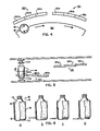
- FIG. 4 a preferred embodiment of the invention at the heat shrinking station F is illustrated.
- a portion of turret 60 is shown and a container 10 with a label 16 applied thereto is also shown.
- Omitted from Figure 4 but shown diagrammatically in Figure 5 are the chucks 110 and 110a.
- Heater assemblies 160 and 161 are provided for shrinking the lower overlap 21 and the upper overlap 20, respectively.
- the assembly 160 comprises three heaters 160a, 160b and 160c which, as shown in Figure 5, are arranged at different elevations, the heater 160a being at the highest elevation, the heater 160b somewhat lower and the heater 160c being at the lowest elevation.
- Heater assembly 161 similarly comprises three heaters 161a, 161b and 161c which are arranged at different elevations as shown.
- the heaters are preferably of the blower type in which a current of air created by release of compressed air is heated by an electric heating element. The speed of the air may be controlled by a valve and the degree of heat may be controlled by a rheostat.
- containers are shown at four different positions in their travel past heater assembly 160.
- the container at the left is shown approaching the heater assembly; the next container is shown opposite heater 160a; and the last container is shown opposite heater 160c.
- the heater 160a directs heat against the film 16 at a level just above the overlap 21, that is to say at approximately the junction of the overlap and the main body portion of the film.
- the heater 160b directs heat against the upper portion of the overlap 21 and the heater 160c directs heat against the lower portion of the overlap 21.
- the arrows indicate the direction of flow of hot air from the heaters 160a, 160b and 160c. Meanwhile the container will be spinning and will have spun at least one revolution while passing each of the heaters 160a, 160b and 160c.
- the heater assemblies 160 and 161 are shown in sequence with the assembly 160 preceding the assembly 161. This order may be reversed and the assembly 160 and 161 may be in vertical alignment. However, a spacing between them is preferred as shown because it has a lesser tendency to overheat the film and the containers, and in particular the glue line applied at the seam of the film. That is, by the time a container and film reach heater assembly 161 much of the heat applied by the preceding heater assembly 160 will have been dissipated.
- the seam at the overlap or freestanding edge (or edges) of the film may have glue applied to it but such is unnecessary.
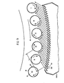
- FIG. 7 the turret 80 is shown in Figure 7 and two blowers 190 (which may be groups of blowers as in Figures 4 and 5) are also shown. Motion of the turret 80 is clockwise and spinning of the containers is also clockwise. Containers 10 with labels 16 applied thereto and having side seams 43 pass by the blowers which, as indicated by the arrows, blow hot air radially inwardly. In Figure 8 containers 10 are shown in four different positions I, II, III and IV as they pass by a blower 190.
- the critical positions insofar as the difficulty above mentioned with the side seam is concerned is the positions at II and III where the side seam is parallel or nearly parallel to the flow of hot air. That is to say at positions II and III the hot air is tangent or nearly tangent to the side seam and it is blowing directly or nearly directly at the glue line 47 (see Figure 2). This softens or melts the glue sufficiently to cause curling and an improper shrinkage of the side seam.
- a modified blower 190A is shown in section having a front cover 191 formed with slanted openings 192.
- the cover 191 may, if desired, be formed by louvres which are adjustable so as to enable one to adjust the angle of the openings 192 and therefore the direction of flow of air from the blower.
- the arrows indicate the direction of the current of hot air.
- position II which is not as critical as position III
- the hot air travels a longer distance before Lmpinging on the side seam than in Figure 8. Also it is oblique to the side seam.
- position III the most critical position
- the container at position IV has its side seam parallel to the flow of hot air but in addition to shielding by the preceding container at position V the hot air has to travel the longer distance "A".
- the clockwise spinning motion of the containers as viewed in Figure 1 has the advantage that when the side seam is exposed to the hot air it is moving away from the source of hot air.
- a suitable angle for the openings 191 in blower 190A is 60° but other angles may be employed provided the angle accomplishes the desired results.
- FIG. 1 Another feature of the invention which aids in the controlled application of heat to the projecting ends 20 and 21 and to the side seams 43 is shown in the form of a shield 200 which is concentric to the turret 80 and which is located inside the turret opposite the containers 10 as they pass by the hotair blowers.
- This shield is held stationary by a bracket or brackets (not shown) which are inserted into the turret between the upper and lower spokes 83 and 85 and which enter the turret between the container input and output points A and G (see Figure 1).
- This shield serves to retain hot air in the shrink area thus making the entire system more energy efficient.
Landscapes
- Engineering & Computer Science (AREA)
- Mechanical Engineering (AREA)
- Manufacturing & Machinery (AREA)
- Lining Or Joining Of Plastics Or The Like (AREA)
- Labeling Devices (AREA)
Abstract
@ Method and apparatus for heat shrinking projecting edges of heat shrinkable (but unshrunken) film onto articles such as cylindrical containers. The film is tightly wrapped around the bodies of the articles and the overlapping ends are held together by glue. The projecting edges of the articles are then heat shrunk onto the shoulders and/or curved lower ends of the bodies as the containers are transported and are caused to spin while being transported. In so doing the hot air is blown in a direction such that it does not blow directly onto the glue at the side seams. This may be accomplished by using a circular, turret type transport and by having blowers which blow hot air obliquely, rather than radially at the articles. Where the articles are closely packed, each article acts to shield the next article when its side seam is parallel to the flow of hot air.
Description
- This invention relates to a machine for and a method of applying heat shrink labels to containers. We have been developing methods of and apparatus for applying heat shrinkable (but unshrunk) film material to articles such as cylindrical containers. In such method a segment of film material having a length slightly greater than the circumference of the article is applied by a conventional labeling procedure as follows: a roll of film material is provided; it is supplied continuously from the roll to a rotating vacuum drum; segments of film are severed between the roll and the vacuum drum and each segment is held on the vacuum drum by vacuum and is transported to a segment applying station; glue is applied to the leading end and to the trailing end of the segment while it is on the vacuum drum; articles such as containers are supplied continuously to the segment applying station in tangent relation to the leading end of-the segments of film material and the leading end of each segment is adhered to the container by glue; and the container is rotated about its cylindrical axis to wrap the segment around it, causing the trailing end to overlap the leading end and to be adhered thereto by means of glue.
- This is a standard labeling operation but differs in that the label material is heat shrinkable material and by reason of the fact that one edge or the other or both edges (hereinafter referred to as "ends") are caused to project beyond the upper end and/or the lower end of the cylindrical body of the container. The or each projecting end is then subjected to heat in the form of a current of hot air to be shrunk onto the container. The main body of the label is not shrunk.
- This invention will be described hereinafter for the most part with reference to the application of labels to cylindrical containers but it will be understood that heat shrinkable film material in general may be applied and that the articles to which they are applied may be other than containers. Also that they need not be cylindrical. This mode of operation results in what is called herein a "side seam", which is the strip where the trailing end of the label overlaps the leading end. The leading end is adhered to the container by glue and the trailing end is adhered to the leading end by glue.
- This invention is directed to solving a problem in connection with the side seams.
- It has been found that, when hot air is applied to the projecting end or ends of the label, the side seam sometimes causes difficulty due, apparently, to the fact that the hot air softens or melts the glue in the side seam. Whatever the cause, the fact is that the side seam tends to curl and an unsightly end product results.
- It is an object of the present invention to provide a solution to this problem.
- According to the present invention there is provided a method of applying heat shrinkable film to articles each of which has a vertical body and an inwardly sloping end portion at at least one end of the body, such method being characterized by cutting segments of such film from a continuously moving length of film, continuously transporting each severed segment to an applicator station, continuously transporting such articles to said applicator station,continuously applying each segment at such applicator station to the body of an article, wrapping it around the article with the trailing end of the segment overlapping the leading end and forming a side seam which is held together by means of an adhesive and in so doing allowing one edge or both edges of the applied segment to project beyond the body portion and to overlie, but to be spaced from, the adjacent inwardly sloping portion or portions of the article; continuing the transport of such articles so wrapped with segments of heat shrinkable film (and meanwhile spinning the containers) through a heating station at which hot air is blown onto the projecting edges to cause them to shrink onto the articles; and so directing,the flow of such hot air from its source onto the projecting edges as to minimize the harmful effect of such flow tangent to the side seams.
- Another aspect of the invention provides apparatus for heat shrinking heat shrinkable film onto articles each of which has a vertical body and at least one end portion sloping inwardly from the body, each such article being tightly wrapped with a heat shrinkable but unshrunken film, the leading end of which overlaps the trailing end to form a side seam which is held together by means of glue, said film projecting beyond the body portion at at least one edge and lying opposite but unattached to such sloping portion or portions, said apparatus being characterized by the provision of means for continuously transporting such articles so wrapped with segments through a heating station; means for applying a current of hot air at such heating station to the projecting edge portion or portions of the film to heat shrink the same without heat shrinking the major part of the body portion of the film; and means for so directing the flow of hot air from its source as to minimize the harmful effect of hot air when blown paralled to the side seams.
- The invention will now be described in greater detail and by way of example with reference to the accompanying drawings, in which:
- Figure 1 is a diagrammatic view of a labeling and heat shrinking operation using the method of the invention;
- Figure 2 is a fragmentary, horizontal cross section through a container and the applied film showing the side seam;
- Figure 3 is a vertical cross section through a container transport employed for transporting containers to the labeling station, rotating the containers to wrap labels around them and moving the rotating containers past hot air blowers to accomplish shrinking of the projecting end or ends of the label;
- Figure 4 is a diagrammatic view from above of a preferred arrangement of hot air blowers;
- Figure 5 is a view in front elevation of the blower system of Figure 4:
- Figures 6A, 6B, 6C and 6D are views of a container in various stages of application of a label thereto, Figure 6A shows a label applied to a container and with projecting ends, Figures 6B,6C and 6D showing successive stages in heat shrinking the lower projecting end of the label;
- Figure 7 is a fragmentary diagrammatic view of the turret and of containers transported by the turret past the heat shrinking station;
- Figure 8 is a similar view on an enlarged scale illustrating the nature of the problem mentioned above;
- Figure 9 is a view similar to that of Figure 8 but showing the manner in which this problem is solved in accordance with the present invention.
- A container with a heat shrink label applied thereto, and the side seam which causes the difficulty mentioned above will first be described with reference to Figure 6A and Figure 2.
- Referring to Figure 6A, a container is shown which is generally designated by the
reference numeral 10 and which may be of plastic (e.g. PET, which stands for polyethylene terephthalate), glass or any other suitable material and which has a cylindrical body 11, aneck 12, an inwardly slopingportion 13 connecting body portion 11 with the bottom of the container and a connectingportion 14 connecting the body portion 11 with theneck 12. The label is generally indicated by thereference numeral 16 and as will be seen it is wrapped around and tightly applied to the container, and it has a length from top to bottom greater than the length of the body portion 11 of the container such that there are two projecting end portions, namely theupper end portion 20 which is opposite and stands free of theshoulder portion 14 and a lower portion 21 which stands opposite but is free from thelower portion 13. - Referring now to Figure 2 a fragment of a
label 16 is shown applied to acontainer 10 and forming aside seam 43. This is formed by thetrailing end 44 of the label and the leadingend 45 of the label, there being a layer ofhot melt glue 46 between the leading end and the container and another layer ofhot melt glue 47 between the trailing end and the leading end. It is this seam which causes the difficulty to which this invention is particularly directed. - Referring now to Figure 1, a complete assembly, such as a labeling assembly, is shown. It comprises a
roll 50 of heat shrink film 51 (e.g. label stock), adrive roller 52 and a pinch roller 53, a cutter 54 and avacuum drum 55. These elements are of known construction and mode of operation. Other elements not shown may be included, e.g. tensioning means for thelabel stock 51. Aglue applicator 56 of known construction is also shown which applies hot melt glue to the leading end and the trailing end of each label. - The
glue applicator 56 may be a rotating member which dips into a pot of hot melt glue (not shown) and it may be caused to oscillate as well as rotate in timed relation to the rotation of thevacuum drum 55 to apply a layer ofglue 46 to the leading end of each label and a layer ofglue 47 to the trailing end of each label. Alternatively thedrum 55 may be formed with raised areas which are spaced so that the leading and trailing ends of the label are elevated from the main surface of the drum and are contacted by aglue applicator 56 which rotates but does not oscillate. Both types of glue applicator systems are well known. - Also shown is a
turret 60 rotating about anaxis 61 which receivescontainers 10 from a container feed (not shown). Theturret 60 is provided with pairs of chucks such as those shown at 110 and 110a in Figure 3. Each container, in turn, is clamped between a pair of chucks and is transported orbitally about theaxis 61 ofturret 60 and is caused to spin about its own cylindrical axis. A glue line may be applied to each container such as that shown at 53 in Figure 1 of my U. S. Patent 4,108,710. However, it is preferred to apply the glue to the leading and trailing ends of the label. It will be understood that the various driven elements are coordinated and synchronized to accomplish the desired results. - Each severed
label 66 is gripped byvacuum drum 55 and is rotated counterclockwise as viewed in Figure 5 past theglue applicator 56 which applies glue to the leading and trailing ends of each label. Preferably as described in my U. S. Patent No. 3,765,991 the leading end of thelabel stock 51 is gripped by thevacuum drum 55 before a label is severed. Also thedrum 55 is rotated at a surface speed greater than the speed at which the label stock is fed by therollers 52 and 53. The label then proceeds to a labeling station D. The leading end of each label is adhered to the container at which time vacuum is released and the label commences to wrap around the spinning container until the glued trailing end overlaps and is adhered to the leading end of the label. If a partial wrap is to be applied, the glued trailing end will be adhered directly to the container. This wrapping is aided by an arcuate guard andpressure member 70 which is concentric to thecontainer turret 60 and is spaced from theturret axis 61 so that it will restrain the loose end of the label until it is wrapped around the container. Theguard 70 may be a brush or made of rubber or other material which does not mar the label. _It need not extend above or below the cylindrical body portion of the container. Preferably theguard 70 is formed with a groove or channel (not shown) facing the label and the container which has a width equal to the width of the label. This design ensures that, regardless of irregularities in the containers or other disturbing factors, the leading andtrailing ends - A pressure roller 71 is provided to apply pressure to the side seam so that it is firm and even. This roller may be made of metal, plastic, rubber or other suitable material and it is rotated at a surface speed which is the same as or slightly slower than the surface speed of the container. The use of a slightly slower speed causes a pull or tension which is desirable.
- This mode of operation results in the formulation of a side seam such as shown at 43 in Figure 2. As described in the aforesaid copending applications, glue may be applied at 46 and 47 the entire length of the label including the projecting
end portions 20 and 21 or it may be applied only to that portion of the label which is adhered-to and is in contact with the body portion 11 of the container. - Also shown in Figure 1 is a
hot air blower 72 which directs hot air at the projecting end portion orend portions 20 and 21 of the label to cause it (or them) to shrink onto the container. - Referring now to Figure 3, a preferred type of apparatus is shown for transporting containers from point A to point G in Figure 1. The apparatus embodies extensible-
retractable tongues 119 and 119A (see below). As described in copending application Serial No. 438,386 the tongues, when extended, lie between the projecting ends 20 and 21 of the label and the container and serve as continuations of the body portion 11 of the container to facilitate the application of glue to the entire length of theside seam 43. Alternatively, as described in copending application Serial No. 471,655 these tongues, when extended, lie outside the label and serve as heat shields and also to urge the projectingportions 20 and 21 against the container. In the present invention either of these embodiments may be employed or thetongues 119 and 119A may be omitted altogether. - By way of example, the embodiment shown in Figure 3, which is the subject of copending application Serial No. 438,386 is illustrated as an embodiment of the present invention.
- Referring now to Figure 3 a turret assembly is there shown and is generally designated by the
reference numeral 80. Amain shaft 81 is shown which is journalled in a frame 82 and mounted to rotate with it are a number of arms orspokes 83 which are integral with a hub 83a which is fixed to theshaft 81 to rotate with it. Rotatably mounted on the hub 83a is aplate 84 which is mounted on hub 83a by means ofbearings 85. Theplate 84 is fixed by suitable means (not shown) against rotation so that theshaft 81 and parts operated by it may rotate about the axis of theshaft 81 while theplate 84 and parts supported by it are stationary. - The
plate 84 supports abracket 86 which in turn supports an arcuatecontinuous cam 87. At its outer edge theplate 84 is formed with abracket 88, which supports a continuousarcuate cam 89. Theplate 84 also supportspins 90 which form a gear to drive sprockets as described hereinafter.Lower arms 95 are provided which are fixed to and rotate with theshaft 81 and support a cam 89a and pins 90a which are comparable to and serve a similar purpose as thecam 89 and pins 90. - A chuck assembly is provided which includes a
collar 99 which is connected by abracket 100 to abar 101 which in turn supports arail 102 of angular cross-section. Abracket 103 connected to thespoke 83supports rollers 104 which have grooved peripheries which ride upon therail 102. At its upper end therail 102 supports acam follower roller 105 which rides on thecam 87. Achuck 110 is provided which is shaped so that it will fit snugly over the crown of acontainer 10. This chuck is carried by a hub 111 which forms the inner race forroller bearings 112, the outer race of which is provided by thecollar 99. Attached to the upper end of the hub 111 is a sprocket 113 which meshes with thepins 90 and serves to rotate thechuck 110. The hub 111 is hollow, being formed with anaxial passage 114 in which apin 115 having a rounded upper end is slidable. The rounded upper end of thepin 115 bears against thecam 89. Apin 116 extends upwardly from thechuck 110 and aspring 117 lodged within thetubular passage 114 and seated on thepin 116 serves to hold the rounded upper end of thepin 115 at all times against thecam 89. - A
bracket 118 is provided which is fixed to thepin 115 and which supports atongue 119 which extends downwardly and has a taperedtip 120. The tongue passes through anopening 121 in thechuck 110. The taper of thetip 120 conforms to the surface of the container at the junction of the shoulder with the cylindrical body of the container. - A chuck assembly 98a is provided at the bottom and is supported by the
plate 95. Parts similar to parts in the chuck assembly 98 are similarly numbered with the addition of the letter "a". The construction and operation will be evident from the description above of the chuck assembly 98 except that there is nocam 87,cam follower 105 and associated parts, the reason being that the lower chuck assembly 98a is not elevated and lowered as is the upper chuck assembly 98. - It will be understood that each pair of arms or
spokes - It will be apparent that as the
shaft 81 rotates each of the chuck assemblies 98 and 98a will rotate orbitally with theshaft 81 about the axis thereof. It will also be apparent as more fully described hereinafter that the upper chuck assembly 98 and with it thechuck 110 are caused periodically to elevate by reason of thecam 87 and thecam follower roller 105 and the supporting mechanism described above and illustrated in Figure 3 and that meanwhile thechuck 110 will be caused to rotate about its own axis by reason of the sprocket 113 and pins 90. It will also be apparent that thetongue 119 will undergo periodic elevation (retraction) and lowering (extension) by reason of engagement of thepin 115 with thecam 89. It will similarly be apparent that the lower chuck assembly 98a will rotate orbitally with theshaft 81; that thelower chuck 110a will rotate about its own axis; and that thetongue 119a will undergo periodic elevation (extension) and lowering (retraction). - Referring to Figure 1 as well as to Figure 3, the profile of the
cam 87 is such that eachupper chuck 110 is in elevated position at the station marked B in Figure 1 where a container enters the turret so as to clear the crown of the container. The container is seated on thelower chuck 110a. Then thecam 87 and thecam roller 105 will cause thebar 101 andbracket 100 to lower thereby contacting therespective chuck 110 with the crown of 'the container and clamping the container between the upper and lower chucks and causing the container to spin. This driving relationship between thechucks container 10 will continue through the stations indicated as C, D, E and F in Figure 1 and then theupper chuck 110 will be elevated to free the container which will be extracted by suitable extraction mechanism (not shown) such as, for example, a star wheel. - Adjustments for containers of different heights and different shapes can be readily made. For example hub 83a may be raised or lowered and chucks 110 and 110a may be changed.
- The manner in which the
tongues 119 and 119A operate and the functions they perform are described in my copending applications Serial Nos. 438,386 and 471,655 which are incorporated herein by reference. Either such embodiment may be employed in the practice of the present invention or some other embodiment, e.g. theturret assembly 80 of Figure 3 without thetongues 119 and 119A (and their operating mechanisms), may be employed. - A preferred method of applying hot air in successive stages is illustrated in Figures 4, 5 and 6, which will now be described.
- Referring now to Figures 4, 5 and 6, a preferred embodiment of the invention at the heat shrinking station F is illustrated. A portion of
turret 60 is shown and acontainer 10 with alabel 16 applied thereto is also shown. Omitted from Figure 4 but shown diagrammatically in Figure 5 are thechucks -
Heater assemblies upper overlap 20, respectively. Theassembly 160 comprises threeheaters heater 160a being at the highest elevation, theheater 160b somewhat lower and theheater 160c being at the lowest elevation.Heater assembly 161 similarly comprises threeheaters - Referring to Figure 6, containers are shown at four different positions in their travel past
heater assembly 160. The container at the left is shown approaching the heater assembly; the next container is shownopposite heater 160a; and the last container is shownopposite heater 160c. Theheater 160a directs heat against thefilm 16 at a level just above the overlap 21, that is to say at approximately the junction of the overlap and the main body portion of the film. Theheater 160b directs heat against the upper portion of the overlap 21 and theheater 160c directs heat against the lower portion of the overlap 21. The arrows indicate the direction of flow of hot air from theheaters heaters - A similar procedure occurs at the
upper overlap 20 as the container passes theheaters overlap 20 will be shrunk byheater 160a at approximately the junction of the overlap 21 and the main body portion of the film, then shrinking will occur upwardly of this level and finally the edge of the overlap 21 will be shrunk onto the roundedportion 14 of the container thereby accomplishing the same effect as described above with reference to theheaters - The
heater assemblies assembly 160 preceding theassembly 161. This order may be reversed and theassembly heater assembly 161 much of the heat applied by the precedingheater assembly 160 will have been dissipated. - The seam at the overlap or freestanding edge (or edges) of the film may have glue applied to it but such is unnecessary.
- Referring now to Figures 7 and 8, the
turret 80 is shown in Figure 7 and two blowers 190 (which may be groups of blowers as in Figures 4 and 5) are also shown. Motion of theturret 80 is clockwise and spinning of the containers is also clockwise.Containers 10 withlabels 16 applied thereto and havingside seams 43 pass by the blowers which, as indicated by the arrows, blow hot air radially inwardly. In Figure 8containers 10 are shown in four different positions I, II, III and IV as they pass by ablower 190. - I have found that the critical positions insofar as the difficulty above mentioned with the side seam is concerned is the positions at II and III where the side seam is parallel or nearly parallel to the flow of hot air. That is to say at positions II and III the hot air is tangent or nearly tangent to the side seam and it is blowing directly or nearly directly at the glue line 47 (see Figure 2). This softens or melts the glue sufficiently to cause curling and an improper shrinkage of the side seam.
- Referring now to Figure 9, a modified blower 190A is shown in section having a
front cover 191 formed with slantedopenings 192. Thecover 191 may, if desired, be formed by louvres which are adjustable so as to enable one to adjust the angle of theopenings 192 and therefore the direction of flow of air from the blower. - The arrows indicate the direction of the current of hot air. At position II (which is not as critical as position III) the hot air travels a longer distance before Lmpinging on the side seam than in Figure 8. Also it is oblique to the side seam. In position III (the most critical position) not only does the hot air travel farther but the side seam of the container at position III is shielded by the preceding container at IV. The container at position IV has its side seam parallel to the flow of hot air but in addition to shielding by the preceding container at position V the hot air has to travel the longer distance "A".
- The clockwise spinning motion of the containers as viewed in Figure 1 has the advantage that when the side seam is exposed to the hot air it is moving away from the source of hot air.
- A suitable angle for the
openings 191 in blower 190A is 60° but other angles may be employed provided the angle accomplishes the desired results. - Referring again to Figure 1, another feature of the invention which aids in the controlled application of heat to the projecting ends 20 and 21 and to the side seams 43 is shown in the form of a
shield 200 which is concentric to theturret 80 and which is located inside the turret opposite thecontainers 10 as they pass by the hotair blowers. This shield is held stationary by a bracket or brackets (not shown) which are inserted into the turret between the upper andlower spokes
Claims (9)
1. A method of applying heat shrinkable film to articles each of which has a vertical body and an inwardly sloping end portion at at least one end of the body, such method being characterized by cutting segments of such film from a continuously moving length of film; continuously transporting each severed segment to an applicator station; continuously transporting such articles to said applicator station; continuously applying each segment at such applicator station to the body of an article, wrapping it around the article with the trailing end of the segment overlapping the leading end and forming a side seam which is held together by means of an adhesive and in so doing allowing one edge or both edges of the applied segment to project beyond the body portion and to overlie, but to be spaced from, the adjacent inwardly sloping portion or portions of the article; continuing the transport of such articles so wrapped with segments of heat shrinkable film (and meanwhile spinning the containers) through a heating station at which hot air is blown onto the projecting edges to cause them to shrink onto the articles; and so directing the flow of such hot air from its source onto the projecting edges as to minimize the harmful effect of such flow tangent to the side seams.
2. A method according to claim 1, characterized in that the articles with film wrapped around them are transported in a circular path through the heating station and hot air is blown onto the projecting edges in an oblique, non radial direction.
3. A method according to claim 2,characterized in that the articles during such transport through the heating station are caused to spin in a direction such that as each side seam reaches a position parallel to the flow of hot air it is receding from the source of hot air.
4. A method according to claim 2, characterized in that articles during transit through the heating station are sufficiently close to one another that each article shields the next article when its side seam approaches a position in which its side seam is parallel to the direction of flow of hot air.
5. Apparatus for heat shrinking heat shrinkable film onto articles each of which has a vertical body and at least one end portion sloping inwardly from the body, each such article being tightly wrapped with a heat shrinkable but unshrunken film, the leading end of which overlaps the trailing end to form a side seam which is held together by means of glue, said film projecting beyond the body portion at at least one edge and lying opposite but unattached to such sloping portion or portions, said apparatus being characterized by the provision of means for continuously transporting such articles so wrapped with segments through a heating station; means for applying a current of hot air at such heating station to the projecting edge portion or portions of the film to heat shrink the same without heat shrinking the major part of the body portion of the film; and means for so directing the flow of hot air from its source as to minimize the harmful effect of hot air when blown parallel to the side seams.
6. The apparatus of claim 5, characterized in that said means for directing the flow of air comprises one or more blowers which blow hot air obliquely at the articles.
7. The apparatus of claim 6, characterized in that the means for continuously transporting the articles is arranged to transport them through in a circular path and the or each blower is arranged to direct hot air in a non-radial direction.
8. The apparatus of claim 7, characterized in that the transporting means is in the form of a turret and adapted to transport articles so closely spaced that each article as it passes through the heating station shields the following article when the side seam of the following article is parallel to the direction of flow of hot air.
9. The apparatus of claim 8, characterized by a heat shield within the turret on the sides of the articles remote from the heating station, said shield acting to cause rebound of hot air and to conserve energy.
Applications Claiming Priority (2)
| Application Number | Priority Date | Filing Date | Title |
|---|---|---|---|
| US06/519,267 US4545832A (en) | 1982-05-27 | 1983-08-01 | Machine and method for applying heat shrink labels |
| US519267 | 1995-08-25 |
Publications (2)
| Publication Number | Publication Date |
|---|---|
| EP0134689A2 true EP0134689A2 (en) | 1985-03-20 |
| EP0134689A3 EP0134689A3 (en) | 1985-05-29 |
Family
ID=24067556
Family Applications (1)
| Application Number | Title | Priority Date | Filing Date |
|---|---|---|---|
| EP84305139A Ceased EP0134689A3 (en) | 1983-08-01 | 1984-07-27 | Machine and method for applying heat shrink labels |
Country Status (7)
| Country | Link |
|---|---|
| US (1) | US4545832A (en) |
| EP (1) | EP0134689A3 (en) |
| JP (1) | JPS6058834A (en) |
| AU (1) | AU3094684A (en) |
| CA (1) | CA1254498A (en) |
| ES (1) | ES8601786A1 (en) |
| ZA (1) | ZA845710B (en) |
Cited By (8)
| Publication number | Priority date | Publication date | Assignee | Title |
|---|---|---|---|---|
| EP0525729A1 (en) * | 1991-08-01 | 1993-02-03 | KRONES AG Hermann Kronseder Maschinenfabrik | Method of and apparatus for applying labels of sealable material to containers and containers so labelled |
| GB2262731A (en) * | 1991-12-23 | 1993-06-30 | Owens Illinois Plastic Prod | Applying labels to containers |
| GB2294920A (en) * | 1991-12-23 | 1996-05-15 | Owens Illinois Plastic Prod | Applying labels to containers |
| US5746041A (en) * | 1996-09-17 | 1998-05-05 | Ossid Corporation | Shrinking selected portions of film wrapped around a product |
| EP0954476A4 (en) * | 1995-10-23 | 1999-11-10 | ||
| US7156528B2 (en) | 2004-01-21 | 2007-01-02 | 3M Innovative Properties Company | Retroreflective elements and articles |
| US7168815B2 (en) | 2004-01-21 | 2007-01-30 | 3M Innovative Properties Company | Retroreflective elements and articles |
| EP1935791A1 (en) * | 2006-12-20 | 2008-06-25 | Krones AG | Machine and method for shrinking a heat-shrink foil on products to be packaged. |
Families Citing this family (37)
| Publication number | Priority date | Publication date | Assignee | Title |
|---|---|---|---|---|
| US4663106A (en) * | 1984-05-01 | 1987-05-05 | Kimberly-Clark Corporation | Formation of elasticized portions of disposable garments and other articles |
| US4806197A (en) * | 1987-02-18 | 1989-02-21 | Dinagraphics, Inc. | Continuous motion round bottle turret |
| US4876123A (en) * | 1988-06-27 | 1989-10-24 | Minnesota Mining And Manufacturing Company | Tamper indicating tape and delaminating film therefore |
| US4922683A (en) * | 1988-11-10 | 1990-05-08 | Austin-Gordon Design, Inc. | Shrink banding machine |
| US5271783A (en) * | 1990-01-12 | 1993-12-21 | B & H Manufacturing Co., Inc. | Method and apparatus for heat sealing labels on containers |
| DE4025410C1 (en) * | 1990-08-10 | 1991-09-26 | Krones Ag Hermann Kronseder Maschinenfabrik, 8402 Neutraubling, De | |
| US5464495A (en) * | 1991-08-01 | 1995-11-07 | Krones Ag Hermann Kronseder Maschinenfabrik | Method and apparatus for applying labels to containers and containers resulting therefrom |
| US5390477A (en) * | 1991-11-19 | 1995-02-21 | Mcneilab, Inc. | System for applying a heat shrinkable sleeve to a container |
| US5405487A (en) * | 1992-06-30 | 1995-04-11 | Cms Gilbreth Packaging Systems, Inc. | Apparatus and method for applying labels onto small cylindrical articles and web and adhesive delivery mechanism |
| US5399216A (en) * | 1992-06-30 | 1995-03-21 | Cms Gilbreth Packaging Systems | Apparatus and method for applying labels onto small cylindrical articles using pressure applicator to prevent label mismatching |
| US5344519A (en) * | 1992-06-30 | 1994-09-06 | Cms Gilbreth Packaging Systems | Apparatus for applying labels onto small cylindrical articles having improved vacuum and air pressure porting for label transport drum |
| US5350482A (en) * | 1992-06-30 | 1994-09-27 | Cms Gilbreth Packaging Systems | Apparatus and method for applying labels onto small cylindrical articles |
| US5401353A (en) * | 1992-06-30 | 1995-03-28 | Cms Gilbreth Packaging Systems | Apparatus and method for applying labels onto small cylindrical articles using static wipers |
| US5458728A (en) * | 1994-06-27 | 1995-10-17 | Galchefski; John | Apparatus and method for applying labels onto small cylindrical articles with improved seam formation by retarded article rotation |
| AU3552995A (en) * | 1994-09-19 | 1996-04-09 | Cms Gilbreth Packaging Systems, Inc. | Labelling machine |
| US5538575A (en) * | 1994-10-21 | 1996-07-23 | Cms Gilbreth Packaging Systems | Labelling machine and method for applying adhesive to labels for attachment to containers and article therefore |
| US5779835A (en) * | 1994-11-21 | 1998-07-14 | Cms Gilbreth Packaging Systems, Inc. | Method and apparatus for applying labels to articles using bottom feed chain conveyor |
| US5480502A (en) * | 1994-11-21 | 1996-01-02 | Cms Gilbreth Packaging Systems, Inc. | Method and apparatus for applying labels to articles using cooling air on label receiving positions |
| US5749990A (en) * | 1994-11-21 | 1998-05-12 | Cms Gillbreth Packaging Systems, Inc. | Method and apparatus for applying labels to articles using bottom feed conveying unit |
| US5863382A (en) * | 1995-09-22 | 1999-01-26 | Trine Manufacturing Company, Inc. | Labeling machine with improved cutter assembly |
| US6048423A (en) * | 1997-05-28 | 2000-04-11 | The Coca-Cola Company | Labeling process and apparatus |
| US6450230B1 (en) | 1999-06-24 | 2002-09-17 | S-Con, Inc. | Labeling apparatus and methods thereof |
| US6328832B1 (en) | 1998-06-26 | 2001-12-11 | S-Con, Inc. | Labeling apparatus with web registration, web cutting and carrier mechanisms, and methods thereof |
| GB2334851B (en) * | 1999-02-08 | 2000-01-12 | Joseph Harold Stephens | A loudspeaker/microphone |
| US7422781B2 (en) * | 2003-04-21 | 2008-09-09 | 3M Innovative Properties Company | Tamper indicating devices and methods for securing information |
| US20080050651A1 (en) * | 2004-05-18 | 2008-02-28 | Mutsumi Wakai | Multilayer Heat Shrinkable Film and Wrapped Battery |
| US7875143B2 (en) * | 2006-01-20 | 2011-01-25 | Gerroplast Gmbh | Method and apparatus for labeling containers |
| US20070175574A1 (en) * | 2006-01-27 | 2007-08-02 | Douglas Crank | Apparatus and method for conforming a label to the contour of a container |
| US20080271833A1 (en) * | 2007-04-24 | 2008-11-06 | Tennant Matthew A | Personalizing device and method |
| IT1396834B1 (en) | 2009-11-18 | 2012-12-14 | Sacmi Labelling S P A Ora Sacmi Verona S P A | PROCEDURE FOR THE PRODUCTION OF SLEEVE LABELS AND DEVICE FOR THEIR PRODUCTION. |
| IT1396835B1 (en) * | 2009-11-18 | 2012-12-14 | Sacmi Labelling S P A Ora Sacmi Verona S P A | PROCEDURE FOR THE PRODUCTION OF SLEEVE LABELS AND DEVICE FOR THEIR PRODUCTION. |
| DE102013103111A1 (en) * | 2013-03-26 | 2014-10-02 | George Robert Collins | Holder for a container receptacle and container receptacle |
| US9963260B2 (en) | 2014-04-14 | 2018-05-08 | Altria Client Services Llc | Rotatable drum and method and system using the same for the automated production of E-vapor devices |
| US11576440B2 (en) | 2014-04-14 | 2023-02-14 | Altria Client Services Llc | Method and system for the automated production of e-vapor devices |
| CN106793837A (en) | 2014-10-16 | 2017-05-31 | 奥驰亚客户服务有限责任公司 | Assembling drum, system and its application method for automated production electronic cigarette device |
| US10858137B2 (en) | 2014-12-19 | 2020-12-08 | Altria Client Services Llc | System and method for applying a label for the automated production of e-vapor devices |
| CN113022979A (en) * | 2021-01-18 | 2021-06-25 | 北京三快在线科技有限公司 | Packaging device and food processing equipment |
Citations (5)
| Publication number | Priority date | Publication date | Assignee | Title |
|---|---|---|---|---|
| GB1332895A (en) * | 1970-09-28 | 1973-10-10 | Id Packaging Ltd | Shrink wrapping ovens |
| GB1485942A (en) * | 1976-03-02 | 1977-09-14 | Owens Illinois Inc | Method and apparatus for producing plastic-covered containers |
| US4172873A (en) * | 1978-07-03 | 1979-10-30 | Owens-Illinois, Inc. | Method for applying a heat shrinkable sleeve to a plastic bottle |
| GB2088819A (en) * | 1980-10-24 | 1982-06-16 | Sun Chemical Corp | Labelling machine |
| US4406721A (en) * | 1982-05-27 | 1983-09-27 | B & H Manufacturing Company, Inc. | System and apparatus for applying heat shrink film to containers and other articles and heat shrinking the same |
Family Cites Families (6)
| Publication number | Priority date | Publication date | Assignee | Title |
|---|---|---|---|---|
| US4108710A (en) * | 1972-02-14 | 1978-08-22 | B & H Manufacturing Company, Inc. | Apparatus for applying labels to containers |
| CA1012906A (en) * | 1973-06-26 | 1977-06-28 | Hubert J. Germiat | Film labeled metal container and method therefor |
| CH590760A5 (en) * | 1975-01-03 | 1977-08-31 | Rausing Anders Ruben | |
| US4072553A (en) * | 1976-03-31 | 1978-02-07 | Owens-Illinois, Inc. | Apparatus controlling shrinkage of a sleeve wrap on a container |
| US4092382A (en) * | 1976-03-31 | 1978-05-30 | Owens-Illinois, Inc. | Method of heat shrinking thermoplastic sleeve wraps on glass containers |
| CH646398A5 (en) * | 1980-03-28 | 1984-11-30 | Obrist Ag Albert | METHOD AND DEVICE FOR SCREWING ON A CAP FROM PLASTIC MATERIAL ON A CONTAINER MOUNT. |
-
1983
- 1983-08-01 US US06/519,267 patent/US4545832A/en not_active Expired - Lifetime
-
1984
- 1984-07-23 AU AU30946/84A patent/AU3094684A/en not_active Abandoned
- 1984-07-24 ZA ZA845710A patent/ZA845710B/en unknown
- 1984-07-27 EP EP84305139A patent/EP0134689A3/en not_active Ceased
- 1984-07-31 JP JP59159497A patent/JPS6058834A/en active Granted
- 1984-07-31 ES ES534754A patent/ES8601786A1/en not_active Expired
- 1984-08-01 CA CA000460169A patent/CA1254498A/en not_active Expired
Patent Citations (5)
| Publication number | Priority date | Publication date | Assignee | Title |
|---|---|---|---|---|
| GB1332895A (en) * | 1970-09-28 | 1973-10-10 | Id Packaging Ltd | Shrink wrapping ovens |
| GB1485942A (en) * | 1976-03-02 | 1977-09-14 | Owens Illinois Inc | Method and apparatus for producing plastic-covered containers |
| US4172873A (en) * | 1978-07-03 | 1979-10-30 | Owens-Illinois, Inc. | Method for applying a heat shrinkable sleeve to a plastic bottle |
| GB2088819A (en) * | 1980-10-24 | 1982-06-16 | Sun Chemical Corp | Labelling machine |
| US4406721A (en) * | 1982-05-27 | 1983-09-27 | B & H Manufacturing Company, Inc. | System and apparatus for applying heat shrink film to containers and other articles and heat shrinking the same |
Cited By (15)
| Publication number | Priority date | Publication date | Assignee | Title |
|---|---|---|---|---|
| EP0525729A1 (en) * | 1991-08-01 | 1993-02-03 | KRONES AG Hermann Kronseder Maschinenfabrik | Method of and apparatus for applying labels of sealable material to containers and containers so labelled |
| GB2262731A (en) * | 1991-12-23 | 1993-06-30 | Owens Illinois Plastic Prod | Applying labels to containers |
| GB2294920A (en) * | 1991-12-23 | 1996-05-15 | Owens Illinois Plastic Prod | Applying labels to containers |
| GB2262731B (en) * | 1991-12-23 | 1996-09-04 | Owens Illinois Plastic Prod | Apparatus for applying labels to containers |
| GB2294920B (en) * | 1991-12-23 | 1996-09-04 | Owens Illinois Plastic Prod | Apparatus for applying labels to containers |
| EP0954476A4 (en) * | 1995-10-23 | 1999-11-10 | ||
| EP0954476A1 (en) * | 1995-10-23 | 1999-11-10 | B & H MANUFACTURING COMPANY, INC. | Applying stretched labels to cylindrical containers |
| EP1431188A1 (en) * | 1995-10-23 | 2004-06-23 | B & H MANUFACTURING COMPANY, INC. | Applying stretched labels to cylindrical containers |
| US5746041A (en) * | 1996-09-17 | 1998-05-05 | Ossid Corporation | Shrinking selected portions of film wrapped around a product |
| US7156528B2 (en) | 2004-01-21 | 2007-01-02 | 3M Innovative Properties Company | Retroreflective elements and articles |
| US7168815B2 (en) | 2004-01-21 | 2007-01-30 | 3M Innovative Properties Company | Retroreflective elements and articles |
| US7413316B2 (en) | 2004-01-21 | 2008-08-19 | 3M Innovative Properties Company | Retroreflective elements and articles |
| US7458693B2 (en) | 2004-01-21 | 2008-12-02 | 3M Innovative Properties Company | Retroreflective elements and articles |
| EP1935791A1 (en) * | 2006-12-20 | 2008-06-25 | Krones AG | Machine and method for shrinking a heat-shrink foil on products to be packaged. |
| US7891157B2 (en) | 2006-12-20 | 2011-02-22 | Krones Ag | Machine for shrink-fitting of shrink wrap film onto packages |
Also Published As
| Publication number | Publication date |
|---|---|
| CA1254498A (en) | 1989-05-23 |
| AU3094684A (en) | 1985-02-07 |
| JPH0472687B2 (en) | 1992-11-18 |
| US4545832A (en) | 1985-10-08 |
| ZA845710B (en) | 1985-03-27 |
| EP0134689A3 (en) | 1985-05-29 |
| JPS6058834A (en) | 1985-04-05 |
| ES534754A0 (en) | 1985-11-16 |
| ES8601786A1 (en) | 1985-11-16 |
Similar Documents
| Publication | Publication Date | Title |
|---|---|---|
| US4545832A (en) | Machine and method for applying heat shrink labels | |
| US4416714A (en) | Labeling machine for heat shrink labels | |
| US4406721A (en) | System and apparatus for applying heat shrink film to containers and other articles and heat shrinking the same | |
| US5403635A (en) | System for applying heat shrink film to containers and other articles and heat shrinking the same | |
| US5403416A (en) | Method of labeling containers with convex surfaces | |
| US4844957A (en) | System for applying heat shrink film to containers and other articles and heat shrinking the same | |
| US4704173A (en) | System for applying heat shrink film to containers and other articles and heat shrinking the same | |
| US4977002A (en) | System for applying heat shrink film to containers and other articles and heat shrinking the same | |
| US4111738A (en) | Apparatus for producing shrunken pilfer-proof neck labels for containers | |
| US5491010A (en) | Container with a label adhered to the container | |
| US20060048417A1 (en) | Article with a labeled lateral surface and device for labeling an article | |
| US5137596A (en) | Apparatus for heat sealing labels on containers | |
| CA2074921C (en) | Cylindrical body label wrapping system with cam operated adjustable path length retractable heaters | |
| GB2194504A (en) | Labelling | |
| US5522960A (en) | Method and apparatus for applying labels to tapered articles | |
| EP0095882B1 (en) | A method of and apparatus for applying labels of heat shrink material to articles and articles so wrapped | |
| JPS644901B2 (en) | ||
| US4011122A (en) | Method for producing plastic-covered containers | |
| US5271783A (en) | Method and apparatus for heat sealing labels on containers | |
| US20110247745A1 (en) | Method and device for equipping containers | |
| NZ217648A (en) | Apparatus for applying heat activatable adhesive labels to containers | |
| JPH0352336B2 (en) | ||
| EP0485184A1 (en) | Method and apparatus for applying wrap-around labels to containers | |
| US4021286A (en) | Apparatus for producing shrunken pilfer-proof neck labels for containers | |
| CA1233766A (en) | Apparatus for applying heat shrink labels and end product made thereby |
Legal Events
| Date | Code | Title | Description |
|---|---|---|---|
| PUAI | Public reference made under article 153(3) epc to a published international application that has entered the european phase |
Free format text: ORIGINAL CODE: 0009012 |
|
| AK | Designated contracting states |
Designated state(s): BE DE FR GB IT |
|
| PUAL | Search report despatched |
Free format text: ORIGINAL CODE: 0009013 |
|
| AK | Designated contracting states |
Designated state(s): BE DE FR GB IT |
|
| 17P | Request for examination filed |
Effective date: 19851030 |
|
| 17Q | First examination report despatched |
Effective date: 19860423 |
|
| STAA | Information on the status of an ep patent application or granted ep patent |
Free format text: STATUS: THE APPLICATION HAS BEEN REFUSED |
|
| 18R | Application refused |
Effective date: 19871126 |
|
| RIN1 | Information on inventor provided before grant (corrected) |
Inventor name: HOFFMANN, WOLFGANG |