EP0134656A2 - Vorrichtung zur Entschleierung geschützter Fernsehbilder - Google Patents
Vorrichtung zur Entschleierung geschützter Fernsehbilder Download PDFInfo
- Publication number
- EP0134656A2 EP0134656A2 EP84304655A EP84304655A EP0134656A2 EP 0134656 A2 EP0134656 A2 EP 0134656A2 EP 84304655 A EP84304655 A EP 84304655A EP 84304655 A EP84304655 A EP 84304655A EP 0134656 A2 EP0134656 A2 EP 0134656A2
- Authority
- EP
- European Patent Office
- Prior art keywords
- unscrambling
- signal
- scrambled
- pattern
- control signal
- Prior art date
- Legal status (The legal status is an assumption and is not a legal conclusion. Google has not performed a legal analysis and makes no representation as to the accuracy of the status listed.)
- Granted
Links
Images



Classifications
-
- H—ELECTRICITY
- H04—ELECTRIC COMMUNICATION TECHNIQUE
- H04N—PICTORIAL COMMUNICATION, e.g. TELEVISION
- H04N7/00—Television systems
- H04N7/16—Analogue secrecy systems; Analogue subscription systems
- H04N7/167—Systems rendering the television signal unintelligible and subsequently intelligible
- H04N7/171—Systems operating in the amplitude domain of the television signal
- H04N7/1716—Systems operating in the amplitude domain of the television signal by inverting the polarity of active picture signal portions
-
- H—ELECTRICITY
- H04—ELECTRIC COMMUNICATION TECHNIQUE
- H04N—PICTORIAL COMMUNICATION, e.g. TELEVISION
- H04N7/00—Television systems
- H04N7/16—Analogue secrecy systems; Analogue subscription systems
- H04N7/167—Systems rendering the television signal unintelligible and subsequently intelligible
- H04N7/1675—Providing digital key or authorisation information for generation or regeneration of the scrambling sequence
Definitions
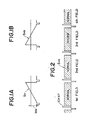
- a video signal S v shown in Fig. 1A is inverted in its polarity about the turn-up level V m which is set between the white and black levels to form a scrambled video signal S vs ' shown in Fig. 1B.
- V m which is set between the white and black levels to form a scrambled video signal S vs ' shown in Fig. 1B.
- a scramble pattern is formed in an arbitrary arrangement of level-inverted and non-inverted filed periods, as shown in Fig.2 and is transmitted repeatedly.
- an identification signal ID which indicates that the broadcasting program is scrambled
- a key code signal KY which is used for descrambling the scramble pattern, are inserted at predetermined positions ID+KY of Fig. 2 of a vertical blanking interval, respectively.
- the identification signal ID having a constant level is inserted in the sixteenth horizontal scanning period of the vertical blanking interval, and the key code signal KY is inserted in the seventeenth and eighteenth horizontal scanning periods of the vertical blanking interval.
- the level-inverted field period is detected based on the key code signal KY, and then unscrambling must be performed by reinverting the signal during this period to obtain the original video signal.
- the turn-up level for reinversion is formed at the receiver corresponding to the turn-up level V at the transmitter. If the turn-up level at the receiver was subjected to the influence of variations in the electronic components having ambient temperature fluctuations, for example, the reinversion would not result in the reproduction of the original waveform.
- the signal S which is inverted about the turn-up level V m at the transitier is reinverted about the identical level V m at the receiver, the waveform equal to the original one of the signal S v shown in Fig.
- the level of the identification signal ID set at the identification level related to the turn-up level V m is transmitted.
- the turn-up level based on the level of the signal V m ' and used for reinversion provides accurate unscrambling because the level of the identification signal ID varies with the video signal. Thus, no special adjustment need be performed at the receiver side.
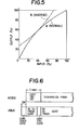
- Fig. 5 shows the input/output characteristics of the VTR.
- a curve A indicates signal characteristics of the normal portion (Fig. 2) of the signal
- a curve B indicates the signal characteristics of the signal portion inverted with respect to a 50% inverse level (half-way between the black level and the white level).
- the signal characteristics of the normal field are different from those of the inverted field.
- the distortion in the reinverted signal becomes different from that of the normal portion of the signal.
- the reproduced pictures flicker at the time that the normal portion is inverted or the inverted portion is reinverted when the scrambled signal S vs in Fig. 2 is unscrambled.
- a turn-up level control circuit must be used in the receiver system described above.
- a viewer or a person who installs a descrambler must adjust the descrambler.
- the person who installs the unscrambler performs the adjustment of the unscrambler, the installation cost is increased.
- readjustment of the unscrambler is required.
- the adjustment requires skill. As a result, fine adjustment cannot be performed, and the viewer watches the screen pictures with degraded quality.
- apparatus for unscrambling transmitted scrambled television signals including a scrambled video signal having a first scrambling pattern, a scrambled control signal having a second scrambling pattern, and unscrambling signals, the apparatus comprising:
- a screen control signal SR is sent from the broadcast station for one minute, and a scrambled program follows the screen control signal SR.
- a control start code is sent prior to 10 V (where V is the field) before the signal SR is sent.
- I D , KY and program codes follow the control start code.
- a control end code is inserted in the midst of the KY, ID and program codes of the vertical blanking period at the end of the signal SR.
- the audio signals can be scrambled by using the scrambling pattern in accordance with any technique in the audio channel. Any one of the above-described codes is obtained such that a binary signal having a predetermined number of bits is NRZ-modulated.
- the key code KY is a deciphering key code for unscrambling the scrambled video signal and has a code for designating the scrambling pattern.
- the screen control signal SR is used to display the control pattern for one minute before the program is displayed.
- the control start signal may be detected to start the VTR or the unscrambler.
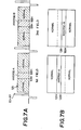
- the screen control signal SR is scrambled as shown in Fig. 7A, and is displayed on the screen as shown in Fig. 7B if it is not unscrambled.
- the screen control signal SR forms an inverse-A at substantially the center of the screen in the range of 101H to 130H and an inverse-B in the range of 131H to 160H.
- the inverse-A and inverse-B are alternately formed in every field. In this manner, the screen control signal SR has a scrambling pattern different from that of the program.
- the inverse-A and inverse-B of the screen control signal SR are reinverted by the descrambler.
- the reinverted components are directly applied to the CRT, the picture flickers. Therefore, the inverse level for reinversion must be controlled to minimize flicker.
- This control is performed by means of a control knob operated by the viewer. This control operation can be easily performed by any viewer.
- the contents of the inverse-A and inverse-B may comprise monochrome video components. In such case, flicker is emphasized at the horizontal scanning lines 101H, 130H, 131H and 160H, so that the viewer can easily control the picture to minimize flicker.
- Fig. 8 is a schematic block diagram showing a sending-side apparatus for producing television signals of Fig. 6.
- a video signal S of a specific program is supplied to an input terminal 1.
- the video signal S is then supplied to a scrambler 2 and a sync separator 3, and horizontal and vertical sync pulses HD and VD are separated from the video signal S.
- a scramble pattern generator 4 generates a predetermined scrambling pattern signal S 1 in response to the horizontal and vertical sync pulses HD and VD.
- the scrambler 2 inverts a predetermined field period of the video signal S v in accordance with the predetermined scrambling pattern signal S 1 .
- a screen control scramble pattern generator 5 generates a screen control scrambling pattern signal S 2 shown in Fig. 7A so as to scramble the signal for one minute prior to the program.
- the signals S 1 and S 2 are digitally coded as key codes by encoders 6 and 7, respectively. Therefore, the key codes include a key code for deciphering the signal SR and a key code for deciphering the scrambled program. These key codes and'the various codes such as a program code formed by a code generator 8 are inserted by an adder 9 in a predetermined period of a scrambled signal S v '. The signal with the various codes inserted therein appears as a scrambled television signal S vs at an output terminal 10.
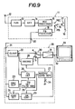
- Fig. 9 schematically illustrates a video signal receiving apparatus which includes a unscrambling circuit 35, a VTR 11 and a monitor 33.
- the VTR 11 receives a broadcasting signal from an antenna 12.
- the received signal is provided to a tuner 13 in order to select a scrambled television signal and the signal selected by the tuner 13 is provided to a detector 14.
- the detector 14 supplies the signal to a recording processor 15 which, in the conventional manner, frequency modulates a Y signal and converts chrominance signals to a lower frequency.
- the signal from the recording processor 15 is supplied to a record terminal REC of a switch 16.
- the switch 16 provides a circuit path through the terminal REC, the received signal is supplied to a magnetic head 17 for recording on a magnetic tape 18.
- the reproduction signal is supplied to a playback processor 19 which demodulates the Y signal and converts the chrominance signals to the original higher frequency through a playback terminal PB of the switch 16. Then, the Y signal and the chrominance signals are synthesized to provide a composite video signal.
- the reproduced signal is supplied to a video output terminal 20.
- the unscrambling circuit 35 has an input terminal 21 that accepts the composite signal.
- the composite signal is supplied to a clamping circuit 22, and the pedestal level of the composite signal is clamped therein.
- Horizontal and vertical synchronizing pulses in the composite signal are separated by a sync separating circuit 23.
- a code detector 24 detects the key code signal based on the horizontal and vertical synchronizing pulses from the circuit 23.
- a detecting pulse generator 25 generates a detecting pulse for detecting a turn-up level V ' based on the horizontal and vertical synchronizing pulses in order to detect the identification signal ID inserted in the sixteenth horizontal scanning period.
- the clamped signal from the circuit 22 is supplied to a detecting circuit 26 for detecting the level V m '.
- the turn-up level V m ' of the signal is detected in the detecting circuit 26 in accordance with the detecting pulse from the generator 25.
- an inverse level generator 27 Based on the detected level V m ', an inverse level generator 27 provides an inverse level (or turn-up level) for unscrambling in accordance with the level V m '.
- an inverting circuit 28 inverts the level of the signal from the clamping circuit 22 in accordance with the inverse level.
- a switching control circuit 29 recovers the scrambling pattern in accordance with the detected key code signal and the detected level V m ', that is, the signal ID.
- the switching control circuit 29 detects a scrambling pattern consisting of the level-inverted period and the non-inverted period of the input composite signal. Then, the switching circuit 29 generates a unscrambling signal.
- a switch 30 is changed over to a contact b, and in the case of the non-inverted period, the switch 30 is at a contact a. Therefore, when the switch 30 is at the contact a, the composite signal is directly provided from the switch 30.
- the switch 30 when the switch 30 is at the contact b, the inverted, that is, the reinverted, original level signal is provided from the switch 30. Accordingly, a completely descrambled signal can be obtained.
- the completely descrambled signal is output from an output terminal 32 through a buffer amplifier 31. Therefore, the output signal at the output terminal 32 is supplied to the monitor 33 in order to view a correct image.
- the screen control pattern unscrambled from that shown in F ig. 7B is displayed on the screen of the monitor 33 for one minute.
- the viewer controls an inverse level control variable resistor 34 in the inverse level generator 27 to minimize flicker. Therefore, the difference between the characteristic curves A and B of Fi g . 5 is minimized, as shown in Fig. 10.
- the scrambled program is unscrambled in accordance with this inverse level. As a result, flicker of the playback picture can be minimized.
- the signal SR is followed by the program. However, the signal SR may be inserted in or after the program.
Landscapes
- Engineering & Computer Science (AREA)
- Multimedia (AREA)
- Signal Processing (AREA)
- Computer Security & Cryptography (AREA)
- Two-Way Televisions, Distribution Of Moving Picture Or The Like (AREA)
- Television Signal Processing For Recording (AREA)
Applications Claiming Priority (2)
| Application Number | Priority Date | Filing Date | Title |
|---|---|---|---|
| JP123614/83 | 1983-07-07 | ||
| JP58123614A JPS6016082A (ja) | 1983-07-07 | 1983-07-07 | スクランブルテレビジヨン信号の伝送方式 |
Publications (3)
| Publication Number | Publication Date |
|---|---|
| EP0134656A2 true EP0134656A2 (de) | 1985-03-20 |
| EP0134656A3 EP0134656A3 (en) | 1986-03-19 |
| EP0134656B1 EP0134656B1 (de) | 1989-11-23 |
Family
ID=14864951
Family Applications (1)
| Application Number | Title | Priority Date | Filing Date |
|---|---|---|---|
| EP84304655A Expired EP0134656B1 (de) | 1983-07-07 | 1984-07-06 | Vorrichtung zur Entschleierung geschützter Fernsehbilder |
Country Status (7)
| Country | Link |
|---|---|
| US (1) | US4635113A (de) |
| EP (1) | EP0134656B1 (de) |
| JP (1) | JPS6016082A (de) |
| AU (1) | AU572521B2 (de) |
| BR (1) | BR8403390A (de) |
| CA (1) | CA1226060A (de) |
| DE (1) | DE3480583D1 (de) |
Cited By (3)
| Publication number | Priority date | Publication date | Assignee | Title |
|---|---|---|---|---|
| GB2191664A (en) * | 1986-06-16 | 1987-12-16 | Gen Instrument Corp | A cable tv converter for preventing unauthorized programme viewing |
| FR2684832A1 (fr) * | 1991-10-02 | 1993-06-11 | Reolid Lopez Ricardo | Systeme de codage simultane de divers signaux de television et de decodage de ceux-ci en radio-frequence. |
| CZ301694B6 (cs) * | 1998-05-07 | 2010-05-26 | Nagravision S.A. | Mechanismus shody mezi prijímacem a bezpecnostním modulem |
Families Citing this family (13)
| Publication number | Priority date | Publication date | Assignee | Title |
|---|---|---|---|---|
| GB2183378A (en) * | 1985-11-25 | 1987-06-03 | Philips Electronic Associated | Receiving scrambled signals |
| FR2655802B1 (fr) * | 1989-12-08 | 1992-01-24 | Europ Rech Electr Lab | Procede de promotion d'emissions de television a peage et dispositif de mise en óoeuvre. |
| EP0619677A3 (de) * | 1993-04-09 | 1995-03-08 | Matsushita Electric Industrial Co Ltd | System zur Verschlüsselung eines digitalen Videosignals. |
| US6021307A (en) | 1994-04-07 | 2000-02-01 | Chan; Hark C. | Information distribution and processing system |
| US7991347B1 (en) | 1994-04-07 | 2011-08-02 | Data Innovation Llc | System and method for accessing set of digital data at a remote site |
| US6473860B1 (en) | 1994-04-07 | 2002-10-29 | Hark C. Chan | Information distribution and processing system |
| US6188869B1 (en) | 1994-04-07 | 2001-02-13 | Hark C. Chan | Information distribution and processing system |
| US5502767A (en) * | 1994-05-27 | 1996-03-26 | Sasuta; Michael | Method for maintaining secure information synchronization on a control channel |
| US6314574B1 (en) | 1994-06-08 | 2001-11-06 | Hark Chan | Information distribution system |
| US6289200B1 (en) | 1994-07-25 | 2001-09-11 | Hark C. Chan | Information distribution system which intermittaly transmits radio frequency signal digital data |
| US7181758B1 (en) | 1994-07-25 | 2007-02-20 | Data Innovation, L.L.C. | Information distribution and processing system |
| JPH08107389A (ja) * | 1994-10-04 | 1996-04-23 | Hitachi Ltd | 映像情報課金システム |
| WO2000052690A1 (en) * | 1999-02-26 | 2000-09-08 | Hitachi, Ltd. | Digital signal recorder, reproducer and recording medium |
Family Cites Families (6)
| Publication number | Priority date | Publication date | Assignee | Title |
|---|---|---|---|---|
| GB841627A (en) * | 1956-12-20 | 1960-07-20 | Rank Organisation Ltd | Improvements in or relating to television systems |
| US3924059A (en) * | 1972-02-18 | 1975-12-02 | Teleglobe Pay Tv System Inc | Pay television systems |
| US4024576A (en) * | 1973-08-15 | 1977-05-17 | System Development Corporation | Method and apparatus for scrambling and unscrambling communication signals |
| AU562395B2 (en) * | 1981-09-10 | 1987-06-11 | Sony Corporation | Subscription television system |
| US4454543A (en) * | 1981-11-06 | 1984-06-12 | Oak Industries Inc. | Dynamic video scrambling |
| CA1213972A (en) * | 1983-07-13 | 1986-11-12 | Takashi Okada | Apparatus for scrambling a television signal |
-
1983
- 1983-07-07 JP JP58123614A patent/JPS6016082A/ja active Pending
-
1984
- 1984-06-28 CA CA000457669A patent/CA1226060A/en not_active Expired
- 1984-06-29 US US06/626,155 patent/US4635113A/en not_active Expired - Fee Related
- 1984-07-04 AU AU30263/84A patent/AU572521B2/en not_active Ceased
- 1984-07-06 EP EP84304655A patent/EP0134656B1/de not_active Expired
- 1984-07-06 DE DE8484304655T patent/DE3480583D1/de not_active Expired
- 1984-07-06 BR BR8403390A patent/BR8403390A/pt not_active IP Right Cessation
Cited By (5)
| Publication number | Priority date | Publication date | Assignee | Title |
|---|---|---|---|---|
| GB2191664A (en) * | 1986-06-16 | 1987-12-16 | Gen Instrument Corp | A cable tv converter for preventing unauthorized programme viewing |
| GB2191664B (en) * | 1986-06-16 | 1989-12-13 | Gen Instrument Corp | Security arrangement for downloadable cable television converters |
| FR2684832A1 (fr) * | 1991-10-02 | 1993-06-11 | Reolid Lopez Ricardo | Systeme de codage simultane de divers signaux de television et de decodage de ceux-ci en radio-frequence. |
| ES2038913A2 (es) * | 1991-10-02 | 1993-08-01 | Teleco Proyects S L | Sistema de codificacion simultanea de varias senales de television y decodificacion de las mismas en radiofrecuencia. |
| CZ301694B6 (cs) * | 1998-05-07 | 2010-05-26 | Nagravision S.A. | Mechanismus shody mezi prijímacem a bezpecnostním modulem |
Also Published As
| Publication number | Publication date |
|---|---|
| DE3480583D1 (en) | 1989-12-28 |
| EP0134656A3 (en) | 1986-03-19 |
| BR8403390A (pt) | 1985-06-18 |
| AU3026384A (en) | 1985-01-10 |
| AU572521B2 (en) | 1988-05-12 |
| CA1226060A (en) | 1987-08-25 |
| EP0134656B1 (de) | 1989-11-23 |
| US4635113A (en) | 1987-01-06 |
| JPS6016082A (ja) | 1985-01-26 |
Similar Documents
| Publication | Publication Date | Title |
|---|---|---|
| US4533949A (en) | Subscription television system | |
| EP0134656B1 (de) | Vorrichtung zur Entschleierung geschützter Fernsehbilder | |
| US5539823A (en) | Subscription television picture scrambling and descrambling system providing compatibility with different such systems | |
| CA1219060A (en) | Method and apparatus for recording scrambled television signals | |
| US4458268A (en) | Sync displacement scrambling | |
| EP0128770B1 (de) | Videochiffrierungssystem | |
| US4467353A (en) | Television signal scrambling system and method | |
| EP0449633A1 (de) | Fernsehen mit Bezahlung | |
| US4700388A (en) | Apparatus for scrambling a television signal | |
| US4628359A (en) | Memory selecting system for scrambled television receiver | |
| US3440338A (en) | Subscription television system | |
| EP0592233B1 (de) | Verschlüsselungssystem zur Verhinderung illegaler Benutzung | |
| JPH027236B2 (de) | ||
| CA1233232A (en) | Television signal transmission system | |
| US4636855A (en) | Scrambled television signal receiver system | |
| EP1052852B1 (de) | Bildsignalausgabegerät und Bildsignaleingabegerät | |
| JPH0462237B2 (de) | ||
| US5272751A (en) | Pay television | |
| US6028941A (en) | Method for the defeat of illegal descramblers sensitive to the edges of sync in scrambled video | |
| US6477253B1 (en) | Method and apparatus for television signal scrambling using vertical sync replacement | |
| JPS5941988A (ja) | テレビジヨン信号のスクランブル方式 | |
| JPH057918B2 (de) | ||
| JPH06253307A (ja) | テレビジョン信号のスクランブル方法及び装置 | |
| JPH03147490A (ja) | 有料放送送受信装置 | |
| JPH0580195B2 (de) |
Legal Events
| Date | Code | Title | Description |
|---|---|---|---|
| PUAI | Public reference made under article 153(3) epc to a published international application that has entered the european phase |
Free format text: ORIGINAL CODE: 0009012 |
|
| 17P | Request for examination filed |
Effective date: 19840712 |
|
| AK | Designated contracting states |
Designated state(s): DE FR GB NL |
|
| PUAL | Search report despatched |
Free format text: ORIGINAL CODE: 0009013 |
|
| AK | Designated contracting states |
Kind code of ref document: A3 Designated state(s): DE FR GB NL |
|
| 17Q | First examination report despatched |
Effective date: 19880302 |
|
| GRAA | (expected) grant |
Free format text: ORIGINAL CODE: 0009210 |
|
| AK | Designated contracting states |
Kind code of ref document: B1 Designated state(s): DE FR GB NL |
|
| ET | Fr: translation filed | ||
| REF | Corresponds to: |
Ref document number: 3480583 Country of ref document: DE Date of ref document: 19891228 |
|
| PLBE | No opposition filed within time limit |
Free format text: ORIGINAL CODE: 0009261 |
|
| STAA | Information on the status of an ep patent application or granted ep patent |
Free format text: STATUS: NO OPPOSITION FILED WITHIN TIME LIMIT |
|
| 26N | No opposition filed | ||
| PGFP | Annual fee paid to national office [announced via postgrant information from national office to epo] |
Ref country code: GB Payment date: 19940628 Year of fee payment: 11 |
|
| PGFP | Annual fee paid to national office [announced via postgrant information from national office to epo] |
Ref country code: DE Payment date: 19940708 Year of fee payment: 11 |
|
| PGFP | Annual fee paid to national office [announced via postgrant information from national office to epo] |
Ref country code: FR Payment date: 19940711 Year of fee payment: 11 |
|
| PGFP | Annual fee paid to national office [announced via postgrant information from national office to epo] |
Ref country code: NL Payment date: 19940731 Year of fee payment: 11 |
|
| PG25 | Lapsed in a contracting state [announced via postgrant information from national office to epo] |
Ref country code: GB Effective date: 19950706 |
|
| PG25 | Lapsed in a contracting state [announced via postgrant information from national office to epo] |
Ref country code: NL Effective date: 19960201 |
|
| GBPC | Gb: european patent ceased through non-payment of renewal fee |
Effective date: 19950706 |
|
| NLV4 | Nl: lapsed or anulled due to non-payment of the annual fee |
Effective date: 19960201 |
|
| PG25 | Lapsed in a contracting state [announced via postgrant information from national office to epo] |
Ref country code: DE Effective date: 19960402 |
|
| PG25 | Lapsed in a contracting state [announced via postgrant information from national office to epo] |
Ref country code: FR Effective date: 19960430 |
|
| REG | Reference to a national code |
Ref country code: FR Ref legal event code: ST |
|
| REG | Reference to a national code |
Ref country code: FR Ref legal event code: ST |
|
| REG | Reference to a national code |
Ref country code: FR Ref legal event code: ST |