EP0134652A2 - Einrichtung zum Abheben und Wenden des Gehäusedeckels der hydraulischen Hubvorrichtung eines Schleppers - Google Patents
Einrichtung zum Abheben und Wenden des Gehäusedeckels der hydraulischen Hubvorrichtung eines Schleppers Download PDFInfo
- Publication number
- EP0134652A2 EP0134652A2 EP84304598A EP84304598A EP0134652A2 EP 0134652 A2 EP0134652 A2 EP 0134652A2 EP 84304598 A EP84304598 A EP 84304598A EP 84304598 A EP84304598 A EP 84304598A EP 0134652 A2 EP0134652 A2 EP 0134652A2
- Authority
- EP
- European Patent Office
- Prior art keywords
- cover
- tractor
- housing
- hoist
- lift mechanism
- Prior art date
- Legal status (The legal status is an assumption and is not a legal conclusion. Google has not performed a legal analysis and makes no representation as to the accuracy of the status listed.)
- Withdrawn
Links
Images


Classifications
-
- B—PERFORMING OPERATIONS; TRANSPORTING
- B66—HOISTING; LIFTING; HAULING
- B66F—HOISTING, LIFTING, HAULING OR PUSHING, NOT OTHERWISE PROVIDED FOR, e.g. DEVICES WHICH APPLY A LIFTING OR PUSHING FORCE DIRECTLY TO THE SURFACE OF A LOAD
- B66F19/00—Hoisting, lifting, hauling or pushing, not otherwise provided for
Definitions
- the Invention relates to apparatus for extracting the cover from the housing of a hydraulic lift mechanism of a tractor and then for inverting the cover.
- the hydraulic lift-mechanism may be, for example, the conventional three-point lift mechanism of an agricultural tractor.
- the housing cover of the hydraulic lift mechanism of a tractor is often heavy and is tightly and sealingly fitted into an opening in the top of the housing. Therefore a considerable upward force is usually required to extract and to raise the cover.
- the housing and the cover are often positioned beneath the cab of a tractor with little clearance between the cover and the cab. Therefore in many makes of tractor it is necessary first to remove or to dismantle parts of the cab before the cover can be removed and inverted. It is usually necessary to support the cover in an inverted position in order to gain access to control linkages and other parts of the lift mechanism which are commonly located in the cover.
- An object of the invention is to provide apparatus whereby the cover of the lift mechanism can be raised and then withdrawn from beneath the cab and inverted without necessarily removing or dismantling parts of the cab or with only minimal dismantling thereof or with only limited movement of the cab or both.
- apparatus for extracting the cover from the housing of a hydraulic lift mechanism of a tractor and then for inverting the cover and supporting it in an inverted position in which the cover is spaced from the housing comprises a pivotable structure arranged to be removably mounted on the tractor adjacent said housing; hoist means supported by the pivotable structure and operable to lift the cover from the housing and to raise the cover to an upper part of the structure; means for securing the cover in its raised position to the structure ; means for swinging the structure together with the cover from an initial position in which the cover is supported upright above the housing to a second position in which the cover is withdrawn from a position immediately above the housing and the cover is then swung to a final position in which the cover is supported inverted and spaced laterally from said initial position.
- the structure may comprise a plurality of rigid links arranged to be removably and pivotally attached to the tractor or a part of the lift mechanism thereof and supporting a fixed part of the hoist means.
- the hoist means may be a hoist comprising a body and a lifting element arranged to be lowered to engage the cover and then to be raised to lift the cover from the housing and to raise the cover to a position in which it can be secured to the body of the hoist.
- the hoist may be manually-operable to raise and to lower the lifting element or it may be of a power-operable kind.
- the structure conveniently includes stay means operable to limit the swinging of the structure into said second position, whereby the cover is supported in said final position.
- the stay means may comprise a pivotally-mounted arm with which a stop pin on another part of the structure or on a part of the lift mechanism of the tractor or on the tractor itself is engageable when the structure has been swung to said second position.
- the arm may for example have a longitudinal slot therein in which said stop pin is slidable freely to and from an end of the slot which is engaged by the stop pin when the structure has been swung into said second position.
- the stop piri' may be carried by a control beam of a three-point linkage of the lift mechanism of the tractor.
- the apparatus is shown mounted on a tractor adjacent the hydraulic lift housing cover which is to be removed, inverted and supported in an inverted position.
- the housing of the hydraulic lift mechanism which is fitted with the cover is indicated at 2A.
- the tractor is of the type having a cab of which part projects above the housing 2A and the cover 2.
- a rear wheel of the tractor is shown at 1.
- the housing 2A of the hydraulic lift mechanism is positioned between the rear wheels 1 and is fitted with the cover 2.
- Part of the cab of the tractor is indicated at 3.
- the cover 2 When it is necessary to carry out work on the hydraulic lift mechanism, the cover 2 must be removed and then be supported in an inverted position to enable the underneath and interior of the cover 2 to be exposed so that work can be performed on controls and other parts of the lift mechanism which are usually contained in the cover.
- the apparatus comprises a pivotable structure comprising a pair of laterally-spaced links 4 which are each connected at one end thereof for pivoting about a common axis 5 to fixed lugs on the tractor.
- the upper end 6 (as shown in Figure 5) of each of the links 4 is pivotally connected about a common axis 7 to a bridge 8 which carries a hoist 9.
- the bridge 8 is also connected for pivoting about the common axis 7 to a pair of cranked links 10 which are pivotally connected at their other ends at 11 to one end of the control beam 12 of the top link of a three-point linkage of the tractor or to some other part of the tractor spaced from the axis 5.
- Transverse handles
- Another pivotally-mounted stay arm 14 is pivotally attached at one end thereof to swing about the axis 5.
- the arm 14 has a slot 15 therein in which a stop pin 17 on the beam 12 of the three-point linkage is captive and is slidable along the slot 15 to a limiting end 16 thereof.
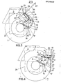
- the hoist 9 has a lifting chain or cable 18 carrying at its lower end a lifting plate 19 which is to be bolted to the top of the cover 2, as indicated at 20 in Figure 1.
- the lifting plate 19 has an upstanding lug 21 having a hole therein by which the lug 21 when raised is secured to a fixed part of the hoist 9 by a pin 22 engaged in the hole.
- the hoist may be of any kind having a lifting chain or cable 18.
- it may be of the kind having pulleys 23 around which the cable 18 is passed, the pulleys 23 being moved by means of a pair of lead screws 24 and 25.
- the lead screws 24 and 25 have oppositely-handed screw- threads, whereby double travel of the pulleys 23 is effected per revolution of the outer lead screw 25.
- the lead screw 25 is turned by means of a key, not shown.
- the service tool is used as follows:
- the lever 26 When the service tool has reached the position shown in Figure 3, the lever 26 is secured to the hoist 9 by inserting the lever 26 in a socket 28 in a fixed part of the hoist 9, as indicated in Figure 3.
- the hoist 9 together with the cover 2 is swung about the pivot 7 into the final position shown in Figure 4 in which the cover 2 is supported in an inverted position in which it is spaced laterally from the position shown in Figure 1. This enables work to be performed on the cover and also supports the cover to enable work to be performed on the exposed lift mechanism parts within the housing.
- the cover 2 and the service tool are returned in the reverse direction from the position in Figure 4, through the position in Figure 3, to the position shown in Figure 2.
- the lifting plate 19 is detached from the body 9 of the hoist and the cover 2 is lowered into position on the housing 2A. Then the lifting plate 19 is detached from the cover 2 and the whole service tool is removed from the tractor.
- Arms 4 and 10 of different lengths and shapes and having different mounting positions may be used to enable the service tool to be used on different makes of tractor.
Landscapes
- Life Sciences & Earth Sciences (AREA)
- Engineering & Computer Science (AREA)
- Geology (AREA)
- Mechanical Engineering (AREA)
- Structural Engineering (AREA)
- Lifting Devices For Agricultural Implements (AREA)
Applications Claiming Priority (2)
| Application Number | Priority Date | Filing Date | Title |
|---|---|---|---|
| GB8318611 | 1983-07-08 | ||
| GB838318611A GB8318611D0 (en) | 1983-07-08 | 1983-07-08 | Apparatus for extracting and inverting cover of hydraulic lift mechanism |
Publications (2)
| Publication Number | Publication Date |
|---|---|
| EP0134652A2 true EP0134652A2 (de) | 1985-03-20 |
| EP0134652A3 EP0134652A3 (de) | 1986-12-30 |
Family
ID=10545476
Family Applications (1)
| Application Number | Title | Priority Date | Filing Date |
|---|---|---|---|
| EP84304598A Withdrawn EP0134652A3 (de) | 1983-07-08 | 1984-07-05 | Einrichtung zum Abheben und Wenden des Gehäusedeckels der hydraulischen Hubvorrichtung eines Schleppers |
Country Status (2)
| Country | Link |
|---|---|
| EP (1) | EP0134652A3 (de) |
| GB (1) | GB8318611D0 (de) |
Family Cites Families (5)
| Publication number | Priority date | Publication date | Assignee | Title |
|---|---|---|---|---|
| US2836883A (en) * | 1956-09-24 | 1958-06-03 | Willis H Puck | Device for removing parts from a tractor |
| DE1852933U (de) * | 1962-03-26 | 1962-06-07 | Matra Werke Gmbh | Hebezeug fuer die brennkraftmaschine eines kraftfahrzeuges. |
| US3262590A (en) * | 1964-07-28 | 1966-07-26 | Harry A Downard | Lifting device for plumbing fixtures |
| US4030705A (en) * | 1976-01-19 | 1977-06-21 | Jacob Bontrager | Vehicle supported motor lift |
| US4181290A (en) * | 1978-12-15 | 1980-01-01 | Affolter Bill G | Manhole cover lifting device |
-
1983
- 1983-07-08 GB GB838318611A patent/GB8318611D0/en active Pending
-
1984
- 1984-07-05 EP EP84304598A patent/EP0134652A3/de not_active Withdrawn
Also Published As
| Publication number | Publication date |
|---|---|
| GB8318611D0 (en) | 1983-08-10 |
| EP0134652A3 (de) | 1986-12-30 |
Similar Documents
| Publication | Publication Date | Title |
|---|---|---|
| US5501257A (en) | Tree trimming apparatus | |
| CA1276006C (en) | Apparatus for operating manhole cover | |
| EP0116597A1 (de) | Radhebeandordnung | |
| DE239522T1 (de) | Schneeschleuder mit pendelnden raedern. | |
| US5464314A (en) | Device for handling a vehicle wheel | |
| EP0134652A2 (de) | Einrichtung zum Abheben und Wenden des Gehäusedeckels der hydraulischen Hubvorrichtung eines Schleppers | |
| JPS60259104A (ja) | 農用トラクタと作業機の連結装置 | |
| JPS61108074A (ja) | トラクタの油圧リフト機構のハウジングカバ−をはずして反転させる装置 | |
| CN212727570U (zh) | 一种线路板加工用定位装置 | |
| US4304520A (en) | Compound boom latch | |
| US4436162A (en) | Implement attachment for the front end of a tractor | |
| US4217997A (en) | Arrangement at a continuous casting plant | |
| KR100226369B1 (ko) | 배기카트 | |
| EP1088474A3 (de) | Pflug mit Hubvorrichtung | |
| JPH0340091Y2 (de) | ||
| JPS6145246Y2 (de) | ||
| JP2509321Y2 (ja) | トラクタ用リフトダンプアタッチメント | |
| JPH0447228Y2 (de) | ||
| JPH11253003A (ja) | ロータリー耕耘装置のリヤカバー | |
| JPH0531338Y2 (de) | ||
| JP3233337B2 (ja) | ドラム缶処理方法とドラム缶処理装置 | |
| JPS5933212Y2 (ja) | トラクタの作業機装着装置 | |
| JPS621853Y2 (de) | ||
| JP3457567B2 (ja) | 農作業機用スタンド装置 | |
| JPS56105142A (en) | Front-fitted 3-points link apparatus |
Legal Events
| Date | Code | Title | Description |
|---|---|---|---|
| PUAI | Public reference made under article 153(3) epc to a published international application that has entered the european phase |
Free format text: ORIGINAL CODE: 0009012 |
|
| AK | Designated contracting states |
Designated state(s): AT BE CH DE FR GB IT LI NL SE |
|
| PUAL | Search report despatched |
Free format text: ORIGINAL CODE: 0009013 |
|
| AK | Designated contracting states |
Kind code of ref document: A3 Designated state(s): AT BE CH DE FR GB IT LI NL SE |
|
| STAA | Information on the status of an ep patent application or granted ep patent |
Free format text: STATUS: THE APPLICATION IS DEEMED TO BE WITHDRAWN |
|
| 18D | Application deemed to be withdrawn |
Effective date: 19870701 |