EP0134366B1 - Verfahren und Anlage zur Bearbeitung von Rohlingen aus einer Blechwalzstrasse - Google Patents
Verfahren und Anlage zur Bearbeitung von Rohlingen aus einer Blechwalzstrasse Download PDFInfo
- Publication number
- EP0134366B1 EP0134366B1 EP83401623A EP83401623A EP0134366B1 EP 0134366 B1 EP0134366 B1 EP 0134366B1 EP 83401623 A EP83401623 A EP 83401623A EP 83401623 A EP83401623 A EP 83401623A EP 0134366 B1 EP0134366 B1 EP 0134366B1
- Authority
- EP
- European Patent Office
- Prior art keywords
- mother sheet
- length
- sheets
- sheet
- mother
- Prior art date
- Legal status (The legal status is an assumption and is not a legal conclusion. Google has not performed a legal analysis and makes no representation as to the accuracy of the status listed.)
- Expired
Links
- 238000000034 method Methods 0.000 title claims abstract description 26
- 238000005096 rolling process Methods 0.000 title claims abstract description 11
- 238000009434 installation Methods 0.000 title claims description 31
- 230000008569 process Effects 0.000 title claims description 7
- 238000003754 machining Methods 0.000 title 1
- 238000005520 cutting process Methods 0.000 claims abstract description 20
- 230000007547 defect Effects 0.000 claims description 13
- 238000004364 calculation method Methods 0.000 claims description 10
- 230000007246 mechanism Effects 0.000 claims description 9
- 238000005259 measurement Methods 0.000 claims description 3
- 230000003287 optical effect Effects 0.000 claims description 3
- 238000005457 optimization Methods 0.000 claims description 2
- 238000012545 processing Methods 0.000 claims description 2
- 230000005540 biological transmission Effects 0.000 claims 1
- 230000001419 dependent effect Effects 0.000 claims 1
- 238000001514 detection method Methods 0.000 claims 1
- 238000010408 sweeping Methods 0.000 claims 1
- 238000009826 distribution Methods 0.000 description 12
- 238000009966 trimming Methods 0.000 description 6
- 238000010586 diagram Methods 0.000 description 4
- 230000006870 function Effects 0.000 description 4
- 239000002184 metal Substances 0.000 description 4
- 238000012937 correction Methods 0.000 description 3
- 238000005070 sampling Methods 0.000 description 3
- 239000003638 chemical reducing agent Substances 0.000 description 2
- 230000008878 coupling Effects 0.000 description 2
- 238000010168 coupling process Methods 0.000 description 2
- 238000005859 coupling reaction Methods 0.000 description 2
- 230000010365 information processing Effects 0.000 description 2
- 238000004519 manufacturing process Methods 0.000 description 2
- 239000000463 material Substances 0.000 description 2
- 239000000700 radioactive tracer Substances 0.000 description 2
- 238000013519 translation Methods 0.000 description 2
- 238000010200 validation analysis Methods 0.000 description 2
- 241000251556 Chordata Species 0.000 description 1
- 241001644893 Entandrophragma utile Species 0.000 description 1
- 238000009825 accumulation Methods 0.000 description 1
- 239000004020 conductor Substances 0.000 description 1
- 238000006073 displacement reaction Methods 0.000 description 1
- 238000011156 evaluation Methods 0.000 description 1
- 238000012986 modification Methods 0.000 description 1
- 230000004048 modification Effects 0.000 description 1
- 230000002093 peripheral effect Effects 0.000 description 1
- 230000009467 reduction Effects 0.000 description 1
- 238000010008 shearing Methods 0.000 description 1
- 238000012546 transfer Methods 0.000 description 1
- 238000011144 upstream manufacturing Methods 0.000 description 1
Images


Classifications
-
- B—PERFORMING OPERATIONS; TRANSPORTING
- B27—WORKING OR PRESERVING WOOD OR SIMILAR MATERIAL; NAILING OR STAPLING MACHINES IN GENERAL
- B27B—SAWS FOR WOOD OR SIMILAR MATERIAL; COMPONENTS OR ACCESSORIES THEREFOR
- B27B31/00—Arrangements for conveying, loading, turning, adjusting, or discharging the log or timber, specially designed for saw mills or sawing machines
- B27B31/06—Adjusting equipment, e.g. using optical projection
-
- B—PERFORMING OPERATIONS; TRANSPORTING
- B23—MACHINE TOOLS; METAL-WORKING NOT OTHERWISE PROVIDED FOR
- B23D—PLANING; SLOTTING; SHEARING; BROACHING; SAWING; FILING; SCRAPING; LIKE OPERATIONS FOR WORKING METAL BY REMOVING MATERIAL, NOT OTHERWISE PROVIDED FOR
- B23D15/00—Shearing machines or shearing devices cutting by blades which move parallel to themselves
- B23D15/06—Sheet shears
-
- B—PERFORMING OPERATIONS; TRANSPORTING
- B23—MACHINE TOOLS; METAL-WORKING NOT OTHERWISE PROVIDED FOR
- B23D—PLANING; SLOTTING; SHEARING; BROACHING; SAWING; FILING; SCRAPING; LIKE OPERATIONS FOR WORKING METAL BY REMOVING MATERIAL, NOT OTHERWISE PROVIDED FOR
- B23D33/00—Accessories for shearing machines or shearing devices
Definitions
- the present invention relates to the treatment of raw sheets (hereinafter called parent sheets) of great thickness and large dimensions leaving a rolling mill.
- the processing of products from a rolling mill train for flat products firstly involves determining “writability” in the raw sheet, then scaling them down using shears.
- the term “writability” here designates the distribution that can be made in a given parent sheet, of sheets to be cut (hereinafter called daughter sheets) according to a cutting process involving a minimum loss of metal taking into account the irregularities edges of the parent sheet on the one hand and defects in full sheet on the other.
- the determination of the writability is done mainly manually by chalk tracing and by approximate evaluation.
- the tracer moves on the sheet metal by identifying the usable area or areas, declares by approximate estimates the partial or total writability of the daughter sheets and proceeds to a determination of the remaining recoverable areas, if there is location. Once the tracing plan has been raised, it is transmitted to the shear and cut-to-length conductors.
- the object of the invention is therefore to provide a method and an installation for treating parent plates leaving a rolling mill which are completely free from the drawbacks set out above.
- the invention therefore firstly relates to a method for the treatment of parent plates from a rolling mill in order to cut these sheets into daughter plates of predetermined dimensions, during which the determination of the writability of each parent sheet to take up a tracing plan allowing optimal use of the latter, then each parent sheet is passed through dimensioning means for cutting into daughter sheets, characterized in that the operation determination of the writability consists in projecting onto the mother plate a network of crossed light lines, in selectively moving each of these light lines parallel to itself in order to delimit on the mother plate a batch of daughter plates to be obtained, recording the coordinates of the light lines with respect to a reference system assigned to the parent plate and cutting the parent plate as a function of the coordinates obtained.
- the tracing operation can be carried out by an operator located in an observation cabin, by an appropriate control of the light lines, which makes this work convenient and exact, the recorded coordinates being able to be easily transmitted to the shears. of dimensioning.
- the invention also relates to an installation for implementing the method defined above.
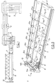
- Fig. 1 schematically represents a plan view of an installation according to the invention. It includes a tracing station 1 provided at its downstream end with a shearing machine 2 for trimming the head of the mother plates TM after which a marking unit 3 is provided. This unit is mounted above a transfer table 4 intended to arrange the sheets to be cut on the path of a double edge shears 5 which is followed by a cutting shears 6. This ensures the cutting into daughter plates of the parent sheet.
- An evacuation table 7 of daughter plates is provided at the end of installation.
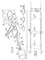
- the plotting station 1 a perspective view of which appears in FIG. 2 comprises a tracing table 8 known per se, the top of which is formed by a train of rollers 9 on which the mother plate TM can move from the rolling mill (not shown) from which it is obtained.
- a gantry 10 transversely spanning the path defined for the sheet.
- a ramp 12 of light sources 13a to 13g (seven in this case), while the gantry 10 supports two of these sources indicated by the references 14a and 14b.
- the light sources are preferably produced using lasers which can be masked using shutters when the beam they produce is not used.
- the light sources 14a and 14b each produce two parallel beams F1 and F2 located in the same plane and oriented downwards at different angles and are thus able to materialize on the mother sheet longitudinal light lines t 1 and t 2 . If lasers are used, the beams F1 and F2 can be obtained from beam lasers with cylindrical or scanning optics so that these beams strike the entire length of the sheet in a predetermined sequence.
- the light sources 13a to 13g each produce a light beam F3 so as to project on the sheet as many transverse lines ha to t 3 -g. These beams are preferably produced by lasers scanning in a variable plane.
- the sources 13a to 13g as a whole are mounted oscillating on supports (described below in detail) so that the lines which they produce can be placed at the option of the operator at a predetermined variable location in an area of the mother plate to which the laser in question is assigned.
- the lines t 3 -a to t 3 -g can move in the longitudinal direction at the option of the operator, by an appropriate control of the movements of the light sources 13a to 13g.
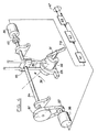
- Fig. 3 shows a diagram of a mechanism 15 for moving the light sources 14a and 14b.
- This mechanism comprises bearings 16 which are fixed on the gantry 10 and in which is mounted a ball screw 17.
- a support carriage 18 comprising nuts 19 is mounted movable in translation on the screw when the latter is rotated.
- This carriage supports one or the other of the light sources 14a or 14b provided here each with two lasers 20a and 20b respectively producing the beams F1 and F2.
- the screw 17 can be rotated by a stepping motor 21 by means of a coupling 22.
- An angular encoder 23 preferably of the absolute multi-turn type is also coupled to the screw 17. This encoder is capable to generate a binary code of the “Gray” type whose value is a function of the linear displacement of the carriage 18 along the screw 17. This code is converted into a pure binary code in a converter 24 followed by a correction circuit25 measurement tolerances and a calculation and control unit 26 which is connected to the stepping motor 21 and also to a computer 27 (FIG. 5) which will be described later.
- the mechanism 15 intended for the light source 14b further comprises a reducer 28, 29 due to the relatively large length of the worm 17 of this mechanism.
- This reducer is also coupled to an encoder 23 and shown in dotted lines in FIG. 3.
- Fig. 4 shows a control mechanism 30 for one of the light sources 13a to 13g. It includes a scanning laser 31 mounted on a support 32 oscillating around a horizontal axis, the optical axis of the laser being inclined relative to the horizontal, so that the beam F3 can draw a transverse line on the sheet- mother TM.
- the oscillating support is rotatably mounted in a fixed console 33.
- the mechanism further comprises a ball screw 34 on which is mounted movable in translation a nut 35 through which pass two smooth rods 36 fixed in the oscillating support 32.
- the screw 34 is coupled by a reduction gear 37 to a stepping motor 38 and to an angular encoder 39 by a coupling 40.
- the encoder 39 is connected to a converter 41 of Gray code into binary code followed by a circuit 42 of compensation for tolerances to which is connected a unit 43 of calculation and control which is connected to computer 27.
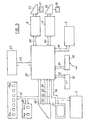
- Fig. 5 shows a general diagram of the information processing and control circuit designated by the reference 44.
- This circuit comprises as central component the microcomputer or computer 27 around which the following peripherals are grouped.
- a central computer 45 of very large capacity which may be the management computer of the company in which is installed the installation according to the invention.
- This computer stores and manages in particular the orders for the sheets to be delivered to customers and these orders are transferred by a line 46 to the computer 27 of the present installation in the form of a document called a "tracing ticket".
- This document which can be produced on a printer, includes in particular the dimensions and metallurgical characteristics of the sheets to be treated.
- the computer 27 is also connected by lines 47, 48 and 49 respectively to the light sources 13a to 13g and 14a, 14b, to a console 50 for tracing control, and to a monitor 51 or other display device by a line. 52, all these components being arranged in the tracing station 1.
- the information obtained during tracing is transferred to the management computer 45 and also by lines 53 and 54 to the shears 5 and 6 which are provided with control panels 55 and 56 and display screens 57 and 58. They are also sent as regards the abscissas noted during the tracing, to the marking unit 3 by a line 59, this unit being intended to affix on each sheet-daughter to be cut a complete identification label.
- the trimming shears 2 are connected to the computer 27 by the line 52.
- a device 60 for measuring the temperature is provided for making length corrections and thus compensate for the possible expansion of the sheets as a function of the temperature.
- This device is connected to the computer 27 by a line 61.
- Another device 62 connected to this computer by a line 63 makes it possible, if necessary, to take account of changes in thickness from one sheet to another, changes which can influence the measurements taken via the positions of the lasers during the tracing.
- the operator console 50 is also connected to the computer 27 by other lines 64, 65 and 66 on which pass orders relating to the defects observed on the parent plates during tracing, such as a curved sheet, an undersized sheet, a sheet with non-recoverable defects, etc.
- the installation that has just been described has the primary role of allowing an optimization of the distribution of the daughter plates in the parent plates, an operation which is essentially carried out in the tracing station 1 and which thus makes it possible to determine what specialists call "writability".
- the computer 27 having thus received the data concerning the positioning and the characteristics of the daughter plates to be traced, automatically controls the motor 21 and the light source 14b, which moves the light line t 2 to determine the location of the bank left of the sheet (seen in the direction of travel), this bank being called hereinafter "large bank”.
- the sheet progresses by being applied against the rule 11 by its opposite bank called hereinafter "small bank”.
- the longline line t 2 is placed at a theoretical dimension I max of this rule 11.
- the sheet being positioned so that its front edge or "head” is under the shears 2, it is trimmed and the operator controls the light source 14a to move the small edge line t i , this command being initiated on the console 50 and passing to the corresponding mechanism 15 (FIG. 3) via the computer 27.
- the lasers 14a and 14b are moved together by the same amplitude and in the same direction so that the lines t, and t 2 maintain the same spacing I max .
- the operator checks whether, in these conditions, the width writability is correct (no defect to the right of the line t 2 seen in the direction of advancement of the sheet). If it is correct, the writability in width is determined and the position of the line t 2 is validated by the operator and stored in the computer 27. Otherwise, the operator makes a correction and then validates the new position (operation 70), which gives rise to a useful width less than the maximum width (case which is not shown in FIG. 7).
- the parent sheet Due to the presence of the defect D in the opposite bank, the parent sheet has, in the example shown, a useful width l u actually smaller than the width I max , but this defect is eliminated in another way as we will see, the daughter plates ultimately cut therefore having the width I max , despite the presence of the defect.
- the writable data in useful width and in maximum width appear on the operator's screen 51 (operations 71 and 72).
- the installation is then ready to receive the data leading to the writability of the TM parent plate in length.
- the trimming shear 2 provides a reference for the length thereof after trimming the head of the sheet and / or cutting a sample.
- this length reference can also be obtained optically using one of the transverse lasers (13a to 13g). This laser will then be called "head laser”.
- the operator selects and positions one of the transverse lasers of the ramp 12, as a function of the theoretical length of the sheet (foot laser), so as to eliminate any irregularity at the opposite edge of the head and validates the position thus chosen.
- This operation then provides the computer 27 with a useful length value comprised between the blade of the shears 2 and the validated position of the foot laser, taking into account, where appropriate, the taking of the sample at the head of the sheet. Samples can optionally be delimited in other places thereof and the relative length data are extracted from the management computer 45 which via the computer 27 applies them to the lasers concerned of the ramp 12 .
- the position of the foot laser is then validated (operation 73).
- the computer 27 having received temperature data from the member 60 (FIG. 5), an interrogation is made if it is necessary to correct the value of the length recorded to compensate for the expansion. (Operations 73a.) The operator can then validate this length (74) or correct it (75).
- the computer 27 is now able to register in the mother plate TM a certain number of daughter plates (operation 76) taking into account, on the one hand, the tracing ticket which it received from the computer 45 and, on the other hand, dimensions taken by the shore lasers and the foot laser.
- the operator can (at 77) delimit the “dead bands” BM to isolate in the sheet the defect D (or another defect located elsewhere in the sheet) by an appropriate control of the lasers which are here the lasers 13d and 13th.
- the operator can also define an additional sample strip (at 78), after which the program goes to a tracing request operation at 79 which triggers the computer's calculation of the final tracing of the sheet according to all the data previously introduced.
- the computer positions all the lasers from the laser 13a to the foot laser; accordingly, the result is displayed on the screen 51 (operation 80).
- the program loops back to operation 80 so that a corrected tracing can be established.
- the program then proceeds to a marking validation operation 82, which blocks any modification in the tracing station 1, the tracing plane then being kept frozen until the sheet is evacuated.
- the computer 27 stores all the data in its memory (83).
- the treated parent plate in all cases allows distribution of daughter plates in accordance with the layout ticket and the orders defining the parameters of the daughter plates, taking account of the sheet metal's own tolerances -mother, temperature, sheet thickness, etc.
- the accumulation of tolerances does not make it possible to carry out the tracing with an optimal distribution and, in this case, the installation according to the invention makes it possible to find a distribution compromise leading nevertheless to an optimal use of the material of the parent plate while respecting the tolerances required for the product leaving the installation.
- the daughter plates are marketed with a nominal length c n which, barring exceptions, to be described below, must never be lowered.
- the sheets are delivered at this nominal dimension increased by a positive tolerance e, the practice requiring that the length of the product delivered has as much as possible the dimension c n + e called maximum length L max .
- this length may be insufficient taking into account the length of the sampling strip so that when cutting the daughter plates required by the tracing ticket all have a dimension c n + e.
- the computer 27 performs an average calculation affecting during tracing a length at daughter plates of value c n ⁇ c ⁇ c n + e. (Operation 84; fig. 6.)
- the computer is programmed so as to establish a distribution which eliminates one or more daughter plates, the fall from the parent plate then being recycled (operation 85).
- the daughter plates can be manufactured with a tolerance lying around the nominal value, for example in the case where these plates are used to manufacture tubes.
- the operator after determining the useful length L u of the parent plate at 76, the operator enters the limit values L m and L m of the range of tolerances allowed.
- the computer 27 is then configured so as to execute a distribution subroutine (operation 86) based on a calculation aimed at establishing the number x of sheets of length L M and the number y of length L m .
- E factor indicating the ratio of the sum of the lengths of the parent plates to the useful length of the parent plates.
- This algorithm therefore allows the computer 27 to determine the maximum number of daughter plates that can be traced in a parent plate considered.
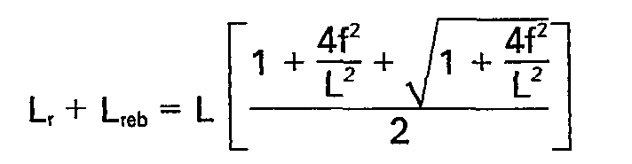
- the subroutine can include instructions implemented at the option of the operator leading to a tracing of daughter plates whose lengths are intermediate between L m and L m according to the formula: in which L, is the intermediate length of the daughter plates,
- the computer can also implement a distribution subroutine (operation 87) taking into account the faults existing in the parent plate and previously identified.
- the computer 27 considers each section of the mother sheet TM die provided defects as a sheet-mer length L u that is regarded as a new parent sheet in which the allocation may be established as described above.
- the subroutine includes instructions making it possible to group the bands which cannot be used in these "secondary" parent plates following the distribution calculation, with bands provided with defects, which leads to optimal use of material.
- the sheets are generally, always presented on the tracing table I so that their concave edge is turned towards the rule 11.
- the computer 27 can be controlled to transmit the corresponding data to the other members of the cutting installation and in particular to the marking machine 3, to the edge shears 5 and with the lengthening shears 6, the data can also be stored in the central management computer 45.
- the marking unit 3 receives the length data corresponding to the beginnings of the daughter plates and using these data affixes a mark on the daughter plates thus identified.
- shears 5 and 6 which can be ordered directly by the writability data recorded in the plotting station or else be ordered by an operator receiving this data and entering it on the control console. belonging to the shears.
- a cutting plane for the daughter plates is transmitted to the operator of the shears 6. It comprises the following instructions for positioning the movable stop of the shears necessary for obtaining the daughter plates.
Landscapes
- Engineering & Computer Science (AREA)
- Mechanical Engineering (AREA)
- Life Sciences & Earth Sciences (AREA)
- Wood Science & Technology (AREA)
- Forests & Forestry (AREA)
- Metal Rolling (AREA)
- Laser Beam Processing (AREA)
- Reduction Rolling/Reduction Stand/Operation Of Reduction Machine (AREA)
- Numerical Control (AREA)
Claims (26)


Priority Applications (3)
| Application Number | Priority Date | Filing Date | Title |
|---|---|---|---|
| DE8383401623T DE3368219D1 (en) | 1983-08-05 | 1983-08-05 | Process and installation for machining unfinished sheets issuing from a sheet rolling mill |
| EP83401623A EP0134366B1 (de) | 1983-08-05 | 1983-08-05 | Verfahren und Anlage zur Bearbeitung von Rohlingen aus einer Blechwalzstrasse |
| AT83401623T ATE24136T1 (de) | 1983-08-05 | 1983-08-05 | Verfahren und anlage zur bearbeitung von rohlingen aus einer blechwalzstrasse. |
Applications Claiming Priority (1)
| Application Number | Priority Date | Filing Date | Title |
|---|---|---|---|
| EP83401623A EP0134366B1 (de) | 1983-08-05 | 1983-08-05 | Verfahren und Anlage zur Bearbeitung von Rohlingen aus einer Blechwalzstrasse |
Publications (2)
| Publication Number | Publication Date |
|---|---|
| EP0134366A1 EP0134366A1 (de) | 1985-03-20 |
| EP0134366B1 true EP0134366B1 (de) | 1986-12-10 |
Family
ID=8191433
Family Applications (1)
| Application Number | Title | Priority Date | Filing Date |
|---|---|---|---|
| EP83401623A Expired EP0134366B1 (de) | 1983-08-05 | 1983-08-05 | Verfahren und Anlage zur Bearbeitung von Rohlingen aus einer Blechwalzstrasse |
Country Status (3)
| Country | Link |
|---|---|
| EP (1) | EP0134366B1 (de) |
| AT (1) | ATE24136T1 (de) |
| DE (1) | DE3368219D1 (de) |
Families Citing this family (1)
| Publication number | Priority date | Publication date | Assignee | Title |
|---|---|---|---|---|
| CN102294514A (zh) * | 2011-06-22 | 2011-12-28 | 湖北联合天诚防伪技术股份有限公司 | 一种数控裁板机 |
Family Cites Families (3)
| Publication number | Priority date | Publication date | Assignee | Title |
|---|---|---|---|---|
| CH424429A (de) * | 1965-02-12 | 1966-11-15 | Bbc Brown Boveri & Cie | Verfahren zum Teilen von Feinwalzgut |
| FR1580133A (de) * | 1967-11-20 | 1969-09-05 | ||
| SE402231B (sv) * | 1977-03-25 | 1978-06-26 | Saab Scania Ab | Forfarande och anleggning for bedomning av breder och andra plana foremal |
-
1983
- 1983-08-05 DE DE8383401623T patent/DE3368219D1/de not_active Expired
- 1983-08-05 EP EP83401623A patent/EP0134366B1/de not_active Expired
- 1983-08-05 AT AT83401623T patent/ATE24136T1/de not_active IP Right Cessation
Also Published As
| Publication number | Publication date |
|---|---|
| EP0134366A1 (de) | 1985-03-20 |
| DE3368219D1 (en) | 1987-01-22 |
| ATE24136T1 (de) | 1986-12-15 |
Similar Documents
| Publication | Publication Date | Title |
|---|---|---|
| EP1158267B1 (de) | Messen der qualität von bandförmigem material mit einem bildaufnahmegerät, verminderung von krümmung und welligkeit, walzen, entgraten | |
| CA1233547A (fr) | Procede et dispositif de placement interactif sur un support de profils a des fins de tracage et/ou de decoupe | |
| JP2006522928A (ja) | ロール状喫煙品又はフィルターロッドの1以上の物理特性を決定するための方法及び装置 | |
| EP0090098A1 (de) | Vorrichtung zum Steuern einer Maschine zum Bau oder zur Instandsetzung eines Eisenbahngleises | |
| CA2106267C (fr) | Appareil servant au positionnement optimal des equarris en vue du refendage | |
| DE19830794B4 (de) | Schichtdickenmeßsystem und -verfahren | |
| FR2514100A1 (fr) | Procede de montage automatique d'un rouleau d'une feuille continue sur un support | |
| EP0463940B1 (de) | Verfahren und Vorrichtung zur Messung der Qualität einer Glasscheibe | |
| FR2529487A1 (fr) | Procede et installation pour le traitement de toles brutes issues d'un laminoir a produits plats | |
| EP0574336A1 (de) | Vorrichtung und Verfahren zum Nachweis der Oberflächenfehler von gefährdeten, langgestreckten, metallischen Werkzeugen | |
| EP0622610B1 (de) | Verfahren und Anordnung zum Eichen der Dickenmessanordnung des Querprofils eines flächigen Gutes | |
| EP0181789A1 (de) | Hochauflösungsbilderzeugungsanlage zur Entwicklung in Echtzeit von isolierten Filmen | |
| CA2356477A1 (fr) | Reconnaissance de planches par biometrie | |
| EP0134366B1 (de) | Verfahren und Anlage zur Bearbeitung von Rohlingen aus einer Blechwalzstrasse | |
| EP0649001A1 (de) | Vorrichtung und Verfahren zum Messen der Form oder/und der Flachheit eines sich bewegenden Materials | |
| EP0207197B1 (de) | Verfahren zur Instandsetzung oder Verlegung eines Eisenbahngleises | |
| EP1407253B1 (de) | Verfahren zur prüfung der oberfläche einer walzwerkwalze | |
| DE69900312T2 (de) | Interferometrische Dickenprofile mit einem die Flachheit erhaltenden Kanal für das sich bewegende Material | |
| JP4201478B2 (ja) | シート状製品の欠陥マーキング装置 | |
| DE10300482B3 (de) | Verfahren und Vorrichtung zur Erkennung von Oberflächenfehlern an Werkstücken mit glänzenden Oberflächen | |
| FR2755240A1 (fr) | Procede pour determiner la qualite d'une feuille de verre plat | |
| WO1998000269A1 (fr) | Procede et installation d'obtention de merrains | |
| JP3822567B2 (ja) | 移動するストリップの自動表面検査装置 | |
| FR2716831A1 (fr) | Procédé d'optimisation de fendage du bois. | |
| SU1373305A3 (ru) | Способ разделени листового проката и установка дл его осуществлени |
Legal Events
| Date | Code | Title | Description |
|---|---|---|---|
| PUAI | Public reference made under article 153(3) epc to a published international application that has entered the european phase |
Free format text: ORIGINAL CODE: 0009012 |
|
| 17P | Request for examination filed |
Effective date: 19840616 |
|
| AK | Designated contracting states |
Designated state(s): AT BE DE GB IT LU NL |
|
| 17Q | First examination report despatched |
Effective date: 19860210 |
|
| ITF | It: translation for a ep patent filed | ||
| GRAA | (expected) grant |
Free format text: ORIGINAL CODE: 0009210 |
|
| AK | Designated contracting states |
Kind code of ref document: B1 Designated state(s): AT BE DE GB IT LU NL |
|
| REF | Corresponds to: |
Ref document number: 24136 Country of ref document: AT Date of ref document: 19861215 Kind code of ref document: T |
|
| REF | Corresponds to: |
Ref document number: 3368219 Country of ref document: DE Date of ref document: 19870122 |
|
| PLBE | No opposition filed within time limit |
Free format text: ORIGINAL CODE: 0009261 |
|
| STAA | Information on the status of an ep patent application or granted ep patent |
Free format text: STATUS: NO OPPOSITION FILED WITHIN TIME LIMIT |
|
| 26N | No opposition filed | ||
| PGFP | Annual fee paid to national office [announced via postgrant information from national office to epo] |
Ref country code: DE Payment date: 19930722 Year of fee payment: 11 |
|
| PGFP | Annual fee paid to national office [announced via postgrant information from national office to epo] |
Ref country code: LU Payment date: 19930723 Year of fee payment: 11 |
|
| PGFP | Annual fee paid to national office [announced via postgrant information from national office to epo] |
Ref country code: AT Payment date: 19930726 Year of fee payment: 11 |
|
| PGFP | Annual fee paid to national office [announced via postgrant information from national office to epo] |
Ref country code: GB Payment date: 19930730 Year of fee payment: 11 |
|
| ITTA | It: last paid annual fee | ||
| PGFP | Annual fee paid to national office [announced via postgrant information from national office to epo] |
Ref country code: NL Payment date: 19930831 Year of fee payment: 11 |
|
| PGFP | Annual fee paid to national office [announced via postgrant information from national office to epo] |
Ref country code: BE Payment date: 19930928 Year of fee payment: 11 |
|
| EPTA | Lu: last paid annual fee | ||
| PG25 | Lapsed in a contracting state [announced via postgrant information from national office to epo] |
Ref country code: LU Free format text: LAPSE BECAUSE OF NON-PAYMENT OF DUE FEES Effective date: 19940805 Ref country code: GB Effective date: 19940805 Ref country code: AT Effective date: 19940805 |
|
| PG25 | Lapsed in a contracting state [announced via postgrant information from national office to epo] |
Ref country code: BE Effective date: 19940831 |
|
| BERE | Be: lapsed |
Owner name: UNION SIDERURGIQUE DU NORD ET DE L'EST DE LA FRANC Effective date: 19940831 |
|
| PG25 | Lapsed in a contracting state [announced via postgrant information from national office to epo] |
Ref country code: NL Effective date: 19950301 |
|
| GBPC | Gb: european patent ceased through non-payment of renewal fee |
Effective date: 19940805 |
|
| NLV4 | Nl: lapsed or anulled due to non-payment of the annual fee | ||
| PG25 | Lapsed in a contracting state [announced via postgrant information from national office to epo] |
Ref country code: DE Effective date: 19950503 |