EP0133784A2 - Anzeigevorrichtung - Google Patents
Anzeigevorrichtung Download PDFInfo
- Publication number
- EP0133784A2 EP0133784A2 EP84305132A EP84305132A EP0133784A2 EP 0133784 A2 EP0133784 A2 EP 0133784A2 EP 84305132 A EP84305132 A EP 84305132A EP 84305132 A EP84305132 A EP 84305132A EP 0133784 A2 EP0133784 A2 EP 0133784A2
- Authority
- EP
- European Patent Office
- Prior art keywords
- display arrangement
- gun
- magnetic field
- screen
- cathode
- Prior art date
- Legal status (The legal status is an assumption and is not a legal conclusion. Google has not performed a legal analysis and makes no representation as to the accuracy of the status listed.)
- Withdrawn
Links
- 239000003086 colorant Substances 0.000 claims abstract description 3
- 230000001419 dependent effect Effects 0.000 claims description 2
- 238000010894 electron beam technology Methods 0.000 description 7
- OAICVXFJPJFONN-UHFFFAOYSA-N Phosphorus Chemical compound [P] OAICVXFJPJFONN-UHFFFAOYSA-N 0.000 description 5
- 238000005286 illumination Methods 0.000 description 2
- 241000526960 Amaranthus acanthochiton Species 0.000 description 1
- 239000011521 glass Substances 0.000 description 1
- 230000003287 optical effect Effects 0.000 description 1
- -1 red Chemical compound 0.000 description 1
Images
Classifications
-
- G—PHYSICS
- G09—EDUCATION; CRYPTOGRAPHY; DISPLAY; ADVERTISING; SEALS
- G09F—DISPLAYING; ADVERTISING; SIGNS; LABELS OR NAME-PLATES; SEALS
- G09F13/00—Illuminated signs; Luminous advertising
- G09F13/42—Illuminated signs; Luminous advertising with light sources activated by non-visible radiation
-
- H—ELECTRICITY
- H01—ELECTRIC ELEMENTS
- H01J—ELECTRIC DISCHARGE TUBES OR DISCHARGE LAMPS
- H01J31/00—Cathode ray tubes; Electron beam tubes
- H01J31/08—Cathode ray tubes; Electron beam tubes having a screen on or from which an image or pattern is formed, picked up, converted, or stored
- H01J31/10—Image or pattern display tubes, i.e. having electrical input and optical output; Flying-spot tubes for scanning purposes
- H01J31/12—Image or pattern display tubes, i.e. having electrical input and optical output; Flying-spot tubes for scanning purposes with luminescent screen
-
- H—ELECTRICITY
- H01—ELECTRIC ELEMENTS
- H01J—ELECTRIC DISCHARGE TUBES OR DISCHARGE LAMPS
- H01J31/00—Cathode ray tubes; Electron beam tubes
- H01J31/08—Cathode ray tubes; Electron beam tubes having a screen on or from which an image or pattern is formed, picked up, converted, or stored
- H01J31/10—Image or pattern display tubes, i.e. having electrical input and optical output; Flying-spot tubes for scanning purposes
- H01J31/20—Image or pattern display tubes, i.e. having electrical input and optical output; Flying-spot tubes for scanning purposes for displaying images or patterns in two or more colours
Definitions
- This invention relates to display arrangements which are capable of producing bright, readily alterable displays.
- a display arrangement includes an evacuated envelope having a fluorescent screen and an electron gun which is capable of producing a flood beam of electrons which falls upon said screen, the screen having three distinct adjacent localised areas which emit light of three different primary colours respectively in response to incident electrons, the electron gun comprising a cathode and a field electrode positioned adjacent to the cathode and arranged to shape the flood beam which emerges from said gun, the three localised areas of the screen being such that the undeflected flood beam falls upon one of them; means for generating a predetermined magnetic field in the region of said gun, the angle at which said beam emerges from said gun being dependent upon the polarity of the magnetic field so that said beam is deflected to fall upon the other two localised areas respectively in response to a magnetic field of the same value but of opposite polarity.
- Three different localised areas of the screen can be associated with a particular flood beam and each of these areas carries a different colour phosphor, e.g. red, green, blue, so that by altering the angle at which the beam emerges from the gun the colour of the display can be changed.
- a mesh electrode is positioned between the screen and the gun and carries a relatively low potential so that the customary very high potential which is applied to the screen does not influence the operation of the gun.
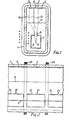
- the display arrangement consists of a long glass tubular envelope 1 of approximately rectangular cross-section, a portion of which constitutes a fluorescent screen 2, and carries three longitudinal stripes 3, 4 and 5 of red, green and blue phosphor respectively.
- the envelope is sealed at both ends (not shown) and is evacuated to a high level of vacuum.
- a single elongate cathode 6 is positioned towards the end of the rectangular section of the envelope which is away from the screen 2 and the cathode 6 is almost entirely enclosed by means of a field electrode 7.
- the field electrode 7 and the cathode 6 constitute an electron gun 9 which is arranged to produce a flood beam of electrons, the width of which is determined primarily by the opening 10 in the field electrode 7.
- a mesh electrode 11 is positioned between the electron gun and the screen 2.
- emission of electrons from the electron gun can be controlled by the potential applied to the field electrode 7 with respect to the cathode 6.
- the angle at which the electron beam emerges from the gun it can be caused to strike just one of the three stripes, 3, 4 or 5 so that a red, green or blue display can be selected at will.
- Figure 1 the trajectory of the electron beam when no lateral deflection is applied to it, is illustrated in chain line 12. In this instance, it strikes the green stripe 4 and produces a correspondingly coloured patch of intense illumination.
- typical voltages are as follows. A very high potential is applied to the inner surface of the screen 2 and is typically about + 7KV. The mesh electrode is held at +10V and the field electrode 7 is held at the potential of +10V also.
- All potentials are with respect to the nominal earth potential of the cathode 6. Under the conditions in which the stripe 4 is illuminated by the electron beam, no magnetic field is applied to the display arrangement. The electrons are emitted from the cathode 6 towards the mesh electrode 11 in a direction which is transverse to the run of the cathode 6. It will be noted that the width or spread of the flood beam is dictated by the width of the opening 10 and that the flood beam electron continues to diverge in an almost linear manner until it reaches the mesh electrode 11 which is held at +lOV. When the electrons reach the mesh electrode 11, they are greatly influenced by the very high potential on the screen 2 and are accelerated in a very rapid manner so as to strike the phosphor 4 with high energy.
- the brightness of the display can be determined by pulse width modulation of the potential on the field electrode 7.
- the cathode is a directly heated filament, that is to say its temperature is raised to that at which copious emission of the electrons takes place by passing an electric current through it.
- the resistance of the filament is chosen so as to provide the required temperature rise.
- the electron beam is contained within the electron gun by applying a potential of -2V to the field electrode 7, instead of the normal potential of +10V.
- the pulse repetition rate of the pulses applied to the field electrode should be well above the flicker threshold of the eye, so that an observer can see a continuously present display.
- the envelope 2 is of an elongate nature and that a number of separate electron guns 20, 21 and 22 are positioned along the length of the single continuous filamentary cathode 6.
- the electron guns are spaced apart slightly from each other and at each of these positions an external electric coil 23 and 24 is positioned (only two coils are shown, but in practice a large number of guns and coils could be provided).
- These constitute electro-magnets which produce a strong magnetic field when current is passed through them.
- the direction of the magnetic field is along the length of the filament and the polarity of the magnetic field is altered by changing the direction of current flow. In practice all coils will be arranged to produce a magnetic field of the same polarity at particular instants of time.
- the same source of power can be used to heat the cathode and to energise the electro-magnetic coils, the coils being energised during intervals between heater pulses,since it is only during the intervals that the electron beam is allowed to emerge from the gun.
- the device operates in a binary manner, that is to say, a predetermined field strength of one polarity or the other is applied if the red or blue patches of colour are required, whereas no field is applied if a green illumination is required.
- a sequence of positive magnetic field, negative magnetic field, and no magnetic field is applied by all of the magnetic coils in steps. If that colour corresponding to the step in the sequence is required to be illuminated, then a potential of +10V is applied to the field electrode 7 in synchronism - if that particular colour is not required, then a potential of -2V is applied to inhibit electron emission.
- a large number of the display arrangements each having a large number of separate controllable electron guns, can be mounted side by side to produce a large two- dimensional display area with extremely good optical resolution and control over the individual pixels in the display.
Landscapes
- Physics & Mathematics (AREA)
- General Physics & Mathematics (AREA)
- Engineering & Computer Science (AREA)
- Theoretical Computer Science (AREA)
- Cathode-Ray Tubes And Fluorescent Screens For Display (AREA)
- Discharge Lamps And Accessories Thereof (AREA)
Applications Claiming Priority (2)
| Application Number | Priority Date | Filing Date | Title |
|---|---|---|---|
| GB8321147 | 1983-08-05 | ||
| GB08321147A GB2144576B (en) | 1983-08-05 | 1983-08-05 | Display arrangements |
Publications (2)
| Publication Number | Publication Date |
|---|---|
| EP0133784A2 true EP0133784A2 (de) | 1985-03-06 |
| EP0133784A3 EP0133784A3 (de) | 1989-04-26 |
Family
ID=10546875
Family Applications (1)
| Application Number | Title | Priority Date | Filing Date |
|---|---|---|---|
| EP84305132A Withdrawn EP0133784A3 (de) | 1983-08-05 | 1984-07-27 | Anzeigevorrichtung |
Country Status (4)
| Country | Link |
|---|---|
| US (1) | US4695764A (de) |
| EP (1) | EP0133784A3 (de) |
| JP (1) | JPS60100361A (de) |
| GB (1) | GB2144576B (de) |
Families Citing this family (3)
| Publication number | Priority date | Publication date | Assignee | Title |
|---|---|---|---|---|
| EP0526663A4 (en) * | 1991-02-27 | 1993-09-22 | Seiko Epson Corporation | Light projecting device |
| EP0527240A4 (en) * | 1991-03-01 | 1993-09-22 | Seiko Epson Corporation | Light projecting device |
| CA2849084C (en) | 2011-09-20 | 2018-07-03 | Pregis Innovative Packaging, Inc. | Tear-assist apparatus |
Family Cites Families (9)
| Publication number | Priority date | Publication date | Assignee | Title |
|---|---|---|---|---|
| GB434868A (en) * | 1933-03-06 | 1935-09-06 | Fernseh Ag | Cathode-ray tubes for the production of pictures in natural colours, particularly for television and like systems |
| US2623190A (en) * | 1950-02-13 | 1952-12-23 | Solo S Roth | Color television system |
| GB728053A (en) * | 1951-01-20 | 1955-04-13 | Standard Telephones Cables Ltd | Voltage indicator tube with two sensitivity ranges |
| NL172945B (nl) * | 1951-10-06 | Rhone Poulenc Ind | Verbetering van de werkwijze voor het stabiliseren en consolideren van grond bevattende samenstellingen. | |
| GB882866A (en) * | 1957-11-27 | 1961-11-22 | Mullard Ltd | Improvements in or relating to cathode-ray devices |
| GB900431A (en) * | 1961-03-06 | 1962-07-04 | Mullard Ltd | Improvements in or relating to cathode-ray tubes |
| US3694686A (en) * | 1970-01-09 | 1972-09-26 | Tokyo Shibaura Electric Co | Unidirectional double deflection type cathode ray tube |
| GB2031220B (en) * | 1978-10-04 | 1983-01-06 | English Electric Valve Co Ltd | Evacuated display tubes |
| GB2057187B (en) * | 1979-08-24 | 1983-08-10 | Elliott Bros | Bem index colour display tubes |
-
1983
- 1983-08-05 GB GB08321147A patent/GB2144576B/en not_active Expired
-
1984
- 1984-07-27 EP EP84305132A patent/EP0133784A3/de not_active Withdrawn
- 1984-08-02 US US06/637,035 patent/US4695764A/en not_active Expired - Fee Related
- 1984-08-06 JP JP59164730A patent/JPS60100361A/ja active Pending
Also Published As
| Publication number | Publication date |
|---|---|
| GB2144576A (en) | 1985-03-06 |
| GB2144576B (en) | 1987-04-15 |
| US4695764A (en) | 1987-09-22 |
| GB8321147D0 (en) | 1983-09-07 |
| EP0133784A3 (de) | 1989-04-26 |
| JPS60100361A (ja) | 1985-06-04 |
Similar Documents
| Publication | Publication Date | Title |
|---|---|---|
| US3855499A (en) | Color display device | |
| JPS6057077B2 (ja) | 表示装置 | |
| KR920006174B1 (ko) | 화상표시장치 | |
| US4707638A (en) | Luminance adjusting system for a flat matrix type cathode-ray tube | |
| US4387322A (en) | Display arrangements | |
| JPH0261949A (ja) | 蛍光性マイクロドットスクリーンとそのアドレッシング方法 | |
| US4791337A (en) | Lighting method for vacuum fluorescent display with reduced flickering | |
| US4695765A (en) | Display arrangements | |
| EP0133784A2 (de) | Anzeigevorrichtung | |
| US4306178A (en) | Display arrangements | |
| KR950034381A (ko) | 전자총 및 음극선관 그 구동방법 | |
| US5949395A (en) | Flat-panel matrix-type light emissive display | |
| US3331983A (en) | Direct-view storage tube and method of erasure | |
| EP0101195B1 (de) | Anzeigevorrichtung | |
| US2907909A (en) | Light source | |
| GB2045521A (en) | Cathode ray tube light sources | |
| US2879446A (en) | Electronic device | |
| US2755413A (en) | Gas filled projector tubes for television | |
| US5977939A (en) | Gas flat display tube | |
| US4193014A (en) | Display arrangements | |
| EP0238799B1 (de) | Luminanzeinstellungssystem für eine Kathodenstrahlröhre der Flachmatrixart | |
| EP0143669B1 (de) | Bildwiedergabevorrichtung | |
| US4810928A (en) | Cathode-ray tube for constituting large picture display apparatus | |
| US3406310A (en) | Direct-viewing color display storage device | |
| GB1569973A (en) | Display arrangements |
Legal Events
| Date | Code | Title | Description |
|---|---|---|---|
| PUAI | Public reference made under article 153(3) epc to a published international application that has entered the european phase |
Free format text: ORIGINAL CODE: 0009012 |
|
| AK | Designated contracting states |
Designated state(s): AT BE CH DE FR IT LI LU NL SE |
|
| PUAL | Search report despatched |
Free format text: ORIGINAL CODE: 0009013 |
|
| AK | Designated contracting states |
Kind code of ref document: A3 Designated state(s): AT BE CH DE FR IT LI LU NL SE |
|
| STAA | Information on the status of an ep patent application or granted ep patent |
Free format text: STATUS: THE APPLICATION HAS BEEN WITHDRAWN |
|
| 17P | Request for examination filed |
Effective date: 19890506 |
|
| 18W | Application withdrawn |
Withdrawal date: 19890531 |
|
| RIN1 | Information on inventor provided before grant (corrected) |
Inventor name: NIXON, RALPH DESMOND |