EP0133746A2 - Abführmechanismus für den Gussstrang beim horizontalen Stranggiessen - Google Patents
Abführmechanismus für den Gussstrang beim horizontalen Stranggiessen Download PDFInfo
- Publication number
- EP0133746A2 EP0133746A2 EP84304332A EP84304332A EP0133746A2 EP 0133746 A2 EP0133746 A2 EP 0133746A2 EP 84304332 A EP84304332 A EP 84304332A EP 84304332 A EP84304332 A EP 84304332A EP 0133746 A2 EP0133746 A2 EP 0133746A2
- Authority
- EP
- European Patent Office
- Prior art keywords
- shaft
- piston
- withdrawal mechanism
- disc
- lever assembly
- Prior art date
- Legal status (The legal status is an assumption and is not a legal conclusion. Google has not performed a legal analysis and makes no representation as to the accuracy of the status listed.)
- Withdrawn
Links
Images


Classifications
-
- B—PERFORMING OPERATIONS; TRANSPORTING
- B22—CASTING; POWDER METALLURGY
- B22D—CASTING OF METALS; CASTING OF OTHER SUBSTANCES BY THE SAME PROCESSES OR DEVICES
- B22D11/00—Continuous casting of metals, i.e. casting in indefinite lengths
- B22D11/12—Accessories for subsequent treating or working cast stock in situ
- B22D11/128—Accessories for subsequent treating or working cast stock in situ for removing
- B22D11/1284—Horizontal removing
Definitions
- This invention relates to a withdrawal mechanism for withdrawing a casting from the mould of a horizontal continuous casting machine.
- a horizontal continuous casting machine is provided with a withdrawal mechanism whereby the casting is withdrawn in an intermittent manner from the mould in which it is formed.
- the withdrawal mechanism usually comprises at least one pair of pinch rolls which engage with opposite sides of the casting and at least one of each pair of rolls is driven in order to displace the casting.
- the casting is not withdrawn continuously but is withdrawn in a number of successive cycles, with each cycle having a withdrawal phase, a pause phase and a push phase in which a force is applied to the casting to displace it in the direction towards the mould in which it is formed.
- the pause phase is between the withdrawal phase and the push phase, but the push phase can be arranged between the withdrawal phase and the,pause phase.
- a withdrawal mechanism for a horizontal continuous casting machine comprises a pair of pinch rolls engageable with opposite sides of a casting to be withdrawn from a mould of a continuous casting machine, one of said rolls being in driving relation with a rotatable shaft, characterised-in that a disc is rigidly mounted on the shaft; a pivoted lever assembly is displaceable with respect to the disc; means are provided for displacing the lever assembly in both directions of rotation about the pivot; a clutch is provided for releasably coupling the lever assembly to the disc to transmit angular displacement of the lever assembly to the disc; and a brake mechanism is provided for preventing angular rotation of the shaft.
- the clutch is actuated to couple the lever assembly to the disc and the lever assembly is -pivoted about its pivot in one direction of rotation in order to rotate the disc and, hence, the shaft in one direction of rotation.
- the brake mechanism is applied to prevent further angular rotation of the shaft and the clutch is released while the lever assembly is pivoted in the other direction of rotation about the pivot.
- the clutch is then actuated to re-couple the lever assembly to the disc while the brake mechanism is disengaged to allow angular rotation of the shaft and, in this way, a limited movement of the lever assembly in the opposite direction of rotation is transmitted to the rotatable shaft.
- the movement of the shaft is, thus, through a predetermined angle in one direction, followed by a pause in which the shaft is stationary, followed by a limited rotation in the opposite direction.
- the means for displacing the lever assembly may comprise a piston-cylinder device coupled to the lever assembly, or it may comprise a cam arrangement acting on the lever assembly.
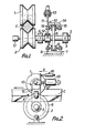
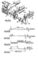
- a withdrawal mechanism for a horizontal continuous casting machine consists of a pair of pinch rolls 1, 2 which engage with opposite sides of a casting C formed in a mould (not shown).
- Pinch roll 1 is freely rotatable about a shaft (not shown) and it may be urged against the upper surface of the casting.
- Pinch roll 2 is mounted on a shaft 3 which, in turn, is mounted in bearings 4, 5.
- a disc 6 is rigidly secured to the shaft 3 to rotate with it.
- a brake mechanism 7 has.a fixed calliper 8 with a pair of pads 9 which can be displaced into engagement with opposite sides of the disc so that the friction between the pads and the disc prevents rotation of the disc and, hence, prevents rotation of the shaft 3.
- a lever assembly 10 has a lever 11 mounted at one end on a sleeve 12 which fits over, and is freely rotatable relative to, the shaft 3. The opposite end of the lever is pivotally connected to the piston rod 12' of a piston-cylinder device 13.
- the piston-cylinder device 13 is either a double-acting device or is a single-acting device provided with a spring return, whereby the lever 11 can be pivoted in both directions of movement relative to the axis of the shaft 3.
- a bracket 14 connected to the lever 11 has a pair of pads 15 which are positioned on opposite sides of the disc 6.
- a linear electrical transducer 16 is rigidly secured to a support (not shown) and has one portion connected to the lever assembly so that the transducer can produce an electrical signal representative of the position of the piston of the piston-cylinder device and, hence, of the lever arm.
- a rotary transducer 17 coupled to the shaft 3 gives an indication of the angular position of the shaft and the pinch roll 2.
- the forward movement of the casting C out of the mould is brought about by actuating the clutch mechanism so that the lever assembly 10 is coupled to the disc 6.
- the piston-cylinder device 13 is energised under the control of a closed loop control system which regulates valves which control the flow and pressure of hydraulic fluid applied to the piston-cylinder device.
- the piston rod urges the lever assembly to rotate in the anticlockwise direction, as shown in Figure 2, causing the disc and the shaft 3 to be rotated in an anticlockwise direction through a limited angle.
- the clutch and the brake mechanism can be of any convenient form, being hydraulically, pneumatically, or electrically operated, the main criteria being that they should be very responsive to high speed application and release.
- the sequencing of the operating phases of the piston-cylinder device, clutch and brake mechanisms is controlled by an element in the control system.
- This may take the form of a hard-wired sequential controller or a computer programme, either of which will receive a signal from the position transducer 16. This signal is compared with the preset signals in the control system and, when these signals correspond, control signals are sent to the clutch and brake to operate them in order to bring about the correct operation of the mechanism.
- Slip can be detected by comparing the output from the linear position transducer 16 with the output of the rotary position transducer 17.
- Roll slip can be detected by comparing the output of transducer 17 with the output of another transducer (not shown) in contact with pinch roll I or with the casting C.
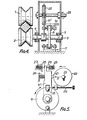
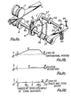
- a lever 11' forming part of the lever assembly, has a cam follower 21 connected to it which bears against a cam surface on a rotatable member 22 rigidly mounted on a drive shaft 23.
- a spring 24 ensures that the follower remains in contact with the cam surface.
- the lever 11' carries a pair of contacts 25, 26 at its upper free end and these are engageable with fixed electrical contacts 27, 28, respectively, positioned at the ends of the path of travel,'of the lever 11'.
- the shaft is rotatable at a constant speed for each cycle by any convenient means. Rotation of the cam 22 causes the lever arm to be pivoted about its pivot and, when the clutch 14, 15 is engaged, the displacement of the lever arm is transmitted to the disc 6 and, consequently, to the shaft 3.
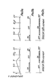
- the cycle starts at point I where the clutch is on and the brake is off.
- the follower moves under the influence of the cam to its maximum displacement at point II.
- the brake is applied to decelerate the casting to zero velocity and hold it stationary.
- the clutch is released, thus allowing the cam follower to return to its home position less a distance Xp which is the push back distance.
- the clutch is reapplied and the brake is released and the cam profile allows the lever to return to its initial position under the influence of the spring 24 taking the disc and the shaft 3 with it. This is the push back phase of the cycle.
- the brake and the clutch can be either hydraulically, pneumatically or electrically operated, the main criteria being that they should be very responsive to high speed application and release.
- the actuation of the clutch and the brake mechanasms is as shown in Figures 6b and 6c and this phasing is triggered by the operation of the contatcs 25, 27 and 26, 28, respectively.
- the push back pressure can be adjusted during the cast by varying the pre-compression of the push back spring 24 and the push back travel can be attenuated by the adjustment of a push back screw 29.
- the withdrawal phase can be attenuated during the cast by the early actuation of the brake and release of the clutch during the withdrawal period.
- the shaft 3 has a pair of discs 6, 6' attached to it and a pair of lever assemblies 10, 10' associated one with each of the discs.
- a pair of cams 22, 22' are provided on the drive shaft, the cams have different cam profiles and, by energising the clutch associated with the chosen lever assembly and the common brake, the displacement of the lever assembly can be brought about depending upon which cam is chosen.
- Figures 9a - 9c indicate the alternative forms of angular displacement of the shaft which can be obtained with two cams of different profiles.
- the casting operator will be able to switch from one casting pattern to another by selecting the appropriate cam and isolating in the OFF position the clutch associated with the other cam. This selection can be made either before or during the cast.
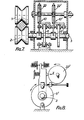
- a casting C formed in a horizontal continuous casting mould (not shown) is withdrawn from the mould by a mechanism including a pair of pinch rolls 1, 2 which engage with opposite sides of the casting.
- the pinch roll 2 is mounted on a first shaft 33 and a transducer 34 coupled to the shaft provides a signal of the angular position of the shaft.
- a similar transducer 35 is coupled to the shaft to which the pinch roll 1 is connected.
- At the opposite end of the shaft 33 there is one element of a clutch 36 and the other element is connected to the adjacent end of a farther shaft 3 7 which is aligned with the shaft 33.
- the clutch can be of any convenient form and, when it is disengaged, the shafts have relative rotation between them but, when the clutch is engaged, the shafts move together.
- a toothed wheel 38 is mounted on the shaft 33 and a pawl 39 engages with the spaces between the teeth on the wheel.
- the teeth are inclined from the radial position so that, in the position shown in Figure 10a, the wheel 38 can rotate anticlockwise relative to the pawl, but the pawl prevents.it from rotating in a clockwise direction.
- the pawl 39 is connected to a bracket 40 to which the piston 41 of piston-cylinder device 42 is connected and to which a linear transducer 43 is also connected.
- the piston-cylinder device 42 and the wheel and pawl provides intermittent motion of the shaft 33 in the anticlockwise direction.
- the second shaft 37 carries a crank lever 44 to which a bracket 45 is pivotally connected.
- a piston-cylinder device 46 has its piston connected to the bracket and a linear transducer 47 is also connected to the bracket.
- the forward motion of the pinch rolls is provided by the piston-cylinder device 42 driving the pinch roll 2 via the pawl and wheel mechanism 38, 39.
- Control of the displacement of the piston-cylinder device, its velocity, and its acceleration is achieved by the employment of a closed loop control system which controls a hydraulic valve which, in turn, regulates the flow and pressure of hydraulic fluid to and from the piston-cylinder device.
- the linear transducer 43 provides a positive feedback to the control system to thereby close the control position loop.
- Pressure transducers (not shown) are installed at the ports on the piston-cylinder device in order to provide a control pressure loop to the system.
- the clutch can be hydraulically, pneumatically, or electrically operated.
- a small reverse motion of pushback is required towards the end of the cycle and this is shown as a negative veocity at point II in Figure 10e.
- the pushback motion is produced by the piston-cylinder device 46 and the motion is controlled by a closed loop similar to that referred to above.
- the feedback signals are generated by the linear position transducer 47 and pressure transducers (not shown) monitoring the hydraulic pressure at the ports on the piston-cylinder device 46.
- the feedback for the position loop in both forwards and backwards directions may be taken from the transducers 35 which monitors the actual position of the casting.
- the clutch is disengaged and remains disengaged until the end of the forward motion phase of the next cycle.
- the sequencing of the operating phases of the piston-cylinder devices 42, 46 and the clutch 36 is controlled by an element of the control system. This may take the form of a hard wired sequential controller or a computer programme, either of which will receive trigger signals from the position transducers 34, 43 and 47.
- Any slip which may occur at the clutch can be detected by comparing the signals from the linear transducer 47 and a rotary transducer 34 coupled to the drive pinch roll. Roll slip can be detected by comparing the outputs from transducers 34 and 35.
- the pawl 39 is displaced by the action of a rotatable cam 50 mounted on a drive input shaft 51.
- a spring return is provided to make sure that a follower of the pawl is always in engagement with the cam surface of the cam 50.
- a further cam 52 mounted on the shaft 51 serves as a rotary switch to open and close a pair of contacts 53 in the electrical circuit of the clutch 36 which, in this embodiment, is electrically operated.
- a still further cam 55 mounted on the shaft 51 has a follower 57 in the form of a lever which is mounted on the shaft 37. This lever is urged against the cam surface by a spring 60 and rotation of the cam 55 causes the shaft 37 to be displaced in both directions of rotation.
- the forward motion of the casting C is produced by the cam 50 acting on the pawl and driving the shaft 33 via the pawl and toothed wheel.
- the cam is profiled such that its follower moves according to the graph shown in Figure llb and the useful work is done between points I and II on that graph. This is the acceleration and constant velocity phase of the cycle.
- cam 52 closes the electrical contacts and engages the clutch 36.
- the clutch is prevented from rotating by the lever 57 restrained by the cam 55.
- the clutch retards the forward motion of the casting and holds it back throughout the pause phase and will remain engaged during the pushback phase.
- Cam 55 imports a motion to its lever 57, as shown in Figure lld.
- the cam moves the lever 57 downwards, thereby producing a reverse rotation of the clutch transmitted via the shaft 33 to the pinch rolls, thus applying a pushback motion to the casting.
- the clutch is disengaged by the opening of the contacts 53. This isolates the roll from the return motion of the cam lever 57 as it returns to its rest position under the action of the spring 60.
- cam profile of cams 50, 55 are such that the velocity of the cam follower of the pawl at point V in Figure llb is greater than the peripheral velocity of the ratchet wheel, otherwise damage will be done to the mechanism.
- Pushback distance can be regulated by adjusting a screwed stop 61 which restricts the return movement of the cam lever 57.
- Pull distance can also be regulated by a similar stop which will restrict the return motion of the follower of cam 50. This, however, will result in some loss of control over the acceleration of the casting.
- the mechanism is driven by rotation of the cam shaft 51 and this may be driven by a drive means of any form, such as an electric, hydraulic, or pneumatic motor. It is desirable that the drive should be a variable speed motor so as to enable the withdrawal cycle frequency to be varied. It will be appreciated, however, that the speed will remain constant during one or more of a number of cycles.
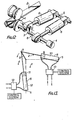
- two hydraulic piston-cylinder devices 6 have their pistons connected to respective cranks 3 on a crankshaft 8.
- the cranks are positioned at 90° to each other on the shaft 8.
- the cylinders of the piston-cylinder devices are pivotaily mounted by way of bearings 5 so as to permit the cylinders to follow the motion of the cranks 3.
- the cylinders could be held in fixed positions and motion transmitted through sliders attached to the connecting rod.
- a pair of pinch rolls 1 are arranged to engage against opposite sides of a casting 2 produced in a horizontal continuous casting mould (not shown).
- the lower of the two pinch rolls is connected to the crankshaft 8 and rotation of the crankshaft imparts linear motion to the casting 2.
- a position measuring device 4 is connected to the crankshaft to give an electrical signal representative of the angular position of the shaft and, hence, the lower pinch roll.
- cranks 3 can be inclined to each other by any convenient angle, other than 180°.
- the pair of piston-cylinder devices 6 have their pistons connected to the same crank on the crankshaft 8.
- the two piston-cylinder devices are mounted by way of the pivots 5 such that the direction of movement of the piston of one device relative to its cylinder is inclined to the direction of movement of the piston of the other device relative to its cylinder.
- the pivots 5 are positioned on a pair of mutually normal axes, indicated by broken lines, so that the direction of movement of the piston of one device relative to its cylinder is substantially normal to that of the other device.
- Single-acting cylinders can be used instead of double-acting cylinders, but then four cylinders are required with a corresponding complication to the control circuit for each piston-cylinder device.
- Each piston-cylinder device has the ports on opposite sides of its piston connected by fluid pipes to a servo valve 13 which is connected to fluid supply and return lines.
- Each servo valve is controlled by signals from a control system.
- FIG. 14 A control system suitable for bringing about the operation of the apparatus shown in Figure 13 is shown diagrammaticaly in Figure 14.
- the position measuring device 4 which is coupled to the shaft 8 is used to determine the changeover points 1, 2, 3 and 4 shown in Figure 13. It also serves as a feedback element for controlling the position of the pinch roll.
- the operating range of 90° for each push/pull cycle of the piston-cylinder device can be extended by a small amount so that a push or pull cycle of the pinch roll, if it is short, can be completed by one cylinder rather than causing a slight discontinuity by switching over to the other cylinder.
- a position control loop element 21 receives an error signal being the difference between a position reference signal and the output position signal of the device 4.
- Element 21 has a variable limit output and so it can be considered to set the maximum velocity of the pinch rolls.
- Element 22 has an adjustable rate limit and, therefore, is used for setting the acceleration rate.
- Inverter 23 is used to change the polarity of the output signal from element 22, if necessary, to cause the piston-cylinder device to push or pull according to its position in the 360° crank cycle.
- the contacts 24 are controlled from a control logic circuit 25 which receives a signal from the transducer 4.
- An element 26 differentiates the position signal from transducer 4 to provide a velocity feedback signal which is subtracted from the signal from the contacts 24.
- a gain modifier is included in the form of an element 29 in order keep the performance constant throughout the rotation.
- the gain from the element 29 is determined according to the position of the crank as measured by transducer 4.
- the output from this element is compared with the feedback signal from element 28 to form a pressure responsive signal which is amplified and supplied to servo valve 13.
- control for one cylinder is shown in Figure 14 and an identical circuit, apart from the control logic 25 and the transducer 4, is required for the other cylinder.
- Discrete control elements are shown in Figure 14 in order.to facilitate the understanding of the control system but, in practice, a computer would be used to carry out the operation of these elements.
Landscapes
- Engineering & Computer Science (AREA)
- Mechanical Engineering (AREA)
- Transmission Devices (AREA)
- Continuous Casting (AREA)
Applications Claiming Priority (6)
| Application Number | Priority Date | Filing Date | Title |
|---|---|---|---|
| GB8317780 | 1983-06-30 | ||
| GB8317779 | 1983-06-30 | ||
| GB838317780A GB8317780D0 (en) | 1983-06-30 | 1983-06-30 | Withdrawal mechanism for continuous casting machine |
| GB838317779A GB8317779D0 (en) | 1983-06-30 | 1983-06-30 | Drive mechanism |
| GB838317778A GB8317778D0 (en) | 1983-06-30 | 1983-06-30 | Drive mechanism |
| GB8317778 | 1983-06-30 |
Publications (2)
| Publication Number | Publication Date |
|---|---|
| EP0133746A2 true EP0133746A2 (de) | 1985-03-06 |
| EP0133746A3 EP0133746A3 (de) | 1985-05-15 |
Family
ID=27262152
Family Applications (1)
| Application Number | Title | Priority Date | Filing Date |
|---|---|---|---|
| EP84304332A Withdrawn EP0133746A3 (de) | 1983-06-30 | 1984-06-26 | Abführmechanismus für den Gussstrang beim horizontalen Stranggiessen |
Country Status (1)
| Country | Link |
|---|---|
| EP (1) | EP0133746A3 (de) |
Family Cites Families (2)
| Publication number | Priority date | Publication date | Assignee | Title |
|---|---|---|---|---|
| GB1271051A (en) * | 1970-02-25 | 1972-04-19 | Siemens Ag | Driving system for continuous casting plants |
| JPS5659570A (en) * | 1979-10-17 | 1981-05-23 | Nippon Kokan Kk <Nkk> | Driving method of ingot drawing roll in horizontal continuous casting machine |
-
1984
- 1984-06-26 EP EP84304332A patent/EP0133746A3/de not_active Withdrawn
Also Published As
| Publication number | Publication date |
|---|---|
| EP0133746A3 (de) | 1985-05-15 |
Similar Documents
| Publication | Publication Date | Title |
|---|---|---|
| SU820651A3 (ru) | Устройство дл позиционировани РАбОчЕгО ОРгАНА | |
| US4319864A (en) | Apparatus for producing rapid movement and smooth braking and a precisely defined final position of a movable robot arm | |
| JPH0122135B2 (de) | ||
| US5975858A (en) | Hydraulic drive unit of a press machine and swash plate type variable capacity axial piston pump to use for said device | |
| NL8403025A (nl) | Klepaandrijforgaan. | |
| US3798995A (en) | Brake operating lever system | |
| JP2022109228A (ja) | タンパストローク調整 | |
| JPS5919774B2 (ja) | パンチ機械のタレツト割出装置 | |
| US4588364A (en) | Clamp mechanism | |
| EP0133746A2 (de) | Abführmechanismus für den Gussstrang beim horizontalen Stranggiessen | |
| US3413862A (en) | Cam controlled actuator including intermittent torque means | |
| JP3063862B2 (ja) | 鍛造機のためのマニピュレータ | |
| JP2005325959A (ja) | 電気油圧アクチュエータ | |
| JPH078396B2 (ja) | 鍛造プレス機の自動移動ビームを制御するための方法及びこの方法を実施するための制御装置 | |
| US6561331B1 (en) | Transmission unit for a vehicle | |
| US2224257A (en) | Mechanism for eliminating backlash | |
| CN1047992A (zh) | 动力传动装置 | |
| JPS58128503A (ja) | 水圧弁制御兼フイ−ドバツク装置 | |
| US2984000A (en) | Pipe coupling screw-on machine controls | |
| US4907435A (en) | System for monitoring the position of a machine component | |
| JPS6068148A (ja) | 引出し機構 | |
| JPS608502A (ja) | 油圧シリンダとその制御方法 | |
| JPH0444320Y2 (de) | ||
| HU200131B (en) | Electropneumatic remote-switching device particularly for switching the gears of synchronized mechanic speed box of motor vehicles | |
| US5896802A (en) | Rotating apparatus for a diesel motor |
Legal Events
| Date | Code | Title | Description |
|---|---|---|---|
| PUAI | Public reference made under article 153(3) epc to a published international application that has entered the european phase |
Free format text: ORIGINAL CODE: 0009012 |
|
| AK | Designated contracting states |
Designated state(s): AT BE CH DE FR GB IT LI LU NL SE |
|
| PUAL | Search report despatched |
Free format text: ORIGINAL CODE: 0009013 |
|
| AK | Designated contracting states |
Designated state(s): AT BE CH DE FR GB IT LI LU NL SE |
|
| STAA | Information on the status of an ep patent application or granted ep patent |
Free format text: STATUS: THE APPLICATION IS DEEMED TO BE WITHDRAWN |
|
| 18D | Application deemed to be withdrawn |
Effective date: 19860115 |
|
| RIN1 | Information on inventor provided before grant (corrected) |
Inventor name: DENDLE, DAVID WILLIAM Inventor name: STONECLIFFE, DAVID |