EP0133571B1 - Rotierende elektrische Maschine flacher Bauart - Google Patents
Rotierende elektrische Maschine flacher Bauart Download PDFInfo
- Publication number
- EP0133571B1 EP0133571B1 EP19840109371 EP84109371A EP0133571B1 EP 0133571 B1 EP0133571 B1 EP 0133571B1 EP 19840109371 EP19840109371 EP 19840109371 EP 84109371 A EP84109371 A EP 84109371A EP 0133571 B1 EP0133571 B1 EP 0133571B1
- Authority
- EP
- European Patent Office
- Prior art keywords
- rotor
- rotary electric
- layers
- electric machine
- disposed
- Prior art date
- Legal status (The legal status is an assumption and is not a legal conclusion. Google has not performed a legal analysis and makes no representation as to the accuracy of the status listed.)
- Expired
Links
Images

Classifications
-
- H—ELECTRICITY
- H02—GENERATION; CONVERSION OR DISTRIBUTION OF ELECTRIC POWER
- H02K—DYNAMO-ELECTRIC MACHINES
- H02K21/00—Synchronous motors having permanent magnets; Synchronous generators having permanent magnets
- H02K21/12—Synchronous motors having permanent magnets; Synchronous generators having permanent magnets with stationary armatures and rotating magnets
- H02K21/24—Synchronous motors having permanent magnets; Synchronous generators having permanent magnets with stationary armatures and rotating magnets with magnets axially facing the armatures, e.g. hub-type cycle dynamos
-
- H—ELECTRICITY
- H02—GENERATION; CONVERSION OR DISTRIBUTION OF ELECTRIC POWER
- H02K—DYNAMO-ELECTRIC MACHINES
- H02K3/00—Details of windings
- H02K3/04—Windings characterised by the conductor shape, form or construction, e.g. with bar conductors
- H02K3/26—Windings characterised by the conductor shape, form or construction, e.g. with bar conductors consisting of printed conductors
-
- H—ELECTRICITY
- H02—GENERATION; CONVERSION OR DISTRIBUTION OF ELECTRIC POWER
- H02K—DYNAMO-ELECTRIC MACHINES
- H02K9/00—Arrangements for cooling or ventilating
- H02K9/02—Arrangements for cooling or ventilating by ambient air flowing through the machine
- H02K9/04—Arrangements for cooling or ventilating by ambient air flowing through the machine having means for generating a flow of cooling medium
- H02K9/06—Arrangements for cooling or ventilating by ambient air flowing through the machine having means for generating a flow of cooling medium with fans or impellers driven by the machine shaft
Definitions
- the present invention relates to an axial air gap type rotary electric machine such as a printed circuit motor, a multi-phase alternator or a flat motor. More particularly, the invention is concerned with an improvement in a cooling mechanism of the rotary electric machine of the type specified above.
- a flat type rotary electric machine according to the preamble of claim 1 is known from DE-U-1 826 690, CH-A-584 985 or US-A-3 953 751, for example.
- the rotary electric machine of the type specified above is provided with a flat coil comprising an annular carrier member of an electrically insulating material and windings carried by the carrier member.
- the windings are formed by a plurality of annular rows of generally radially extending and axially thin conductors each having radially inner and outer end sections and an intermediate section.
- the flat coil is disposed in the axial air gap type rotary electric machine such thatthe opposite sides or end faces of the flat coil are faced towards magnets.
- the flat coil serves as a stator coil and has opposite end faces disposed in opposite relationship to magnets carried by a pair of rotors mounted on a shaftfor rotation therewith so that, when the rotors are rotated with the shaft, the flat coil cooperates with the magnets to generate induced electromotive force.
- the intermediate sections of the conductors of the flat coil are faced towards the magnets of the rotors and are effective to produce the electromotive force.
- the intermediate section of each conductor of the flat coil is termed herein as an "effective section”.
- the windings of theflatcoils of the prior art axial air gap type rotary electric machines are formed either by wires each having a round cross section of a uniform diameter throughout its length, as seen in flat motors, or by conductor segments each having a uniform axial thickness, as seen in printed circuit motors. Because of the structure of the flat coil of this kind of rotary electric machines, the flat coil has the disadvantage that the radially and axially inner parts of the flat coil cannot be cooled easily and thus suffer from high or elevated temperatures.
- U.S. Patent No. 3,231,774 discloses a three-phase armature coil formed by an annular disc or carrier member and three-phase windings carried by the carrier member.
- a plurality of such annular carrier members are stacked to form a laminated structure and the windings are connected in parallel relationship to each other to increase the output.
- U.S. Patent No. 3,500,095 discloses a laminated structure of a flat DC motor armature coil which is adapted to be supplied with a DC current from a brush unit.
- a temperature rise is caused particularly in the axially inner parts of the annular effective zone of the flat coil.
- the axial distance between the magnets disposed on the opposite sides of the flat coil is undesirably increased so that the magnetic reluctance of the path of the magnetic flux produced by the magnets is increased with the resultant disadvantage that the efficiency of the rotary electric machine is lowered.
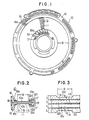
- a flat coil 10 includes annular rows of a large number of radial conductor segments 12 secured to and carried by a supporting disc or annular carrier member 11 of an electrically insulating material.
- Each of the conductor segments 12 has an effective section disposed within an annular zone of the flat coil designated by B and end sections disposed radially inwardly and outwardly of the effective section.
- the radially inner and outer end sections have end extremities bent to extend axially with respect to the flat coil to form radially outer and inner coil fins 16 and 17, as will be described in more detail later.
- the flat coil 10 further includes radially outer and inner annular holders 18 and 19 secured to the radially outer and inner peripheral edges of the annular carrier member 11 and provided with holder fins 18a and 19a each projecting axially outwardly of the carrier member 11, as will be described in more detail later.
- the inner holder 19 defines therein a central opening for a shaft of an axial air gap type rotary electric machine which is equipped with the flat coil 10.
- the coil fins 16 and 17 have been described as being provided on all of the conductor segments 12, but it will be apparent to those skilled in the art that only some or a selected number of the conductor segments may be provided with such coil fins provided that the coil fins are disposed at equal circumferential intervals.
- the conductor segments 12 are arranged not solely on the outer surfaces (end faces) of the annular carrier member 11; namely, the segments 12 are arranged in a plurality of layers, as will be described hereunder.
- Fig. 2 is an axial sectional view of a half of the flat coil shown in Fig. 1. Strictly speaking, however, Fig. 2 is not a section taken on a single plane but is a composite sectional view showing all the layers of the conductor segments which, in fact, are angularly and circumferentially offset from each other.
- the flat coil 10 includes four layers of conductor segments 12a, 12b, 12c and 12d and three insulating layers 11a, 11b and 11c which form the annular carrier member 11 and are sandwiched between the layers of the conductor segments, respectively.
- Two layers of conductor segments 12a and 12b and the insulating layer 11a a form a module 10a, while the other two layers of conductor segments 12c and 12d and the insulating layer 11c form another module 10b.
- the two modules 10a and 10b are stacked together with the third insulating layer 11 b interposed therebetween to form the laminated structure shown in Fig. 2.
- the conductor segments 12 and 12d will be called “conductor segments of the outermost layers", whereas the conductors 12b and 12c will be termed "conductor segments of the inner layers”.
- the annular rows of layers of the conductor segments can be fabricated by employing any one of the pressing, electroforming and electrolytic techniques disclosed in EP-A-0 096 415 (European Patent Application No. 83105587.6). The disclosure in the earlier European patent application referred to is incorporated herein by reference. Alternatively, the conductor segments can be made by die-casting technique.
- the conductor segments 12a and 12b are disposed on the opposite faces of the insulating layer 11 a and arranged in the pattern shown in Fig. 1. Similarly, the other conductor segments 12c and 12d are disposed and arranged on the opposite faces of the insulating layer 11c.
- the radially inner and outer ends of the conductor segments 12a or 12d on a first face ofthe insulating iayerlla or 11c are respectively electrically connected by welding or brazing to the radially inner and outer ends of the conductor segments 12b or 12c on the second face of the insulating layer 11a or 11c so that the electrically connected conductor segments on the opposite faces of the insulating layer 11a a or 11c c form at least one winding (three windings in the case of a three-phase rotary electric machine).
- the radially outer and inner end extremities of the connected ends of the conductor segments are bent to extend axially of the flat coil 10 to form the aforementioned coil fins 16 and 17, as best seen in Fig. 2.
- the coil fins 16 and 17 advantageously increase the heat radiation surface areas of the flat coil 10.
- the radially outer and inner annular holders 18 and 19, which have been mentioned previously, are operative to bind the radially outer and inner peripheral edges of the two modules 10a and 10b and the intermediate insulating layer 11b b so that they are united together to form the flat coil 10.
- the holder fins 18a and 19a, which have also been mentioned previously, are effective to increase the heat radiation surface areas of the flat coil 10.
- the conductor segments 12b and 12c of the inner layers have thicknesses t 1 (measured axially of the flat coil 10) which are substantially uniform throughout the radial lengths of the conductor segments 12b and 12c, whereas the conductor segments 12a and 12d of the outermost layers do not have uniform thicknesses throughout their radial lengths. More specifically, although the radially outer and inner end sections of the conductor segments 12a and 12d of the outermost layers have thicknesses substantially equal to the thicknesses t, of the conductor segments of the inner layers, the effective sections B of the conductor segments 12a and 12d have thicknesses t z less than the thicknesses t1.
- Fig. 4 shows a flat type alternator 20 in which the flat coil 10 described above is employed.
- the flat coil 10 is disposed in the housing and held at its outer periphery between housing parts 24a and 24b.
- a pair of rotors 22a and 22b are disposed on the opposite sides of the flat coil 10 and are secured by a key member to a shaft 26 which rotatably extends through the central opening in the flat coil 10 and is rotatably supported by a pair of bearings 27a and 27b mounted on the housing parts 24a and 24b, respectively.
- a pulley 28 is mounted on the shaft 26 for rotation therewith.
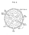
- the rotors 22a and 22b are of similar structure and thus it Will be sufficient to describe the structure of one of the two rotors with reference to Fig. 5.
- Magnet segments 22c or 22d having different polarities are secured to that face of the rotor 22a or 22b which is directed to the flat coil 10 and are arranged alternately on a circle about the axis of the rotor and adjacent to the outer periphery thereof.
- the magnet segments 22c or 22d are circumferentially spaced one from another to define radial grooves 22a-1.
- the rotor is formed therein with axial through-holes or openings 22a-2 and 22b-2 arranged on a circle disposed between the annular row of the magnet segments 22c or 22d and the central shaft hole in the rotor.
- Radially outwardly projecting fan blades 22a-3 or 22b-3 are provided along the outer periphery of the rotor and disposed adjacent to the radially outer ends of the radial grooves 22a-1, respectively.
- annular rows of fan blades 22a' and 22a" are secured to the axially outer face of the rotor 22a.
- the rotor 22b is provided with annular rows of fan blades 22b' and 22b" secured to the axially outer face of the rotor 22b.
- the annular row of the fan blades 22a' is disposed adjacent to the outer periphery of the rotor 22a, while the annular rows of the fan blades 22a" and 22b" are disposed adjacent to the openings 22a-2 and 22b-2 formed in the rotors.
- the annular row of the fan blades 22b' on the rotor 22b is disposed radially inwardly of a thyristor regulator 29 disposed inside the housing part 24b.
- the rotors 22a and 22b and the flat coil 10 are dimensioned such that the radially outer coil fins 16 and the radially outer holder fins 18a are disposed substantially radially outwardly of the fan blades 22a-3 and 22b-3, while the radially inner coil fins 17 and the radially inner holder fins 19a are disposed adjacent to the axial openings 22a-2 and 22b-2 formed in the rotors 22a and 22b.
- the annular row of the magnet segments 22c or 22d on each of the rotors 22a and 22b has a radial dimension slightly less than the radial dimension of the effective section B of each of the conductor segments 12a or 12d of each of the outermost layers of the flat coil 10 and is so disposed as to be axially aligned with the effective sections of the conductor segments, as will be seen in Fig. 4.
- the spacing between the pair of rotors 22a and 22b can be smaller than in the case where the effective sections of the conductor segments of the outermost layers are as thick as the effective sections of the conductor segments of the inner layers.
- the housing of the alternator has end walls formed therein with axial openings disposed adjacent to the rows of fan blades 22a', 22a", 22b' and 22b", as can be clearly seen in Fig. 4.
- the peripheral wall of the alternator housing is formed therein with rows of air discharge openings 24a' and 24b' disposed substantially radially outwardly of the radially outer coil fins 16, as can be also clearly seen in Fig. 4.
- the air flows are represented by thick arrows in Fig. 4. More specifically, the fan blades 22a' act as centrifugal fan blades and are operative to produce generally radially outward air flows which cool the axially outer ends of the left-hand coil fins 16 and are discharged through the air discharge openings 24a', as shown in Fig. 4.
- the fan blades 22b' on the rotor 22b also act as centrifugal fan blades and produce generally radially outward air flows which cool the thyristor regulator 29 and the axially outer ends of the righthand coil fins 16 and are then discharged through the air discharge openings 24b'.
- the fan blades 22a" and 22b" act as axial fan blades and are operative to produce generally axial air flows which pass through the openings 22a-2 and 22b-2 in the rotors 22a and 22b, respectively, to cool the radially inner coil fins 17 and the radially inner holder fins 19a on the opposite faces of the flat coil 10.
- the radial grooves 22a-1 (see Fig. 5) formed between the magnet segments and the fan blades 22a-3 and 22b-3 along the radially outer peripheral edges of the rotors 22a and 22b are operative to centrifugally induce the air and thus to radially outwardly turn the axial air flows caused by the fan blades 22a" and 22b".
- the radially outwardly turned streams of air pass through the gaps between the opposite faces of the flat coil 10 and the axially inner faces of the rotors 22a and 22b.
- the air flows radially outwardly in direct contact with the thinner effective sections of the conductor segments 12a and 12d of the outermost layers of the flat coil 10. It will be appreciated that more heat is produced in the thinner effective sections of the conductor segments 12a and 12d of the outermost layers than in the effective sections of the conductor segments of the inner layers. This feature assures an improved cooling of the multi-layered strucutre of the flat coil.
- the flat coil 10 has been described and shown as having four layers of conductor segments. However, it will be apparent to those skilled in the art that the conductor segments may be disposed in an increased number of'layers.
Claims (4)
Applications Claiming Priority (4)
| Application Number | Priority Date | Filing Date | Title |
|---|---|---|---|
| JP147341/83 | 1983-08-12 | ||
| JP58147341A JPS6039336A (ja) | 1983-08-12 | 1983-08-12 | 扁平型回転電機の冷却構造 |
| JP15994083A JPS6055831A (ja) | 1983-08-31 | 1983-08-31 | 扁平コイルの構造 |
| JP159940/83 | 1983-08-31 |
Publications (3)
| Publication Number | Publication Date |
|---|---|
| EP0133571A2 EP0133571A2 (de) | 1985-02-27 |
| EP0133571A3 EP0133571A3 (en) | 1986-03-26 |
| EP0133571B1 true EP0133571B1 (de) | 1989-01-04 |
Family
ID=26477920
Family Applications (1)
| Application Number | Title | Priority Date | Filing Date |
|---|---|---|---|
| EP19840109371 Expired EP0133571B1 (de) | 1983-08-12 | 1984-08-07 | Rotierende elektrische Maschine flacher Bauart |
Country Status (2)
| Country | Link |
|---|---|
| EP (1) | EP0133571B1 (de) |
| DE (1) | DE3476000D1 (de) |
Families Citing this family (8)
| Publication number | Priority date | Publication date | Assignee | Title |
|---|---|---|---|---|
| ES2065976T3 (es) * | 1988-12-18 | 1995-03-01 | Buck Chem Tech Werke | Motor sincronico con conmutacion electronica. |
| DE3918166A1 (de) * | 1989-06-03 | 1990-12-13 | Gerd Schlueter | Stromversorgungseinrichtung fuer fahrraeder oder dergleichen |
| DE4223831A1 (de) * | 1992-07-20 | 1994-02-03 | Piller Gmbh Co Kg Anton | Elektrisch erregte Transversalfluß-Maschine |
| GB9510997D0 (en) * | 1995-05-31 | 1995-07-26 | Turbo Genset The Company Ltd | Rotary electrical machines |
| US5962942A (en) * | 1996-05-31 | 1999-10-05 | The Turbo Genset Company Limited | Rotary electrical machines |
| EP1304790A1 (de) | 2001-10-18 | 2003-04-23 | "VLAAMSE INSTELLING VOOR TECHNOLOGISCH ONDERZOEK", afgekort "V.I.T.O." | Dauermagnet- Generator/Motor mit axialem Fluss |
| RU2506688C2 (ru) * | 2011-12-05 | 2014-02-10 | Сергей Михайлович Есаков | Магнитоэлектрический генератор |
| DE102017130724A1 (de) * | 2017-12-20 | 2019-06-27 | Physik Instrumente (Pi) Gmbh & Co. Kg | Elektromotor |
Family Cites Families (7)
| Publication number | Priority date | Publication date | Assignee | Title |
|---|---|---|---|---|
| DE1826690U (de) * | 1959-06-25 | 1961-02-16 | Siemens Ag | Elektrische maschine mit erregung durch permanentmagnete. |
| AT238301B (de) * | 1962-07-04 | 1965-02-10 | Mez Brno Narodni Podnik | Elektrische Maschine mit axialen Luftspalten |
| GB1210668A (en) * | 1966-12-08 | 1970-10-28 | Matsushita Electric Ind Co Ltd | Printed winding rotor |
| US3619899A (en) * | 1968-12-23 | 1971-11-16 | Matsushita Electric Ind Co Ltd | Method of making a disk-shaped armature |
| US3953751A (en) * | 1971-09-01 | 1976-04-27 | Papst Motoren Kg | Motor and mounting thereof |
| CA1004275A (en) * | 1974-04-04 | 1977-01-25 | Eric Whiteley | Permanent magnet synchronous dynamoelectric machine |
| JPS57162956A (en) * | 1981-04-01 | 1982-10-06 | Ricoh Co Ltd | Manufacture of armature for flat coreless motor |
-
1984
- 1984-08-07 EP EP19840109371 patent/EP0133571B1/de not_active Expired
- 1984-08-07 DE DE8484109371T patent/DE3476000D1/de not_active Expired
Also Published As
| Publication number | Publication date |
|---|---|
| EP0133571A3 (en) | 1986-03-26 |
| DE3476000D1 (en) | 1989-02-09 |
| EP0133571A2 (de) | 1985-02-27 |
Similar Documents
| Publication | Publication Date | Title |
|---|---|---|
| US4536672A (en) | Flat type rotary electric machine | |
| US4980595A (en) | Multiple magnetic paths machine | |
| EP0196086B1 (de) | Spulenmontage für eine elektrische Drehmaschine | |
| US3684906A (en) | Castable rotor having radially venting laminations | |
| US4556809A (en) | Combination synchronous and asynchronous electric motor | |
| US5130595A (en) | Multiple magnetic paths machine | |
| US7436096B2 (en) | Rotor having permanent magnets and axialy-extending channels | |
| US6313559B1 (en) | Stator arrangement of rotary electric machine | |
| JP4007476B2 (ja) | 車両用交流発電機 | |
| US3428840A (en) | Axial air gap generator with cooling arrangement | |
| US4197475A (en) | Direct current motor with double layer armature windings | |
| JP2004048890A (ja) | 回転電機 | |
| JPH0429547A (ja) | 車両用交流発電機 | |
| WO2005078899A1 (en) | Compact dynamoelectric machine | |
| US20040000821A1 (en) | Rotary electric machine with forced ventilation | |
| EP0133571B1 (de) | Rotierende elektrische Maschine flacher Bauart | |
| US4220882A (en) | Direct current motor | |
| EP0989657B1 (de) | Wechselstromgenerator für Kraftfahrzeuge | |
| US4228378A (en) | Wire wound disc armature for dynamoelectric machine | |
| US5994815A (en) | Rotary electric machine having coil end extending radially outward as commutator | |
| JPH104658A (ja) | 誘導電動機 | |
| US3461331A (en) | Coil end supports for salient pole rotor | |
| JPH0127406Y2 (de) | ||
| JP2003125547A (ja) | 回転電機 | |
| US3501659A (en) | Rectifying arrangement for dynamo electric machines |
Legal Events
| Date | Code | Title | Description |
|---|---|---|---|
| PUAI | Public reference made under article 153(3) epc to a published international application that has entered the european phase |
Free format text: ORIGINAL CODE: 0009012 |
|
| AK | Designated contracting states |
Designated state(s): DE FR GB |
|
| PUAL | Search report despatched |
Free format text: ORIGINAL CODE: 0009013 |
|
| RHK1 | Main classification (correction) |
Ipc: H02K 21/24 |
|
| AK | Designated contracting states |
Kind code of ref document: A3 Designated state(s): DE FR GB |
|
| 17P | Request for examination filed |
Effective date: 19860611 |
|
| 17Q | First examination report despatched |
Effective date: 19870908 |
|
| GRAA | (expected) grant |
Free format text: ORIGINAL CODE: 0009210 |
|
| AK | Designated contracting states |
Kind code of ref document: B1 Designated state(s): DE FR GB |
|
| REF | Corresponds to: |
Ref document number: 3476000 Country of ref document: DE Date of ref document: 19890209 |
|
| ET | Fr: translation filed | ||
| PLBE | No opposition filed within time limit |
Free format text: ORIGINAL CODE: 0009261 |
|
| STAA | Information on the status of an ep patent application or granted ep patent |
Free format text: STATUS: NO OPPOSITION FILED WITHIN TIME LIMIT |
|
| 26N | No opposition filed | ||
| REG | Reference to a national code |
Ref country code: GB Ref legal event code: IF02 |
|
| PGFP | Annual fee paid to national office [announced via postgrant information from national office to epo] |
Ref country code: GB Payment date: 20030806 Year of fee payment: 20 |
|
| PGFP | Annual fee paid to national office [announced via postgrant information from national office to epo] |
Ref country code: FR Payment date: 20030808 Year of fee payment: 20 |
|
| PGFP | Annual fee paid to national office [announced via postgrant information from national office to epo] |
Ref country code: DE Payment date: 20030814 Year of fee payment: 20 |
|
| PG25 | Lapsed in a contracting state [announced via postgrant information from national office to epo] |
Ref country code: GB Free format text: LAPSE BECAUSE OF EXPIRATION OF PROTECTION Effective date: 20040806 |
|
| REG | Reference to a national code |
Ref country code: GB Ref legal event code: PE20 |