EP0133142A2 - Anpassbare Stützvorrichtung für eine Lautsprecherbox - Google Patents
Anpassbare Stützvorrichtung für eine Lautsprecherbox Download PDFInfo
- Publication number
- EP0133142A2 EP0133142A2 EP84420122A EP84420122A EP0133142A2 EP 0133142 A2 EP0133142 A2 EP 0133142A2 EP 84420122 A EP84420122 A EP 84420122A EP 84420122 A EP84420122 A EP 84420122A EP 0133142 A2 EP0133142 A2 EP 0133142A2
- Authority
- EP
- European Patent Office
- Prior art keywords
- support
- base
- end pieces
- elements
- support according
- Prior art date
- Legal status (The legal status is an assumption and is not a legal conclusion. Google has not performed a legal analysis and makes no representation as to the accuracy of the status listed.)
- Granted
Links
Images
Classifications
-
- H—ELECTRICITY
- H04—ELECTRIC COMMUNICATION TECHNIQUE
- H04R—LOUDSPEAKERS, MICROPHONES, GRAMOPHONE PICK-UPS OR LIKE ACOUSTIC ELECTROMECHANICAL TRANSDUCERS; ELECTRIC HEARING AIDS; PUBLIC ADDRESS SYSTEMS
- H04R1/00—Details of transducers, loudspeakers or microphones
- H04R1/02—Casings; Cabinets ; Supports therefor; Mountings therein
- H04R1/026—Supports for loudspeaker casings
Definitions
- the present invention mainly intends to remedy, and this using a support which is essentially remarkable in that it consists of two separate elements, each of which comprises a base on which an oblique support is fixed. formed by an L-shaped angle profile, suitable for accommodating the base of an enclosure which is thus retained vertically and laterally, these two elements, established symmetrically, being assembled to each other by at least one telescopic crosspiece capable of to be locked in the axial position corresponding to the width of the aforementioned base.
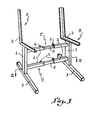
- the support shown in fig. 1 comprises two symmetrical elements A and B, assembled to one another by two adjustable crosspieces C arranged in superposition.
- Each element A or B comprises an upright 1, advantageously established in tubular form.
- the lower end of this upright 1 is provided with a horizontal base or base 2.
- the assembly 1-2 forms a base for a support 3 constituted by an angle iron whose vertical wing faces outward; each angle 3 is folded back to the square and it will be observed that the lower part of this square is fixed to the top of the upright 1, not horizontally, but with a slight obliquity, oriented from bottom to top of the rear forward.
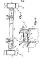
- Each of the two superimposed cross members C comprises a horizontal section 4 which extends transversely in overhang from the lateral face of the upright 1 of each element A and B; each profile or end piece 4 is fitted, in the vicinity of its free end, with a pressure screw 5 which, as illustrated in FIG. 2, is engaged through a thread formed in a puncture in the wall of said nozzle.
- Each cross member C is completed by an intermediate spacer 6, slidably introduced into the end pieces 5 facing the two elements A and B, and it is understood that the operation of the screws 5 allows this spacer 6 to be immobilized any desired axial position, the two elements A and B then being rigidly maintained at an appropriate spacing.
- the two spacers 6 have a tab 6a folded transversely in the corresponding outlet, so as to form a stop for the end of the screws 5. This arrangement prevents , when adjusting the length useful of each telescopic cross member C, the spacer 6 emerges inadvertently from one or the other of the two end pieces 4 which contain it.
- the user begins by loosening the four pressure screws 5, in order to release the spacers 6 from the crosspieces C. He places the enclosure on the ground with its base facing upwards and, as illustrated in fig. 3, it has against this base D the support with the feet 2 also arranged upwards; the two elements A and B are then brought close to each other until the angles or supports 3 come to bear against the horizontal edges corresponding to the rear of the base D. At this moment it suffices to maneuver the screws 5 to immobilize the elements A and B in the position obtained, and turn the enclosure over with the support to rest it on the ground.
- angles 3 ensure effective lateral retention of the acoustic enclosure, at the same time as they support the latter at the height and at the obliquity deemed to be the most favorable.
- the adjustment of the support is carried out very simply, the operation being capable of being carried out by the user himself, without requiring neither particular skill, nor tool.
- each cross member C In some cases it is possible to dispense with intermediate spacers 6, one of the end pieces 4 of each cross member C then being dimensioned to be telescopically inserted into the outlet of the opposite end piece.
- the number of crosspieces C can be any; in the same way, the base 1-2 of each element of the support can be shaped in any suitable way.
Landscapes
- Physics & Mathematics (AREA)
- Engineering & Computer Science (AREA)
- Acoustics & Sound (AREA)
- Signal Processing (AREA)
- Auxiliary Devices For Music (AREA)
- Purses, Travelling Bags, Baskets, Or Suitcases (AREA)
Applications Claiming Priority (2)
| Application Number | Priority Date | Filing Date | Title |
|---|---|---|---|
| FR8312303A FR2538663A1 (fr) | 1983-07-21 | 1983-07-21 | Support reglable pour enceinte acoustique |
| FR8312303 | 1983-07-21 |
Publications (3)
| Publication Number | Publication Date |
|---|---|
| EP0133142A2 true EP0133142A2 (de) | 1985-02-13 |
| EP0133142A3 EP0133142A3 (en) | 1985-03-13 |
| EP0133142B1 EP0133142B1 (de) | 1987-04-15 |
Family
ID=9291105
Family Applications (1)
| Application Number | Title | Priority Date | Filing Date |
|---|---|---|---|
| EP19840420122 Expired EP0133142B1 (de) | 1983-07-21 | 1984-07-06 | Anpassbare Stützvorrichtung für eine Lautsprecherbox |
Country Status (4)
| Country | Link |
|---|---|
| EP (1) | EP0133142B1 (de) |
| BR (1) | BR8403460A (de) |
| DE (1) | DE3463209D1 (de) |
| FR (1) | FR2538663A1 (de) |
Families Citing this family (1)
| Publication number | Priority date | Publication date | Assignee | Title |
|---|---|---|---|---|
| US4938447A (en) * | 1989-02-09 | 1990-07-03 | Schriner Michael J | Stand for a paper-discharging device |
Family Cites Families (4)
| Publication number | Priority date | Publication date | Assignee | Title |
|---|---|---|---|---|
| FR2382821A1 (fr) * | 1977-03-03 | 1978-09-29 | Mercuriale Specifique Acoustiq | Systeme d'enceintes acoustiques |
| DE2912632C2 (de) * | 1979-03-30 | 1981-02-19 | Magnat Electronik Gmbh & Co Kg, 5000 Koeln | Konsolartige Stützvorrichtung für eine Lautsprecherbox |
| DE2921898A1 (de) * | 1979-05-30 | 1980-12-11 | Bauermann & Soehne Gmbh | Staender fuer lautsprecherboxen |
| FR2462124A1 (fr) * | 1979-08-01 | 1981-02-13 | Vattier Claude | Table support a colonne centrale et deux niveaux |
-
1983
- 1983-07-21 FR FR8312303A patent/FR2538663A1/fr active Granted
-
1984
- 1984-07-06 EP EP19840420122 patent/EP0133142B1/de not_active Expired
- 1984-07-06 DE DE8484420122T patent/DE3463209D1/de not_active Expired
- 1984-07-11 BR BR8403460A patent/BR8403460A/pt unknown
Also Published As
| Publication number | Publication date |
|---|---|
| FR2538663B1 (de) | 1985-03-29 |
| EP0133142B1 (de) | 1987-04-15 |
| BR8403460A (pt) | 1985-06-25 |
| FR2538663A1 (fr) | 1984-06-29 |
| DE3463209D1 (en) | 1987-05-21 |
| EP0133142A3 (en) | 1985-03-13 |
Similar Documents
| Publication | Publication Date | Title |
|---|---|---|
| FR2617030A1 (fr) | Support jardinieres | |
| FR2738104A1 (fr) | Chassis de support, notamment pour appareillages electriques | |
| FR2510349A1 (fr) | Pots de fleurs ou analogues a accrochage automatique | |
| FR3073722A1 (fr) | Etagere de rangement/decoration | |
| EP0133142B1 (de) | Anpassbare Stützvorrichtung für eine Lautsprecherbox | |
| EP0165370A1 (de) | Hängevorrichtung | |
| FR2594309A1 (fr) | Meuble comportant une embase munie de roulettes | |
| EP2014204A1 (de) | Halterung für Blumenkästen, welche zur Aufnahme von zwei Blumenkästen übereinander geignet ist | |
| FR2767461A1 (fr) | Dispositif de module pour la realisation d'une gondole d'exposition a la vente d'objets dans un magasin | |
| EP0520864A1 (de) | Befestigungsvorrichtung für Verzierungselemente oder dergleichen auf allen Arten von Gondeln | |
| FR2658706A1 (fr) | Siege pliant. | |
| FR2600242A1 (fr) | Porte-pots ou porte-jardinieres expansibles pour balustrades | |
| EP0835974A1 (de) | Verbindungsorgan | |
| EP3400858A1 (de) | Befestigungsvorrichtung von heizkörperzubehörteilen | |
| EP1157635B1 (de) | Befestigungssystem an einer Säule für ein Trägerelement | |
| FR2490940A1 (fr) | Meuble de rangement | |
| CH184580A (fr) | Ensemble constitué par des bras amovibles et leurs moyens de fixation à une chaise. | |
| FR2663213A1 (fr) | Dispositif pour la suspension de tableaux, ou autres objets. | |
| FR2640860A1 (en) | Support for slat of bedstead and fixing nail | |
| FR2470277A1 (fr) | Dispositif d'assemblage d'elements surfaciques superposes et/ou juxtaposes pour meubles modulaires | |
| FR2459024A1 (fr) | Organe de fixation et de blocage de rayons a des murs | |
| FR2514808A1 (fr) | Dispositif de fixation d'un cordeau pour la construction | |
| FR2668911A1 (fr) | Cloison notamment pour stand d'exposition ainsi que les stands realises a l'aide de cette cloison. | |
| CH380320A (fr) | Fauteuil pour salle de spectacle | |
| FR2760615A1 (fr) | Distributeur polyvalent perfectionne de sacs ou sachets |
Legal Events
| Date | Code | Title | Description |
|---|---|---|---|
| PUAI | Public reference made under article 153(3) epc to a published international application that has entered the european phase |
Free format text: ORIGINAL CODE: 0009012 |
|
| PUAL | Search report despatched |
Free format text: ORIGINAL CODE: 0009013 |
|
| AK | Designated contracting states |
Designated state(s): BE CH DE GB LI NL |
|
| AK | Designated contracting states |
Designated state(s): BE CH DE GB LI NL |
|
| 17P | Request for examination filed |
Effective date: 19850511 |
|
| 17Q | First examination report despatched |
Effective date: 19860509 |
|
| GRAA | (expected) grant |
Free format text: ORIGINAL CODE: 0009210 |
|
| AK | Designated contracting states |
Kind code of ref document: B1 Designated state(s): BE CH DE GB LI NL |
|
| PG25 | Lapsed in a contracting state [announced via postgrant information from national office to epo] |
Ref country code: NL Effective date: 19870415 |
|
| REF | Corresponds to: |
Ref document number: 3463209 Country of ref document: DE Date of ref document: 19870521 |
|
| NLV1 | Nl: lapsed or annulled due to failure to fulfill the requirements of art. 29p and 29m of the patents act | ||
| PLBE | No opposition filed within time limit |
Free format text: ORIGINAL CODE: 0009261 |
|
| STAA | Information on the status of an ep patent application or granted ep patent |
Free format text: STATUS: NO OPPOSITION FILED WITHIN TIME LIMIT |
|
| 26N | No opposition filed | ||
| PG25 | Lapsed in a contracting state [announced via postgrant information from national office to epo] |
Ref country code: GB Effective date: 19880706 |
|
| PG25 | Lapsed in a contracting state [announced via postgrant information from national office to epo] |
Ref country code: LI Effective date: 19880731 Ref country code: CH Effective date: 19880731 Ref country code: BE Effective date: 19880731 |
|
| BERE | Be: lapsed |
Owner name: ERARD HENRI Effective date: 19880731 |
|
| GBPC | Gb: european patent ceased through non-payment of renewal fee | ||
| REG | Reference to a national code |
Ref country code: CH Ref legal event code: PL |
|
| PG25 | Lapsed in a contracting state [announced via postgrant information from national office to epo] |
Ref country code: DE Effective date: 19890401 |