EP0132380A2 - Adaptateur dans un système capteur/moniteur - Google Patents
Adaptateur dans un système capteur/moniteur Download PDFInfo
- Publication number
- EP0132380A2 EP0132380A2 EP84304918A EP84304918A EP0132380A2 EP 0132380 A2 EP0132380 A2 EP 0132380A2 EP 84304918 A EP84304918 A EP 84304918A EP 84304918 A EP84304918 A EP 84304918A EP 0132380 A2 EP0132380 A2 EP 0132380A2
- Authority
- EP
- European Patent Office
- Prior art keywords
- transducer
- monitor
- impedance
- monitoring
- signal
- Prior art date
- Legal status (The legal status is an assumption and is not a legal conclusion. Google has not performed a legal analysis and makes no representation as to the accuracy of the status listed.)
- Withdrawn
Links
- 238000012544 monitoring process Methods 0.000 claims abstract description 32
- 230000004962 physiological condition Effects 0.000 claims abstract description 7
- 238000006243 chemical reaction Methods 0.000 claims abstract description 6
- 241001465754 Metazoa Species 0.000 claims abstract description 5
- 230000001105 regulatory effect Effects 0.000 claims abstract description 4
- 230000001131 transforming effect Effects 0.000 claims abstract description 4
- 230000035945 sensitivity Effects 0.000 claims abstract description 3
- 230000009466 transformation Effects 0.000 claims abstract description 3
- 230000036772 blood pressure Effects 0.000 claims description 30
- 230000005284 excitation Effects 0.000 description 33
- 239000003990 capacitor Substances 0.000 description 16
- 230000002463 transducing effect Effects 0.000 description 5
- 239000008280 blood Substances 0.000 description 2
- 210000004369 blood Anatomy 0.000 description 2
- 238000001514 detection method Methods 0.000 description 2
- 238000010586 diagram Methods 0.000 description 2
- 230000000694 effects Effects 0.000 description 2
- 230000000712 assembly Effects 0.000 description 1
- 238000000429 assembly Methods 0.000 description 1
- 230000003139 buffering effect Effects 0.000 description 1
- 238000011109 contamination Methods 0.000 description 1
- 238000003745 diagnosis Methods 0.000 description 1
- 230000008030 elimination Effects 0.000 description 1
- 238000003379 elimination reaction Methods 0.000 description 1
- 238000005534 hematocrit Methods 0.000 description 1
- 230000001681 protective effect Effects 0.000 description 1
- 238000009966 trimming Methods 0.000 description 1
Images


Classifications
-
- A—HUMAN NECESSITIES
- A61—MEDICAL OR VETERINARY SCIENCE; HYGIENE
- A61B—DIAGNOSIS; SURGERY; IDENTIFICATION
- A61B5/00—Measuring for diagnostic purposes; Identification of persons
- A61B5/24—Detecting, measuring or recording bioelectric or biomagnetic signals of the body or parts thereof
- A61B5/30—Input circuits therefor
- A61B5/307—Input circuits therefor specially adapted for particular uses
-
- H—ELECTRICITY
- H03—ELECTRONIC CIRCUITRY
- H03F—AMPLIFIERS
- H03F3/00—Amplifiers with only discharge tubes or only semiconductor devices as amplifying elements
- H03F3/45—Differential amplifiers
- H03F3/45071—Differential amplifiers with semiconductor devices only
- H03F3/45076—Differential amplifiers with semiconductor devices only characterised by the way of implementation of the active amplifying circuit in the differential amplifier
- H03F3/45475—Differential amplifiers with semiconductor devices only characterised by the way of implementation of the active amplifying circuit in the differential amplifier using IC blocks as the active amplifying circuit
-
- A—HUMAN NECESSITIES
- A61—MEDICAL OR VETERINARY SCIENCE; HYGIENE
- A61B—DIAGNOSIS; SURGERY; IDENTIFICATION
- A61B5/00—Measuring for diagnostic purposes; Identification of persons
- A61B5/02—Detecting, measuring or recording pulse, heart rate, blood pressure or blood flow; Combined pulse/heart-rate/blood pressure determination; Evaluating a cardiovascular condition not otherwise provided for, e.g. using combinations of techniques provided for in this group with electrocardiography or electroauscultation; Heart catheters for measuring blood pressure
- A61B5/021—Measuring pressure in heart or blood vessels
-
- A—HUMAN NECESSITIES
- A61—MEDICAL OR VETERINARY SCIENCE; HYGIENE
- A61B—DIAGNOSIS; SURGERY; IDENTIFICATION
- A61B5/00—Measuring for diagnostic purposes; Identification of persons
- A61B5/24—Detecting, measuring or recording bioelectric or biomagnetic signals of the body or parts thereof
- A61B5/30—Input circuits therefor
-
- H—ELECTRICITY
- H03—ELECTRONIC CIRCUITRY
- H03F—AMPLIFIERS
- H03F3/00—Amplifiers with only discharge tubes or only semiconductor devices as amplifying elements
- H03F3/45—Differential amplifiers
- H03F3/45071—Differential amplifiers with semiconductor devices only
- H03F3/45479—Differential amplifiers with semiconductor devices only characterised by the way of common mode signal rejection
- H03F3/45928—Differential amplifiers with semiconductor devices only characterised by the way of common mode signal rejection using IC blocks as the active amplifying circuit
- H03F3/4595—Differential amplifiers with semiconductor devices only characterised by the way of common mode signal rejection using IC blocks as the active amplifying circuit by using feedforward means
- H03F3/45955—Measuring at the input circuit of the differential amplifier
- H03F3/45959—Controlling the input circuit of the differential amplifier
-
- A—HUMAN NECESSITIES
- A61—MEDICAL OR VETERINARY SCIENCE; HYGIENE
- A61B—DIAGNOSIS; SURGERY; IDENTIFICATION
- A61B2560/00—Constructional details of operational features of apparatus; Accessories for medical measuring apparatus
- A61B2560/04—Constructional details of apparatus
- A61B2560/0443—Modular apparatus
- A61B2560/045—Modular apparatus with a separable interface unit, e.g. for communication
Definitions
- This invention relates to systems for detecting physiological conditions, for example, blood-pressure, temperature, blood gas levels or haematocrit levels in humans or animals, for converting the detected condition into electrical signals, and for displaying, recording or otherwise monitoring these electrical signals promptly after detection.
- physiological conditions for example, blood-pressure, temperature, blood gas levels or haematocrit levels in humans or animals
- converting the detected condition into electrical signals and for displaying, recording or otherwise monitoring these electrical signals promptly after detection.
- Such systems include, for example, a blood-pressure transducer that is attached to the arterial or venous system of a human, a blood-pressure monitor that indicates blood-pressure and a connector between the transducer and the monitor.
- This invention provides a connector that is compatible with many different kinds of blood-pressure transducers and with many different kinds of blood-pressure monitors.
- our new connector permits linking a wide variety of transducers to a wide variety of monitors.
- this connector is compatible with many different kinds of blood pressure transducers, including disposable and reusable transducers, and with a wide variety of commercially available blood-pressure monitors.
- the connector can be adapted for use with monitors such as blood-pressure monitors that provide power to a transducer in the form of DC voltage, sine wave voltage, or pulsed voltage, for example, square wave voltage having a duty cycle of about 50%.
- the connector in preferred embodiment is then linked to one monitor or to a group of monitors whose power systems are compatible with the connector as adapted.
- the monitor/ connector combination can then be linked to the electrical output of a plurality of different kinds of transducers, thus avoiding the risks of contamination often arising when a transducer is decoupled from the lines leading into a patient's bloodstream:
- the universal connector means can accommodate a wide range of impedance levels in the signals from the transducers.
- the connector can accommodate signals from blood-pressure transducers having impedances in the range of about 50 to about 8,000 ohms.
- the connector can also accommodate and adjust to impedance levels appropriate for many different monitors.
- the connector can accommodate monitors that produce signals having an output impedance in the range of about 5 ohms to about one million ohms.
- our connector permits display and monitoring of signals from two or more different kinds of transducers on nonitors designed to display only one or two kinds of trans-3ucer signals.
- our connector permits adjusting the impedance level of a signal from a blood gas level transducer to a level appropriate for display on a monitor designed for displaying blood pressure.
- Our new connector can also link monitors with means for receiving and demodulating signals representing physiological conditions.
- Such receiving/demodulating means can be a radio frequency receiver/demodulator for signals from an RF modulator/ transmitter.
- Our new universal connector may also include means for adjusting offset or sensitivity of the signal from the blood-pressure transducing means, means for detecting absence of the transducing means, and means for detecting an open circuit between the transducing means and the monitoring means, when features of the monitor to be linked to the transducer require them.
- our new universal connector may also include means for converting power from the monitoring means to DC power where the power from the monitoring means, before conversion, is a sine wave or a pulsed voltage such as a square wave having a duty cycle of about 50%.
- our new connector may also include means for regulating the current from the monitoring means, and means for eliminating erroneous common-mode voltages and for imposing appropriate common-mode voltages compatible with a given monitoring means.
- our new universal connector includes two circuit assemblies mounted back-to-back.
- one circuit is designated the buffer-amplifier circuit; the other, the DC power supply circuit, current-regulating circuit, or common-mode eliminator circuit.
- the two circuits are linked by appropriate means (e.g., bus wire) and are selected to be compatible with the transducer and monitor in our system.
- Fig. 1 provides a block diagram of our new system, including blood-pressure transducer 1 linked to blood-pressure monitor 7 by cables 2 and 6 and by our new universal connector 3.
- Connector 3 includes buffer-amplifier circuit board 4 linked to circuit board 5, which includes either a DC power supply circuit, a current-regulating circuit, or a common-mode elimination circuit.
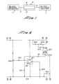
- Fig. 2 provides a detailed schematic of the preferred embodiment of our buffer-amplifier circuit.
- This circuit draws power from the blood-pressure monitoring means, and utilizes that power directly where the power is DC.
- Another circuit is used to modify and adapt the power if the power is sine wave or pulsed (see Fig. 3).
- the left side of the buffer-amplifier circuit is linked to the blood-pressure transducing means; the right side, to the blood-pressure monitoring means.
- positive and negative excitation pass from the monitoring means on paths 110 and 111 through contacts 6 and 12 to the other circuit in the connector means (described below) and return to the buffer-amplifier circuit, adapted as necessary, through contact pairs 5/11, 2/4, and 1/3.
- the excitation current then flows to the transducer along paths 112 and 113.
- Signals representative of blood pressure pass from the transducer means on paths 114 and 115 with their negative side on path 115, and their positive side, on path 114. These signals pass through protective resistors 116 and 117 to input rails 118 and 119 on amplifiers 120 and 121, respectively.
- the diffential gain through amplifiers 120 and 121 is approximately one unless gain-setting resistors 122-124 are present. Normally, only an impedance level conversion takes place as the signals undergo buffering through amplifiers 120 and 121.
- a common transducer output impedance is between 300 and 5,000 ohms; amplifier output impedance is in the range of about 1 to about 5 ohms.
- the buffer-amplifier circuit includes means for removing offset errors in the signal voltage to the monitoring means. Adjustment of potentiometers 129 (on amplifier 121) and 130 (on amplifier 120) permit setting the output voltages of these amplifiers at the same level as their input voltages.
- Gain-setting resistors 122, 123 and 124 permit accurate gain tailoring.
- Resistors 131, 132 and 133 permit adjustment of amplifier bandwidth when programmable amplifiers are used.
- the buffer-amplifier circuit of Fig. 2 also includes means for detecting a missing transducer or an open lead.
- Two resistor dividers are used to develop reference voltages.
- Resistors 134, 135 and 136 develop two voltages referenced to the magnitude of the transducer excitation voltage.
- the voltage at juncture 138 of resistors 134, 135 and 137 is more than half the instantaneous excitation voltage; the voltage at junction 139 of resistors 135, 136 and 140 is less than half of the excitation voltage, and common-mode voltage from the transducer is about 50% of excitation voltage. Accordingly, the voltage at junction 141 of resistors 142 and 143 is about half the excitation voltage.
- the detection circuitry In normal operation, the detection circuitry has little effect upon signal paths because resistors 137 and.140 are large compared with transducer output resistance, and because diodes 143-148 are reverse biased. If no transducer is present, however, resistors 137 and 140 are small compared to the input impedance of amplifiers 120 and 121. The resulting large reverse polarity signal at the blood-pressure monitor indicates the absence of a transducer.
- the reverse reference voltage operating through resistor 137 and 140 has no impact on the signal because of the low output impedance of the transducer.
- the negative excitation line is open, signals on paths 114 and 115 will be pulled toward the positive excitation voltage by current through the transducer. As the signals become more positive, diode 147 becomes forward biased. The signal at the inboard side of resistor 116 is clamped at one diode drop above the output of amplifier 149. The signal at resistor 117 continues to rise, almost to the level of the positive excitation voltage. The resulting large negative signal appearing at the monitor indicates the error. The same occurs where the positive excitation line is open, and the negative line is connected. If both the positive and negative lines are open, and both paths 114 and 115 are connected to amplifiers 120 and 121, a much smaller negative signal will appear at the monitoring means.
- Fig. 3 provides a detailed schematic of a DC power supply circuit. This circuit performs four functions.
- output resistors 201 and 202 are matched to the impedance requirement of the monitoring means.
- Output signals from a buffer-amplifier circuit of Fig. 1 appear at contacts 7 and 9 and return to the buffer-amplifier circuit through contacts 8 and 10.
- resistor network 203, 204 and 205 provides this function.
- a calibration signal passes through the buffer-amplifier circuit through contact 13.
- this circuit provides sine wave phase correction through the network including potentiometer 206 and capacitors 207 and 208. Unbuffered signals from the transducer pass to sine wave phase correction through contacts 14 and 15.
- the fourth and most important function of the circuit in Fig. 3 is conversion of sine wave or pulsed excitation signals to DC voltage suitable for operating the buffer-amplifier circuit. To accommodate the various types of excitation signals, the components in the circuit are varied and tailored as needed.
- this circuit includes capacitors 209, 210, 213 and 214; diodes 211, 212, 215 and 216; resistor 217; and jumper wire 218. Omitted are jumper wires 219 and 220 and resistors 221 and 222.
- the negative excitation signal from the monitoring means is used as a reference, and is connected to junction 223 via jumper wire 218.
- the upper and lower halves of this circuit then function as two separate converters, with each functioning as a voltage doubler.
- the upper half produces a positive voltage; the lower half a negative voltage, with respect to the negative excitation signal.
- Capacitor values are appropriate to produce low-ripple DC voltage.
- the upper half of the circuit functions as follows. Assume that the excitation voltage is a sine wave from a transformer. Assume that the negative excitation voltage from the monitoring means is a reference voltage, and that all voltages in the power supply are defined with respect to this reference. Total excitation voltage is applied to each half of the circuit independently. As the negative half-cycle of the positive excitation signal from the monitoring means is applied to capacitor 213, current flows from the reference through diode 215 to charge the positive side of the capacitor 213 to approximately reference potential. The negative side of capacitor 213 is charged with a negative peak of the positive excitation signal. Therefore, capacitor 213 holds a voltage approximating the peak excitation voltage.
- capacitor 213 As the positive excitation sine wave goes from a negative to a positive peak with respect to the reference, the voltage on both sides of capacitor 213 changes by the same amount.
- the negative side of capacitor 213 changes from negative excitation peak to positive excitation peak.
- the positive side changes from the reference voltage to twice the positive excitation peak less the diode drop.
- the voltage on the positive side of capacitor 213 also causes diode 211 to become forward biased. Current then flows into the positive side of capacitor 209.
- Capacitor 209 is charged to a voltage that approximates double the positive excitation voltage peak minus two diode drops. Operation of the other half of the supply is the same, but polarity is reversed.
- the circuitry in Fig. 3 is configured as follows. Capacitors 209 and 210, and diodes 211 and 212 remain in circuit with resistors 221 and 222 and jumper wires 220 and 219. Capacitors 213 and 214, diodes 215 and 216, resistor 217 and jumper wire 218 are omitted. With symmetrical waveforms, the excitation voltages is applied across both halves of the circuit in series. Where no pulse is present, both diodes 211 and 212 are back biased. When simultaneous pulses appear, these diodes conduct, and capacitors 209 and 210 receive charging current. The final voltage developed in capacitors 209 and 210 in series is approximately twice the pulse amplitude minus the drops across the diodes 211 and 212.
- Excitation voltages passes from the circuitry of Fig. 2 to contacts 6 and 12, and returns to the buffer-amplifier circuit unaltered through contacts 1 and 3. DC power returns to the buffer-amplifer circuit through contacts 2, 4, 5 and 11.
- Fig. 4 illustrates the preferred embodiment of the current-regulating circuit that provides three functions.
- output resistors 301 and 302 serve the same functions as resistors 201 and 202 in the DC power circuit illustrated in Fig. 3.
- calibration resistors 303, 304 and 305 serve the same function as calibration resistors 203, 204 and 205 in the circuitry of Fig. 3.
- this circuit provides current regulation.
- the total excitation load current, on leads 6 and 12, passes through resistor 306.
- Amplifier 307 samples the current at resistor 306, and varies amplifier output current through resistor 308, thus regulating current through resistor 306.
- Potentiometer 309 and resistor network 310/311 permit current trimming.
- the reference voltage for amplifier 307 on negative rail 312 is the excitation voltage on path 313 applied through resistor 314.
- Fig. 5 provides a detailed schematic of a preferred embodiment for the common-mode eliminator circuit.
- This circuit has three functions. First, resistors 401 and 402 are matched to the impedance requirements of the monitor, and function as resistor 301/302 and 201/202 of Figs. 3 and 4 do. Secondly, calibration resistors 403, 404 and 405 serve the same functions as the calibration resistors illustrated in Figs. 3 and 4.
- the most important function of the circuitry in Fig. 5 is to remove an erroneous common-mode voltage from the transducer signal and substitute a proper common-mode voltage.
- Amplifier 406 and its related components provide the desired common-mode voltage, Potentiometer 407 is adjusted to obtain a voltage at the output 408 of amplifier 406 equal to half the excitation voltage.
- This developed common-mode voltage then serves as the reference voltage for the differential amplifier circuit including amplifiers 409 and 410.
- Buffered transducer signals pass from the buffer-amplifier circuit of Fig. 2 through contacts 7 and 9.
- the signal through contact 7 is applied to input resistors 410 and 411 along paths 412 and 413, respectively.
- the signal through contact 9 is applied to input resistors 417 and 418 along paths 419 and 420, respectively.
- Corrected signals at outputs 421 and 414 pass through output resistors 401 and 402, respectively, and then through contacts 8 and 10 to the buffer-amplifier circuit shown in F ig. 2.
- Potentiometers 415 and 416 permit adjustment of the gain through amplifiers 40 and 410. Precise gain matching between two sides of the amplifiers is essential to maintain good common-mode rejection.
Landscapes
- Health & Medical Sciences (AREA)
- Life Sciences & Earth Sciences (AREA)
- Engineering & Computer Science (AREA)
- Molecular Biology (AREA)
- Animal Behavior & Ethology (AREA)
- Biophysics (AREA)
- Pathology (AREA)
- Biomedical Technology (AREA)
- Heart & Thoracic Surgery (AREA)
- Medical Informatics (AREA)
- Veterinary Medicine (AREA)
- Surgery (AREA)
- Physics & Mathematics (AREA)
- General Health & Medical Sciences (AREA)
- Public Health (AREA)
- Power Engineering (AREA)
- Cardiology (AREA)
- Vascular Medicine (AREA)
- Physiology (AREA)
- Measuring Pulse, Heart Rate, Blood Pressure Or Blood Flow (AREA)
- Measuring And Recording Apparatus For Diagnosis (AREA)
- External Artificial Organs (AREA)
- Amplifiers (AREA)
Applications Claiming Priority (4)
| Application Number | Priority Date | Filing Date | Title |
|---|---|---|---|
| US51532883A | 1983-07-19 | 1983-07-19 | |
| US515328 | 1983-07-19 | ||
| US62989284A | 1984-07-16 | 1984-07-16 | |
| US629892 | 1984-07-16 |
Publications (2)
| Publication Number | Publication Date |
|---|---|
| EP0132380A2 true EP0132380A2 (fr) | 1985-01-30 |
| EP0132380A3 EP0132380A3 (fr) | 1987-09-09 |
Family
ID=27058459
Family Applications (1)
| Application Number | Title | Priority Date | Filing Date |
|---|---|---|---|
| EP84304918A Withdrawn EP0132380A3 (fr) | 1983-07-19 | 1984-07-19 | Adaptateur dans un système capteur/moniteur |
Country Status (3)
| Country | Link |
|---|---|
| EP (1) | EP0132380A3 (fr) |
| JP (1) | JPS6036033A (fr) |
| CA (1) | CA1236708A (fr) |
Cited By (1)
| Publication number | Priority date | Publication date | Assignee | Title |
|---|---|---|---|---|
| WO1997014358A1 (fr) * | 1995-10-20 | 1997-04-24 | Aspect Medical Systems, Inc. | Dispositif connecteur d'electrodes |
Citations (2)
| Publication number | Priority date | Publication date | Assignee | Title |
|---|---|---|---|---|
| FR2275183A1 (fr) * | 1974-06-21 | 1976-01-16 | Siemens Ag | Montage pour le traitement de signaux de mesure physiologiques |
| US4173221A (en) * | 1977-04-15 | 1979-11-06 | Wallace Rogozinski | EKG cable monitoring system |
Family Cites Families (1)
| Publication number | Priority date | Publication date | Assignee | Title |
|---|---|---|---|---|
| JPS5117531A (ja) * | 1974-08-02 | 1976-02-12 | Hitachi Ltd | Henryuki |
-
1984
- 1984-07-19 EP EP84304918A patent/EP0132380A3/fr not_active Withdrawn
- 1984-07-19 CA CA000459243A patent/CA1236708A/fr not_active Expired
- 1984-07-19 JP JP59151114A patent/JPS6036033A/ja active Granted
Patent Citations (2)
| Publication number | Priority date | Publication date | Assignee | Title |
|---|---|---|---|---|
| FR2275183A1 (fr) * | 1974-06-21 | 1976-01-16 | Siemens Ag | Montage pour le traitement de signaux de mesure physiologiques |
| US4173221A (en) * | 1977-04-15 | 1979-11-06 | Wallace Rogozinski | EKG cable monitoring system |
Non-Patent Citations (2)
| Title |
|---|
| IEEE TRANSACTIONS ON BIO-MEDICAL ENGINEERING, vol. BME-18, no. 1, January 1971, pages 60-65, New York, US; R.M. GARDNER et al.: "Instrumentation for computerized heart catheterization" * |
| MEDICAL & BIOLOGICAL ENGINEERING & COMPUTING, vol. 18, no. 2, March 1980, pages 167-178, Stevenage, GB; G.D. MINTZ et al.: "Specification and design of an evoked-response data-acquisition system" * |
Cited By (3)
| Publication number | Priority date | Publication date | Assignee | Title |
|---|---|---|---|---|
| WO1997014358A1 (fr) * | 1995-10-20 | 1997-04-24 | Aspect Medical Systems, Inc. | Dispositif connecteur d'electrodes |
| US5813404A (en) * | 1995-10-20 | 1998-09-29 | Aspect Medical Systems, Inc. | Electrode connector system |
| US6236874B1 (en) | 1995-10-20 | 2001-05-22 | Aspect Medical Systems, Inc. | Electrode connector system |
Also Published As
| Publication number | Publication date |
|---|---|
| EP0132380A3 (fr) | 1987-09-09 |
| JPS6036033A (ja) | 1985-02-25 |
| CA1236708A (fr) | 1988-05-17 |
| JPH0553493B2 (fr) | 1993-08-10 |
Similar Documents
| Publication | Publication Date | Title |
|---|---|---|
| US5193547A (en) | Universal connector means for transducer/monitor systems | |
| US4695955A (en) | Electronic device providing a universal interface between sensors and an acquisition and processing unit of the signals originating from said sensors | |
| US4235242A (en) | Electronic circuit permitting simultaneous use of stimulating and monitoring equipment | |
| US5427111A (en) | Receiver for differential signals with means for adjusting a floating ground state | |
| US8086300B2 (en) | ECG electrode contact quality measurement system | |
| US5568815A (en) | Self-powered interface circuit for use with a transducer sensor | |
| Winter et al. | Reduction of interference due to common mode voltage in biopotential amplifiers | |
| Spinelli et al. | AC-coupled front-end for biopotential measurements | |
| EP1411830B1 (fr) | Systeme et procede de mesure d'impedance bioelectrique en presence d'interferences | |
| EP0800787B1 (fr) | Dispositif de contrôle d'électrodes de mesure destinées à la réception de signaux physiologiques | |
| US4993423A (en) | Method and apparatus for differential lead impedance comparison | |
| EP0581073A2 (fr) | Circuit integré à application specifique pour la surveillance physiologique | |
| US2660165A (en) | Electrical calibration system | |
| US5634470A (en) | System and method for monitoring and controlling the temperature of a catheter-mounted heater | |
| US20190029548A1 (en) | Impedance bootstrap circuit for an interface of a monitoring device | |
| WO1998002087A1 (fr) | Oxymetre convertissant un signal direct en signal numerique | |
| US5788644A (en) | Automatic lead switching for ECG monitor | |
| EP1611845A1 (fr) | Système pour la détermination de l'existence d'une connexion d'une électrode | |
| US4243044A (en) | Coupling circuit with driven guard | |
| EP0199219A2 (fr) | Amplificateur électro-encéphalographique à bande étroite | |
| US20020183634A1 (en) | Monitoring of patient's electrical characteristics | |
| EP0778002B1 (fr) | Système destiné à la surveillance cardiaque présentant une gamme réduite d'acquisition de signaux | |
| EP0132380A2 (fr) | Adaptateur dans un système capteur/moniteur | |
| CN116271532A (zh) | 经颅电刺激装置 | |
| EP0765632A2 (fr) | Procédé et appareil pour la surveillance de la respiration |
Legal Events
| Date | Code | Title | Description |
|---|---|---|---|
| PUAI | Public reference made under article 153(3) epc to a published international application that has entered the european phase |
Free format text: ORIGINAL CODE: 0009012 |
|
| AK | Designated contracting states |
Designated state(s): DE FR GB |
|
| PUAL | Search report despatched |
Free format text: ORIGINAL CODE: 0009013 |
|
| AK | Designated contracting states |
Kind code of ref document: A3 Designated state(s): DE FR GB |
|
| RAP1 | Party data changed (applicant data changed or rights of an application transferred) |
Owner name: BAXTER TRAVENOL LABORATORIES, INC. |
|
| 17P | Request for examination filed |
Effective date: 19880104 |
|
| RAP1 | Party data changed (applicant data changed or rights of an application transferred) |
Owner name: BAXTER INTERNATIONAL INC. (A DELAWARE CORPORATION) |
|
| 17Q | First examination report despatched |
Effective date: 19890608 |
|
| STAA | Information on the status of an ep patent application or granted ep patent |
Free format text: STATUS: THE APPLICATION IS DEEMED TO BE WITHDRAWN |
|
| 18D | Application deemed to be withdrawn |
Effective date: 19900714 |
|
| RIN1 | Information on inventor provided before grant (corrected) |
Inventor name: EVANS, GEORGE D., II Inventor name: NORMAN, JACOB J. Inventor name: PHILIPS, HOWARD DON |