EP0778002B1 - Système destiné à la surveillance cardiaque présentant une gamme réduite d'acquisition de signaux - Google Patents
Système destiné à la surveillance cardiaque présentant une gamme réduite d'acquisition de signaux Download PDFInfo
- Publication number
- EP0778002B1 EP0778002B1 EP96307995A EP96307995A EP0778002B1 EP 0778002 B1 EP0778002 B1 EP 0778002B1 EP 96307995 A EP96307995 A EP 96307995A EP 96307995 A EP96307995 A EP 96307995A EP 0778002 B1 EP0778002 B1 EP 0778002B1
- Authority
- EP
- European Patent Office
- Prior art keywords
- signal
- electrodes
- offset adjustment
- signal acquisition
- electrode
- Prior art date
- Legal status (The legal status is an assumption and is not a legal conclusion. Google has not performed a legal analysis and makes no representation as to the accuracy of the status listed.)
- Expired - Lifetime
Links
Images

Classifications
-
- A—HUMAN NECESSITIES
- A61—MEDICAL OR VETERINARY SCIENCE; HYGIENE
- A61B—DIAGNOSIS; SURGERY; IDENTIFICATION
- A61B5/00—Measuring for diagnostic purposes; Identification of persons
- A61B5/24—Detecting, measuring or recording bioelectric or biomagnetic signals of the body or parts thereof
- A61B5/25—Bioelectric electrodes therefor
- A61B5/279—Bioelectric electrodes therefor specially adapted for particular uses
- A61B5/28—Bioelectric electrodes therefor specially adapted for particular uses for electrocardiography [ECG]
-
- A—HUMAN NECESSITIES
- A61—MEDICAL OR VETERINARY SCIENCE; HYGIENE
- A61B—DIAGNOSIS; SURGERY; IDENTIFICATION
- A61B5/00—Measuring for diagnostic purposes; Identification of persons
- A61B5/24—Detecting, measuring or recording bioelectric or biomagnetic signals of the body or parts thereof
- A61B5/30—Input circuits therefor
- A61B5/307—Input circuits therefor specially adapted for particular uses
- A61B5/308—Input circuits therefor specially adapted for particular uses for electrocardiography [ECG]
Definitions
- This invention relates to heart monitoring systems, such as electrocardiograph systems, for measuring heart activity in a human patient.
- An electrocardiograph (ECG) system monitors heart activity in a human patient.
- the ECG system applies small conductive pads or “electrodes” to specific locations on the human patient.
- Each electrode has an adhesive patch and a conductive member (which might be one in the same) that is placed on the patient's skin. These electrodes detect electrical impulses generated by the heart during each beat.
- Each heart beat generates a waveform that consists of three identifiable wave complexes referred to as the P, QRS, and T wave complexes.
- a conventional 12-lead resting ECG is conducted using ten electrodes.
- An electrode is adhered to each of the four limbs of the human patient--left arm, right arm, left leg, and right leg--and to six anatomically-prescribed locations across the chest and left side of the human patient.
- the electrodes In response to detection of the electrical impulses from the heart, the electrodes produce electrical signals indicative of the heart activity. These electrical signals have small magnitudes on the order of 1 mV, and are commonly resolved by signal processes down to about 5 ⁇ V. The electrical signals are different from one another by virtue of the different physical locations of the electrodes about the patient.
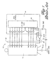
- Fig. 1 shows a diagrammatic representation of a conventional ECG system 10 having ten electrodes V1-V6, RA, LA, LL, and RL connected to a human patient 12.
- the electrodes are connected to an ECG device 14 via conductors 16.
- ECG device 14 detects the electrical signals generated by the electrodes and performs various signal processing and computational operations to convert the raw electrical signals into meaningful information that can be displayed or printed out for review by a physician.
- ECG device 14 can produce two sets of ECG leads: limb leads and chest leads.
- V1 V1 - (RA+LA+LL)/3
- Lead V2 V2 - (RA+LA+LL)/3
- Lead V3 V3 - (RA+LA+LL)/3
- Lead V4 V4 - (RA+LA+LL)/3
- Lead V5 V5 - (RA+LA+LL)/3
- Lead V6 V6 - (RA+LA+LL)/3.
- each of these twelve ECG leads of a conventional 12-lead ECG test concerns input from only three of the four limb electrodes: the right arm electrode RA, the left arm electrode LA, and the left leg electrode LL.
- the right leg electrode RL is not used in deriving a multichannel ECG recording. Part of this is due to the RL electrode being located farthest from the heart in comparison to the other nine electrodes.
- the right leg electrode RL is used, however, to help reduce common-mode interference that appears between the signal leads and a common reference plane. As illustrated in Fig. 1, it is common for the patient to have an electric potential V P-E relative to a true electrical earth ground, while the ECG device has a relative or floating ground ECG GND that is at a different electric potential V E-ECG relative to true earth ground. Typically, ECG device 14 is configured so that its own ground ECG GND tries to approximate true earth ground, thereby leaving a difference in potential between the patient 12 and ECG device 14. These different potentials cause common-mode noise voltage in the electrode signals carried by conductors 16 which appears equally and in phase from each electrode/conductor relative to ground.
- the RL electrode is driven in such a way that the patient-to-earth ground voltage potential V P-E and the ECG device-to-earth ground potential V E-ECG are approximately equal, thereby substantially removing the common mode interference before the ECG even conducts the lead computations.
- the RL electrode is based upon the average of the other three limb electrodes RA, LL, and LA.
- An operational amplifier 22 provides a correcting current based upon a difference between the average voltage from these three limbs and the ECG GND.
- Performance standards e.g., ANSI
- ANSI ANSI
- ANSI ANSI
- ANSI ANSI
- a designer conducts a test where one conductor is driven to +300 mV relative to all other conductors and a reading is taken to detect electrical signals. Then that same conductor is driven to -300 mV relative to all other conductors and another reading is taken. This action is repeated for each of the conductors. The system passes if signals can be detected over the entire ⁇ 300 mV range.
- ECG device 14 typically has an amplifying subsystem 18 which amplifies the analog signals generated by the electrodes and an analog-to-digital (A/D) converter 20 which converts the amplified analog signals into digital values that are resolved down to approximately 5 ⁇ V.
- A/D analog-to-digital
- a 17-bit A/D converter is used to account for the 120,000 resolvable increments (i.e., 600 mV/5 ⁇ V).
- Other techniques might alternatively be used to detect signals within the 600 mV range, such as a hardware high-pass pole.
- US 4,890,630 discloses a bio-electric noise cancellation system. There is also disclosed a method for the bio-electric monitoring system to cancel noise on the body of a patient.
- the system includes a plurality of monitoring electrodes which are connected to a signal averager. The signals produced by the monitoring electrodes are averaged and then amplified and supplied to a driving electrode which supplies a noise correction signal to the body of the patient.
- This invention provides a heart monitoring system as defined in the appendent claims.
- the system continuously and dynamically drives the ECG GND to a value based upon a selected voltage level (such as the minimum or maximum voltage level) output from one or more of the electrodes, as opposed to a fixed combination of electrode signals.
- a voltage level based on an electrode output rather than ECG GND, the dynamic signal acquisition range is reduced by one-half to approximately 300 mV from the traditional 600 mV plus range.
- less complex and less expensive acquisition circuitry such as a 16-bit A/D converter, can be used for the signal conversion process.
- an ECG system includes a plurality of electrodes adapted to be connected to a human patient.
- these electrodes consist of the six electrodes V1-V6, the right arm electrode RA, the left arm electrode LA, the left leg electrode LL, and the right leg electrode RL.
- the electrodes generate electrical signals indicative of heart activity within the patient.
- the ECG system also includes a plurality of conductors connected to corresponding electrodes and a signal acquisition system connected to the conductors.
- the signal acquisition system has a signal acquisition range and detects the electrical signals with voltage levels that fall within the signal acquisition range.
- the ECG system also has an offset adjustment system operatively coupled to the signal acquisition system.
- the offset adjustment system identifies a selected voltage level (such as a maximum or minimum voltage level) of at least one of the electrical signals generated by an associated electrode and manipulates that voltage level to produce an offset adjustment signal.
- This offset adjustment signal is used to bring voltage levels of all of the electrical signals produced by the electrodes within the signal acquisition range of the signal acquisition system.
- the ECG system further includes a potential adjusting feedback circuit coupled between the offset adjustment system and one of the electrodes (such as the right leg electrode RL) to supply a potential to that electrode.
- the potential moves toward the offset adjustment signal to offset the electric potentials of the human patient by an equal amount. This offset has the effect of moving the range of electrode voltages into the range of the signal acquisition system and yields a maximum signal acquisition range of approximately 300 mV.
- ECG GND ECG GND
- the common mode voltage of the ECG GND (relative to earth ground) is driven to track the common mode voltage of the patient (relative to earth ground) as described in the Background of the Invention section. From the viewpoint of the ECG GND, the net effect is that the common mode voltage of the patient can be controlled.
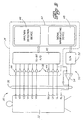
- FIG. 2 shows a heart monitoring system implemented as an ECG system 30 according to one aspect of this invention.
- ECG system 30 includes ten electrodes for conducting a 12-lead ECG test on a human patient 32.
- the electrodes are positioned at well known anatomically-selected locations on human patient 32. These electrodes consist of six ventricular electrodes V1-V6, a right arm electrode RA, a left arm electrode LA, a left leg electrode LL, and a right leg electrode RL, as is common in a 12-lead ECG test.
- the electrodes measure heart activity within patient 32 and generate electrical signals indicative of such heart activity.
- ECG device 34 detects and processes the signals generated by the electrodes.
- ECG device 34 calculates numerical results which are informative to a physician or other health care provider.
- One suitable ECG device 34 is the commercially available PageWriter XLi cardiograph produced by Hewlett-Packard Company, modified to include a signal acquisition system, an offset adjustment system, and feedback circuitry, which is described below in more detail with reference to Fig. 2.
- This cardiograph computes more than 800 numerical results, collectively known as the "measurement matrix", which are stored in a measurement table.
- the waveforms captured by the electrodes and these numerical computations are provided to the health care provider via a monitor display or an ECG printout.
- the techniques for detecting and processing ECG waveforms are known and thus are not described in detail herein.
- ECG device 34 is shown as comprising a signal acquisition system having an amplifying subsystem 38 and an A/D converter 40.
- the ECG device 34 is also shown as having an offset adjustment system 42.
- the other conventional components of ECG device 34 are not shown to simplify discussion of the present invention.
- amplifying subsystem 38 comprises individual amplifiers 44 resident at ECG device 34 to amplify the electrical signals generated by the electrodes. In other implementations, however, amplifying subsystem 38 can be located remote from the ECG device 34 in its own housing near the patient, or at the individual electrodes themselves.
- Amplifying subsystem 38 has a set of inputs electrically coupled to nine of the electrodes via associated conductors 36.
- the amplifying subsystem 38 also has a set of corresponding outputs to output amplified signals to A/D converter 40.
- the electrical analog signals produced by electrodes V1-V6, RA, LA and LL are carried via conductors 36 to amplifying subsystem 38, where they are amplified.
- the amplified signals are then passed to A/D converter 40 which converts the analog signals to digital values that can be processed and used for computational derivations.
- the electrical signals generated by the electrodes and then amplified have associated voltage levels.
- the signal acquisition system has a signal acquisition range that is less than conventional systems, and is preferably only approximately 300 mV.
- the signal acquisition system is capable of detecting and converting electrical signals with voltage levels that fall within the 300 mV signal acquisition range.
- the A/D converter 40 of the signal acquisition system is preferably a conventional 16-bit A/D converter.
- Offset adjustment system 42 is operatively coupled to A/D converter 40 via a multi-bit bus.
- the offset adjustment system identifies a selected voltage level of at least one of the electrical signals and manipulates that voltage level to produce an offset adjustment signal.
- This offset adjustment signal is used to bring voltage levels of all of the electrical signals produced by the electrodes within the signal acquisition range of the signal acquisition system.
- the offset adjustment system 42 includes a maximum/minimum voltage level detection device 46 which identifies the maximum or minimum voltage level of the nine electrical signals output from the electrodes V1-V6, RA, LA, and LL. More specifically, max/min detection device 46 detects the maximum or minimum digital value that is output from A/D converter 40. The maximum or minimum values are detected to help generate a reference ceiling or floor voltage to which all other signals are relative. This is useful for narrowing the dynamic signal acquisition range to approximately 300 mV, as will become more clear from the continuing discussion. Preferably, max/min detection device 46 is configured to detect either the maximum voltage level or the minimum voltage level.
- the max/min detection device is shown, however, as a maximum/minimum detector to demonstrate that it can be optimized to detect either extreme. Furthermore, it is noted that the device can be configured to detect some other selected voltage level, such as the mid-point between the maximum and minimum extremes.
- the offset adjustment system 42 further includes a signal manipulating device 48 which computes the offset adjustment signal as a function of the maximum or minimum voltage level detected by the max/min detection device 46.
- the signal manipulating device 48 receives a combination of (1) the maximum or minimum voltage level from the max/min detection device 46 and (2) a voltage level of another one of the electrical signals from the electrodes. From these two inputs, the signal manipulating device 48 produces an offset adjustment signal as a function of both.
- the signal manipulating device 48 computes an offset adjustment signal equal to a difference between the maximum or minimum voltage level and at least one other voltage level, such as the voltage level produced by the left leg LL electrode, plus a desired offset voltage to center the leadwire voltages within a signal acquisition range.
- the offset adjustment system 42 is implemented as a processor, such as microprocessor or a specially designed ASIC.
- the max/min detection device 46 and the signal manipulating device 48 are firmware-based components programmed into the processor to perform the above described functions.
- the offset adjustment system 42, max min detection device 46, and the signal manipulating device 48 can alternatively be implemented in discrete hardware components.
- ECG system 30 also includes a potential adjusting feedback circuit 50 which effectively adjusts the electric potential on human patient 32 toward a desired reference potential.
- Potential adjusting feedback circuit 50 is electrically coupled between the offset adjustment system 42 and one of the electrodes to supply a correcting current to the patient.
- feedback circuit 50 is coupled to the right leg electrode RL, although other coupling configurations can be employed.
- the correcting current is derived from a difference between the offset adjustment signal and one or more electrode voltages (such as the voltage level for electrode LL) to drive the range of electric potentials of the human patient to within a predetermined acquisition range of the amplifier and A/D converter.
- the potential adjusting feedback circuit 50 is preferably resident at ECG device 34.
- potential adjusting feedback circuit 50 has a digital-to-analog (D/A) converter 52 to convert the offset adjustment signal from the offset adjustment system 42 back into an electrical analog signal.
- Feedback circuit 50 further includes an inverting integrating operational amplifier (op amp) 54 coupled between the D/A converter and the right leg electrode RL.
- op amp inverting integrating operational amplifier
- op amp 54 has a first or negative input coupled to the amplified output that corresponds to the left leg electrode LL, a second or positive input coupled to D/A converter 52, and an output coupled to the right leg electrode RL.
- more than one amplified output can be collectively input to the negative terminal of op amp 54.
- a resistance path can be provided between all three appendage electrodes RA, LA, and LL so that the negative input of op amp 54 receives a voltage equal to the average of the voltages from electrodes RA, LA, and LL.
- the illustrated embodiment only shows a single amplified output coupled to the negative terminal of op amp 54.
- Feedback op amp 54 derives an electrical analog signal based upon a differential between the amplified signal from electrode LL and the analog signal from D/A converter 52.
- the feedback loop causes the voltage on the left leg electrode LL to approximate the voltage delivered to the positive terminal of op amp 54 from D/A 52.
- the negative feedback implementation drives the voltages at the positive and negative inputs to the op amp 54 to be approximately equal. This occurs because as the voltage from electrode LL goes higher than the voltage signal output by the D/A 52, the op amp 54 will output a negative differential voltage to the right leg electrode.
- the differential signal output by op amp 54 offsets the electric potentials of human patient 32 by the same amount, thereby lowering the voltage of left leg electrode LL back toward the D/A output voltage from D/A 52.
- Generation of a proper offset adjustment signal from the signal manipulating device 48, which is converted to the analog voltage applied at the positive terminal of the op amp 54, can thereby control the electric potentials of all leadwires to converge within a narrower acquisition range of the signal measurement system.
- the signal acquisition range is 0 to 327.68 mV (where the upper limit of 327.68 mV is equal to the 5 ⁇ V increments times 2 16 ).
- the offset adjustment signal is set to a value that converts to an arbitrary voltage at the positive input terminal at op amp 54. For example, suppose this arbitrary voltage is 164 mV, which is approximately the mid-point in the signal acquisition range. Due to the negative feedback configuration of circuit 50, the voltage at the left leg electrode LL will approximate the voltage applied to the positive terminal, and thus, will also be at 164 mV.
- the offset adjustment system 42 observes the values from the nine electrodes. According to conventional techniques for hooking up the electrodes under known standards such as ANSI, the electrodes will be at potentials within a 300 mV range of each other. If one or more electrode voltages initially falls outside of the 0 to 327.68 mV measurement range afforded by the 16-bit A/D 40, as indicated by a voltage pegged at the minimum limit of 0 volt or maximum limit of 327.68 mV, the signal manipulating device 48 iteratively modifies the offset adjustment signal to change the potential applied to the RL electrode, thereby changing the potentials on the other electrodes. The values are then examined again to see if they fall within the signal acquisition range. The examine-and-iteratively-change process is repeated until all signals fall within the 0 to 327.68 range.
- V + V - - V min + V offset
- V - the voltage at the negative input terminal of op amp 54
- V min the minimum voltage from the nine electrodes
- V offset is a selected offset voltage to center the range of electrode voltages within the 0 to 327.68 mV range.
- V max 314 mV.
- the leadwires can thereby vary somewhat, yet still be captured within the signal acquisition range. For instance, the leadwire with the minimum voltage can go 14 mV more negatively and the leadwire with the maximum voltage can go 13.68 mV more positively. If the maximum voltage starts to wander even higher or the minimum voltage starts to wander even lower, the signal manipulating device 48 produces a value to maintain the relationship defined above. This continual correction keeps the voltages from the electrodes within the 327.68 mV range.
- the maximum voltage of any of the leadwires is on electrode V6, and that its voltage is +300 mV relative to the voltage on left leg electrode LL that is input to the op amp 54.
- the voltages on all other electrodes fall between these two voltages.
- the D/A converter 52 can be controlled by the offset adjustment system 42 to deliver 14 mV to the positive terminal of the op amp 54. Due to the negative feedback configuration of circuit 50, the voltage on electrode LL at the negative terminal of the op amp 54 is driven toward 14 mV. This essentially causes an equal 14 mV offset to all of the electrodes so that the electrode voltages now fall between 14 mV (for electrode LL) and 314 mV (for maximum electrode V6).
- the maximum range for the signal acquisition system is only 327.68 mV, not the conventional range of greater than 600 mV as is required by a fixed reference voltage at the positive terminal of the op amp 22 in the prior art Fig. 1 embodiment.
- one electrode can become grossly out of line with the acquisition range.
- One example case is a leadwire off condition in which the electrode has become detached from the patient, causing a significant voltage change for that electrode.
- the system can go into a diagnostics mode to determine which electrode is the source of the extreme voltage differential and alert the operator. These diagnostics are conventional.
- Fig. 3 shows u method for monitoring a patient's heart activity according to another aspect of this invention.
- the electrodes generate electrical signals indicative of heart activity in the human patient.
- the electrical signals are amplified by amplifying subsystem 38 (step 102) and output to 16-bit A/D converter 40.
- the analog signals are converted to digital values indicative of the voltage levels.
- Max/min detection device 46 of offset adjustment system 42 identifies either a maximum or minimum value from among the multiple electrical signals (step 106).
- the signal manipulating device 48 computes an offset adjustment signal equal to the difference between the voltage at left leg electrode LL and the maximum or minimum value, plus an offset voltage V offset .
- the offset adjustment signal is converted by D/A converter 52 back into an analog signal.
- This analog signal is then compared by op amp 54 to an amplified signal from the left leg electrode LL (step 112).
- Op amp 54 produces a reference potential from this comparison which is effective to urge the LL electrode voltage toward the offset adjustment signal output from the op amp 54 (step 114).
- the reference potential is applied to the right leg electrode RL to adjust the electrical potential of human patient 32 such that the voltage of electrodes V1-V6, RA, LA, and LL remain within the signal acquisition range (step 116).
- the ECG system of this invention is advantageous in that it reduces the A/D range to approximately 300 mV, or approximately one-half of the customary 600 mV range. This reduced range complies with the electrode offset requirements as described by ANSI and others, while requiring less expensive and less complex A/D circuitry. For instance, a standard 16-bit AID converter can be used, rather than an expensive 17-bit A/D converter.
- the invention has been described in the context of an ECG system. However, aspects of this invention can be used in other applications including ECG monitoring equipment, telemetry, Holter, and other ECG-sensing. Aspects might also be employed in non-ECG equipment such as an EEG system.
Landscapes
- Health & Medical Sciences (AREA)
- Life Sciences & Earth Sciences (AREA)
- Medical Informatics (AREA)
- Biophysics (AREA)
- Pathology (AREA)
- Engineering & Computer Science (AREA)
- Biomedical Technology (AREA)
- Heart & Thoracic Surgery (AREA)
- Physics & Mathematics (AREA)
- Molecular Biology (AREA)
- Surgery (AREA)
- Animal Behavior & Ethology (AREA)
- General Health & Medical Sciences (AREA)
- Public Health (AREA)
- Veterinary Medicine (AREA)
- Cardiology (AREA)
- Measurement And Recording Of Electrical Phenomena And Electrical Characteristics Of The Living Body (AREA)
Claims (6)
- Système de surveillance cardiaque pour effectuer un test cardiaque sur un patient humain, le système de surveillance cardiaque comprenant :une pluralité d'électrodes (V1-V6, RA, LA, LL, RL) propres à être connectées à un patient humain (32), les électrodes générant des signaux électriques indicatifs d'une activité cardiaque chez le patient, les signaux électriques présentant des niveaux de tension associés ;une pluralité de conducteurs (36) connectés à des électrodes correspondantes ;un système d'acquisition de signaux (38, 40) connecté aux conducteurs (36) et présentant une gamme d'acquisition de signaux, le système d'acquisition de signaux (38, 40) étant capable de détecter les signaux électriques présentant des niveaux de tension qui tombent dans la gamme d'acquisition de signaux ;un système de réglage d'écart (42) couplé en fonctionnement au système d'acquisition de signaux (38, 40), le système de réglage d'écart (42) étant capable d'identifier un niveau de tension sélectionné d'au moins un des signaux électriques générés par une électrode associée, de calculer, dans un dispositif de manipulation de signaux (48) inclus dans celui-ci, une différence entre le niveau de tension identifié et un niveau de tension d'au moins un autre des signaux électriques à utiliser pour fournir un signal de réglage d'écart, et de produire le signal de réglage d'écart, etun circuit de réaction de réglage de potentiel (50) couplé entre le système de réglage d'écart (42) et une particulière des électrodes pour fournir un potentiel à l'électrode particulière, le circuit de réaction de réglage de potentiel (50) étant capable de dériver le potentiel en utilisant le signal de réglage d'écart pour maintenir les niveaux de tension des signaux électriques dans la gamme d'acquisition de signaux du système d'acquisition de signaux.
- Système de surveillance cardiaque suivant la revendication 1, dans lequel le système de réglage d'écart comprend :un détecteur de niveau de tension (46) propre à détecter un niveau de tension minimum ou maximum parmi des niveaux de tension des signaux électriques générés par les électrodes.
- Système de surveillance cardiaque suivant la revendication 2, dans lequel le niveau de tension identifié est le niveau de tension minimum ou maximum.
- Système de surveillance cardiaque suivant l'une quelconque des revendications précédentes, dans lequel le circuit de réaction de réglage de potentiel (50) est propre à dériver le potentiel sur la base du signal de réglage d'écart et d'un niveau de tension d'au moins un autre des signaux électriques.
- Système de surveillance cardiaque suivant l'une quelconque des revendications précédentes, dans lequel le circuit de réaction de réglage de potentiel (50) comprend :un convertisseur numérique/analogique (N/A) (52) propre à reconvertir le signal de réglage d'écart en un signal analogique électrique, etun amplificateur opérationnel (54) connecté pour dériver le potentiel sur la base du signal analogique électrique fourni par le convertisseur N/A et d'au moins un signal analogique électrique généré par une électrode.
- Système de surveillance cardiaque suivant l'une quelconque des revendications précédentes, dans lequel le système d'acquisition de signaux comprend :un convertisseur analogique/numérique (A/N) de 16 bits (40) propre à convertir des signaux analogiques électriques générés par les électrodes en valeurs numériques représentatives de niveaux de tension des signaux analogiques électriques.
Applications Claiming Priority (2)
| Application Number | Priority Date | Filing Date | Title |
|---|---|---|---|
| US08/567,975 US5615687A (en) | 1995-12-06 | 1995-12-06 | Heart monitoring system and method with reduced signal acquisition range |
| US567975 | 1995-12-06 |
Publications (2)
| Publication Number | Publication Date |
|---|---|
| EP0778002A1 EP0778002A1 (fr) | 1997-06-11 |
| EP0778002B1 true EP0778002B1 (fr) | 2003-11-05 |
Family
ID=24269399
Family Applications (1)
| Application Number | Title | Priority Date | Filing Date |
|---|---|---|---|
| EP96307995A Expired - Lifetime EP0778002B1 (fr) | 1995-12-06 | 1996-11-05 | Système destiné à la surveillance cardiaque présentant une gamme réduite d'acquisition de signaux |
Country Status (4)
| Country | Link |
|---|---|
| US (1) | US5615687A (fr) |
| EP (1) | EP0778002B1 (fr) |
| JP (1) | JP4063349B2 (fr) |
| DE (1) | DE69630569T2 (fr) |
Families Citing this family (12)
| Publication number | Priority date | Publication date | Assignee | Title |
|---|---|---|---|---|
| US6208888B1 (en) | 1999-02-03 | 2001-03-27 | Cardiac Pacemakers, Inc. | Voltage sensing system with input impedance balancing for electrocardiogram (ECG) sensing applications |
| US6496721B1 (en) * | 2000-04-28 | 2002-12-17 | Cardiac Pacemakers, Inc. | Automatic input impedance balancing for electrocardiogram (ECG) sensing applications |
| DE10214459A1 (de) * | 2001-04-05 | 2003-04-30 | Univ Ilmenau Tech | Anordnung und Verfahren zur Erfassung von Signalen biologischen Ursprungs |
| AU2007203300B8 (en) * | 2001-04-05 | 2011-08-18 | Neuroconn Gmbh | Arrangement and Method for Recording Signals of Biological Origin |
| US20030045804A1 (en) * | 2001-08-31 | 2003-03-06 | G.E. Medical Systems Information Technologies | Method and apparatus for generating electrocardiogram precordial leads using a precordial central terminal |
| BRPI0414345A (pt) * | 2003-09-12 | 2006-11-07 | Bodymedia Inc | método e aparelho para medição de parámetros relacionados com o coração |
| US7558621B2 (en) * | 2004-01-16 | 2009-07-07 | Hewlett-Packard Development Company, L.P. | Synthesizing a reference value in an electrocardial waveform |
| NL1034223C2 (nl) * | 2007-08-02 | 2009-02-03 | Twente Medical Systems International Bv | Inrichting voor het verwerken van signalen. |
| EP2508125B1 (fr) * | 2009-11-30 | 2015-10-28 | Fujitsu Limited | Dispositif et programme de traitement de bruit |
| FR2994821B1 (fr) * | 2012-08-28 | 2014-08-29 | Impeto Medical | Systeme d'analyse electrophysiologique ameliore |
| US10456059B2 (en) * | 2015-04-06 | 2019-10-29 | Forest Devices, Inc. | Neuorological condition detection unit and method of using the same |
| US11612344B2 (en) * | 2018-11-02 | 2023-03-28 | Biocircuit Technologies, Inc. | Electrode-based systems and devices for interfacing with biological tissue and related methods |
Family Cites Families (6)
| Publication number | Priority date | Publication date | Assignee | Title |
|---|---|---|---|---|
| US4530365A (en) * | 1983-07-26 | 1985-07-23 | Nihon Kohden Corporation | Physiological signal amplifier circuitry |
| US4890630A (en) * | 1989-01-23 | 1990-01-02 | Cherne Medical, Inc. | Bio-electric noise cancellation system |
| JPH053861A (ja) * | 1991-06-28 | 1993-01-14 | Nec Corp | 心電図解析装置 |
| JPH05220121A (ja) * | 1992-01-27 | 1993-08-31 | Nec Corp | 携帯用心電図解析装置のオートドリフトキャンセル回路 |
| US5206602A (en) * | 1992-04-30 | 1993-04-27 | Hewlett-Packard Company | Biomedical amplifier circuit |
| US5337230A (en) * | 1992-04-30 | 1994-08-09 | Hewlett-Packard Company | Signal processing circuits with digital programmability |
-
1995
- 1995-12-06 US US08/567,975 patent/US5615687A/en not_active Expired - Lifetime
-
1996
- 1996-11-05 DE DE69630569T patent/DE69630569T2/de not_active Expired - Fee Related
- 1996-11-05 EP EP96307995A patent/EP0778002B1/fr not_active Expired - Lifetime
- 1996-12-06 JP JP32653696A patent/JP4063349B2/ja not_active Expired - Fee Related
Also Published As
| Publication number | Publication date |
|---|---|
| DE69630569T2 (de) | 2004-09-23 |
| DE69630569D1 (de) | 2003-12-11 |
| JP4063349B2 (ja) | 2008-03-19 |
| JPH09173309A (ja) | 1997-07-08 |
| US5615687A (en) | 1997-04-01 |
| EP0778002A1 (fr) | 1997-06-11 |
Similar Documents
| Publication | Publication Date | Title |
|---|---|---|
| US7881778B2 (en) | Floating physiological data acquisition system with expandable ECG and EEG | |
| Neuman et al. | Biopotential amplifiers | |
| US8366628B2 (en) | Signal sensing in an implanted apparatus with an internal reference | |
| JP4027091B2 (ja) | 10個未満の電極から12誘導ecgを作成するための方法及び装置 | |
| US8731644B2 (en) | ECG device with impulse and channel switching ADC noise filter and error corrector for derived leads | |
| US5427111A (en) | Receiver for differential signals with means for adjusting a floating ground state | |
| EP0778002B1 (fr) | Système destiné à la surveillance cardiaque présentant une gamme réduite d'acquisition de signaux | |
| Tayler et al. | Signal distortion in the electrocardiogram due to inadequate phase response | |
| US20190261927A1 (en) | System for adaptive filtering of cardiac signals | |
| US10568534B2 (en) | System and method for processing signals from intracardiac catheters | |
| JP4524441B2 (ja) | 生物学的起源信号を記録するための装置および方法 | |
| JP3647044B2 (ja) | 電気生理学装置 | |
| US20080281163A1 (en) | Apparatus and method for acquiring medical data | |
| US20220248975A1 (en) | Sensor circuit device for measuring a bio-potential or a bio-impedance | |
| CN114533075A (zh) | 干扰信号补偿装置、差分电压测量系统和x射线成像系统 | |
| US20230270367A1 (en) | Apparatus for biopotential measurement | |
| Dotsinsky et al. | Fast electrocardiogram amplifier recovery after defibrillation shock | |
| RU26917U1 (ru) | Электрокардиограф микропроцессорный | |
| Berbari et al. | The state of the art in high resolution electrocardiography | |
| Gibiński et al. | Assesment of low-frequency response of ECG recorders in relation to international requirements | |
| Tysler et al. | Body surface potential mapping for noninvasive ischemia detection | |
| Tysler et al. | Multichannel ECG measurement for noninvasive identification of heart regions with changed repolarization | |
| Kneppo et al. | Flexible Multichannel System for Bioelectrical Fields Analysis | |
| JPH0454937A (ja) | 心電増幅装置 | |
| JPH0484935A (ja) | 心電図の計測方法とその計測装置 |
Legal Events
| Date | Code | Title | Description |
|---|---|---|---|
| PUAI | Public reference made under article 153(3) epc to a published international application that has entered the european phase |
Free format text: ORIGINAL CODE: 0009012 |
|
| AK | Designated contracting states |
Kind code of ref document: A1 Designated state(s): DE FR GB IT |
|
| 17P | Request for examination filed |
Effective date: 19970901 |
|
| 17Q | First examination report despatched |
Effective date: 20001130 |
|
| RAP1 | Party data changed (applicant data changed or rights of an application transferred) |
Owner name: HEWLETT-PACKARD COMPANY, A DELAWARE CORPORATION |
|
| RAP1 | Party data changed (applicant data changed or rights of an application transferred) |
Owner name: AGILENT TECHNOLOGIES, INC. |
|
| RAP1 | Party data changed (applicant data changed or rights of an application transferred) |
Owner name: AGILENT TECHNOLOGIES INC. |
|
| RAP1 | Party data changed (applicant data changed or rights of an application transferred) |
Owner name: AGILENT TECHNOLOGIES INC. A DELAWARE CORPORATION |
|
| RAP1 | Party data changed (applicant data changed or rights of an application transferred) |
Owner name: AGILENT TECHNOLOGIES, INC. (A DELAWARE CORPORATION |
|
| GRAH | Despatch of communication of intention to grant a patent |
Free format text: ORIGINAL CODE: EPIDOS IGRA |
|
| RTI1 | Title (correction) |
Free format text: HEART MONITORING SYSTEM WITH REDUCED SIGNAL ACQUISITION RANGE |
|
| RAP1 | Party data changed (applicant data changed or rights of an application transferred) |
Owner name: KONINKLIJKE PHILIPS ELECTRONICS N.V. |
|
| GRAS | Grant fee paid |
Free format text: ORIGINAL CODE: EPIDOSNIGR3 |
|
| GRAA | (expected) grant |
Free format text: ORIGINAL CODE: 0009210 |
|
| AK | Designated contracting states |
Kind code of ref document: B1 Designated state(s): DE FR GB IT |
|
| PG25 | Lapsed in a contracting state [announced via postgrant information from national office to epo] |
Ref country code: IT Free format text: LAPSE BECAUSE OF FAILURE TO SUBMIT A TRANSLATION OF THE DESCRIPTION OR TO PAY THE FEE WITHIN THE PRESCRIBED TIME-LIMIT;WARNING: LAPSES OF ITALIAN PATENTS WITH EFFECTIVE DATE BEFORE 2007 MAY HAVE OCCURRED AT ANY TIME BEFORE 2007. THE CORRECT EFFECTIVE DATE MAY BE DIFFERENT FROM THE ONE RECORDED. Effective date: 20031105 |
|
| REG | Reference to a national code |
Ref country code: GB Ref legal event code: FG4D |
|
| REF | Corresponds to: |
Ref document number: 69630569 Country of ref document: DE Date of ref document: 20031211 Kind code of ref document: P |
|
| REG | Reference to a national code |
Ref country code: GB Ref legal event code: 746 Effective date: 20031229 |
|
| ET | Fr: translation filed | ||
| PLBE | No opposition filed within time limit |
Free format text: ORIGINAL CODE: 0009261 |
|
| STAA | Information on the status of an ep patent application or granted ep patent |
Free format text: STATUS: NO OPPOSITION FILED WITHIN TIME LIMIT |
|
| 26N | No opposition filed |
Effective date: 20040806 |
|
| REG | Reference to a national code |
Ref country code: FR Ref legal event code: D6 |
|
| PGFP | Annual fee paid to national office [announced via postgrant information from national office to epo] |
Ref country code: FR Payment date: 20081125 Year of fee payment: 13 |
|
| PGFP | Annual fee paid to national office [announced via postgrant information from national office to epo] |
Ref country code: DE Payment date: 20090126 Year of fee payment: 13 |
|
| PGFP | Annual fee paid to national office [announced via postgrant information from national office to epo] |
Ref country code: GB Payment date: 20081211 Year of fee payment: 13 |
|
| GBPC | Gb: european patent ceased through non-payment of renewal fee |
Effective date: 20091105 |
|
| REG | Reference to a national code |
Ref country code: FR Ref legal event code: ST Effective date: 20100730 |
|
| PG25 | Lapsed in a contracting state [announced via postgrant information from national office to epo] |
Ref country code: FR Free format text: LAPSE BECAUSE OF NON-PAYMENT OF DUE FEES Effective date: 20091130 |
|
| PG25 | Lapsed in a contracting state [announced via postgrant information from national office to epo] |
Ref country code: DE Free format text: LAPSE BECAUSE OF NON-PAYMENT OF DUE FEES Effective date: 20100601 |
|
| PG25 | Lapsed in a contracting state [announced via postgrant information from national office to epo] |
Ref country code: GB Free format text: LAPSE BECAUSE OF NON-PAYMENT OF DUE FEES Effective date: 20091105 |