EP0132186A1 - Höchstintegrierter Magnetwandler zum Schreiben von Informationen auf einem magnetischen Träger - Google Patents
Höchstintegrierter Magnetwandler zum Schreiben von Informationen auf einem magnetischen Träger Download PDFInfo
- Publication number
- EP0132186A1 EP0132186A1 EP84401400A EP84401400A EP0132186A1 EP 0132186 A1 EP0132186 A1 EP 0132186A1 EP 84401400 A EP84401400 A EP 84401400A EP 84401400 A EP84401400 A EP 84401400A EP 0132186 A1 EP0132186 A1 EP 0132186A1
- Authority
- EP
- European Patent Office
- Prior art keywords
- pole piece
- transducer
- writing
- magnetic
- conductor
- Prior art date
- Legal status (The legal status is an assumption and is not a legal conclusion. Google has not performed a legal analysis and makes no representation as to the accuracy of the status listed.)
- Granted
Links
Images


Classifications
-
- G—PHYSICS
- G11—INFORMATION STORAGE
- G11B—INFORMATION STORAGE BASED ON RELATIVE MOVEMENT BETWEEN RECORD CARRIER AND TRANSDUCER
- G11B5/00—Recording by magnetisation or demagnetisation of a record carrier; Reproducing by magnetic means; Record carriers therefor
- G11B5/127—Structure or manufacture of heads, e.g. inductive
- G11B5/31—Structure or manufacture of heads, e.g. inductive using thin films
-
- G—PHYSICS
- G11—INFORMATION STORAGE
- G11B—INFORMATION STORAGE BASED ON RELATIVE MOVEMENT BETWEEN RECORD CARRIER AND TRANSDUCER
- G11B5/00—Recording by magnetisation or demagnetisation of a record carrier; Reproducing by magnetic means; Record carriers therefor
- G11B5/127—Structure or manufacture of heads, e.g. inductive
- G11B5/1278—Structure or manufacture of heads, e.g. inductive specially adapted for magnetisations perpendicular to the surface of the record carrier
-
- G—PHYSICS
- G11—INFORMATION STORAGE
- G11B—INFORMATION STORAGE BASED ON RELATIVE MOVEMENT BETWEEN RECORD CARRIER AND TRANSDUCER
- G11B5/00—Recording by magnetisation or demagnetisation of a record carrier; Reproducing by magnetic means; Record carriers therefor
- G11B5/127—Structure or manufacture of heads, e.g. inductive
- G11B5/187—Structure or manufacture of the surface of the head in physical contact with, or immediately adjacent to the recording medium; Pole pieces; Gap features
- G11B5/245—Structure or manufacture of the surface of the head in physical contact with, or immediately adjacent to the recording medium; Pole pieces; Gap features comprising means for controlling the reluctance of the magnetic circuit in a head with single gap, for co-operation with one track
-
- G—PHYSICS
- G11—INFORMATION STORAGE
- G11B—INFORMATION STORAGE BASED ON RELATIVE MOVEMENT BETWEEN RECORD CARRIER AND TRANSDUCER
- G11B5/00—Recording by magnetisation or demagnetisation of a record carrier; Reproducing by magnetic means; Record carriers therefor
- G11B5/48—Disposition or mounting of heads or head supports relative to record carriers ; arrangements of heads, e.g. for scanning the record carrier to increase the relative speed
- G11B5/49—Fixed mounting or arrangements, e.g. one head per track
- G11B5/4969—Details for track selection or addressing
Definitions
- the present invention relates to a highly integrated magnetic transducer for writing information on a magnetic medium. It is particularly applicable to writing high linear and radial density of information on magnetic disks of disk memories, more particularly those of magneto memories. -optics used in information processing systems.
- a series of magnetic information written on a track of a disc is in the form of a succession of small magnetic domains called "elementary domains" distributed over the entire length of the track and having magnetic inductions of the same module and similarly opposite.
- the number of changes in direction of magnetization per unit of length measured along the circumference of a track is called the linear density of information, while the number of tracks per unit of length measured according to the diameter of the disc is called radial density.
- transducer means the means which make it possible either to write (it is also said to record) the information on the magnetic disks, or to read them, or finally to carry out one and the other of these two functions.
- One or more transducers are generally associated with a face of a given disc, the disc moving past it or these.
- the information writing mode chosen then for the magnetic disks of the magneto-optical memories is a writing mode called "perpendicular". It is such that the magnetization in the elementary domains is perpendicular to the magnetic recording layer of the disc. It is shown in fact that this type of magnetization makes it possible to obtain greater linear and radial densities of information and that its mode of observation by a beam of light is easier than the mode of observation of a medium.
- the magnetization is longitudinal, that is to say parallel to the layer and to the track.
- the magnetic medium constituting the layer is an anisotropic magnetic medium, that is to say a medium having at least one preferred direction of magnetization (or magnetization) also called "direction of easy magnetization".
- one of the modes of writing information consists of using magnetic transducers generally composed of a magnetic circuit coupled to a winding and which comprises an air gap.
- the variation of the induction inside the air gap allows the writing of the information contained on the support associated with this transducer.
- the integrated magnetic transducer comprises two pole pieces made of thin magnetic layers and arranged on the same side of the information carrier, having an air gap in the vicinity thereof.
- the pole pieces enclose an electric coil formed of thin conductive layers superimposed and separated from each other by thin insulating layers.
- the transducer runs in front of the support perpendicular to the plane of the two thin magnetic layers constituting the pole pieces.
- any magnetic domain of a track of the support opposite which the transducer is disposed passes successively over time opposite the first pole piece called “upstream pole piece” and the second called “downstream pole piece”
- the thickness of the upstream pole piece is substantially greater than the thickness of the downstream pole piece (generally more than 5 times higher).
- the writing of the information on the support is carried out by scrolling the latter at a given constant speed and by passing the winding through a variable current representative of the information to be written.
- This current which crosses all of the conductive layers of the winding causes the generation of a magnetic flux in the pole pieces which closes through the magnetic layer of the information carrier.
- the magnetic flux is concentrated because of its small thickness.
- the component of the magnetic field perpendicular to this surface has a sufficient intensity which can cause the magnetization to reverse in this direction.
- the magnetic field disperses and its component perpendicular to the surface of the layer has a much weaker intensity than the same component opposite the downstream pole piece. This makes it possible not to modify the magnetic state of the layer at the level of the upstream pole piece and allows the downstream pole piece to write the information under the best conditions.
- the pole pieces are made of an anisotropic magnetic material, the axis of easy magnetization being perpendicular to the direction of travel of the information and parallel to the surface of the support and the axis of difficult magnetization being perpendicular to the information support.
- anisotropic pole pieces are particularly highlighted in French patent N ° 2,063,693 filed on October 28, 1969 by the International Company for Information Technology and the Atomic Energy Commission under the title "Head magnetic head and method of manufacturing said head "whose inventor is Jean-Pierre Lazzari.
- the downstream pole piece In order to obtain radial and linear densities of the order of those indicated above, it is shown that it is necessary for the dimensions of the downstream pole piece to be such that at the level of the air-gap plane, the cross-section of this pole piece has a length and a width ranging from a few tenths to a micron.
- this same downstream pole piece is given a shape such that it has a narrowing at the air gap, for example as indicated in patent No. 2,297,475 filed on January 10, 1975 by the Company International for Computing under the title "Improvements made to the structures of magnetic heads of the integrated type".
- the pole piece can also have the trapezoidal shape.
- integrated transducer one can consider using only a limited number of conductors, or even a single conductor, and this especially in the case of writing information.
- Multi-transducer heads are known and are described in French patent No. 2,384,315 filed on 18 March 1977 by the International Company for Computing CII Honeywell Bull, under the title "Platform comprising at least one integrated transducer and method of manufacturing said platform".
- This head comprises a set of transducers identical to those described in the aforementioned patents 2,297,475 and 2,428,886, arranged side by side so as to be able to write (or read) information on several tracks, simultaneously.
- multi-transducer heads are also known. One of these is for example described in the article IEEE Transmag Volume MAG 18, N ° 6, November 1982 page 1140, by Wakapayashi, Abe, Miyairi.
- Each of the transducers of the multi-transducer heads mentioned above comprises a first conductor called "pre-polarization" this conductor being common to all of the transducers, and a second conductor in the form of a loop specific to each transducer which is parallel to the first conductor, this second conductor is a selection conductor making it possible to control the writing of the transducer chosen to write information given at a given time on a track of the recording medium.
- the first pre-polarization conductor gives each of the pole pieces of each of the transducers a magnetic state known as pre-polarization such that the magnetic field created in the immediate vicinity of the air gap is insufficient to write information on the part of the support which is located opposite this air gap at this instant, but sufficient to limit the energy to be supplied to the selection conductor during writing.
- the advantage of such a solution is to reduce the intensity of the writing current in the winding, and particularly in the first conductor, which makes it possible to reduce the heating of the heads and to reduce the number of turns of each winding , which is an advantage compared to the multi-transducer heads mentioned above and described in the aforementioned patent 2,384,315.
- these heads have the drawback of having transducers whose dimensions are such (essentially due to the loops forming the second conductors) that the pitches between the different transducers (dimensions between the axes of symmetry of the air gaps normal to the support, and parallel to the direction of travel of the latter) are greater than the steps of the tracks that one seeks to write (this being roughly equal to the distance of the axes of symmetry of the tracks), which makes it more complicated and longer writing all the information on a disc.
- the shape and size of the windings is such that the risk of interaction between the magnetic fields created by the windings of neighboring transducers is not negligible: crosstalk phenomena may therefore arise between neighboring transducers.
- the present invention overcomes these drawbacks and relates to a multi-transducer head where the pitch of the transducers is equal to that of the tracks that one seeks to write.
- transducers the characteristics recalled above and defined by patents 2,428,886, 2,297,475 and 2,063,693 and according to the invention, a mode of operation resting directly on the anisotropy of the pole pieces by constraining more particularly in the pole piece downstream, the magnetization to be oriented in a direction close to the direction of easy magnetization (the latter being parallel to the recording medium) in the event of non-writing, and further from this direction in the event of writing.
- each of the transducers with a first conductor perpendicular to the axis of difficult magnetization of the pole pieces and of a second conductor perpendicular to the axis of easy magnetization of these same parts, the first conductor being disposed between the pole pieces and the second conductor disposed on the downstream pole piece so that the latter is disposed between the first and the second conductor.
- the first and second conductors are perpendicular to each other.
- the magnetic circuit comprises another pole piece, arranged with the writing pole piece on the same side of the recording medium, having in the vicinity thereof a gap , at least the writing pole piece which is the downstream piece being produced in a thin and magnetically anisotropic layer with its directions of difficult and easy magnetization respectively normal and parallel to the support, and the first control means are constituted by means for generating a magnetic field in the direction of difficult magnetization of the downstream pole piece.
- This preferred embodiment of the transducer according to the invention is characterized in that the second control means are constituted by means for generating a magnetic field in the direction of easy magnetization of the downstream pole piece.
- the two pole pieces being produced in thin layers
- the first means being constituted by a first conductor arranged perpendicular to the direction of difficult magnetization and magnetically coupled to the magnetic circuit
- the second means consist of a second conductor arranged perpendicular to the direction of easy magnetization.
- the first conductor is disposed between the first and the second pole piece, the second conductor being arranged on the second pole piece so that the first and second conductors are arranged perpendicular to each other on either side of the second pole piece.
- the invention also relates to a multi-transducer read head comprising a plurality of transducers identical to those described in the last two paragraphs above. It is characterized in that the first pole piece is common to all the transducers and formed in one piece, the first conductor being common to all the transducers, each of the transducers owning the second pole piece and the second conductor, the second pole pieces being arranged so that their ends close to the plane of the air gap are coplanar and equidistant from each other.
- FIGS. 1a, 1b, 2 showing a magnetic writing transducer according to the prior art
- FIG. 3 showing a multi-transducer head according to the prior art.
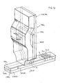
- pole pieces which constitute the magnetic circuit CIRCMA are formed of a plurality of thin layers separated from each other by thin insulating layers these different layers not being shown in FIG. 1a and in FIG. 1b for simplicity.
- the part PPA1 is placed on a non-magnetic SUBSAT insulating substrate (only shown in Figure 1b and not shown in Figure 1a to make it clearer).
- the BOBA coil is formed by a succession of thin conductive layers and insulation superimposed and clamped by the two pole pieces PPA1 and PPA2.
- the pole piece PPA1 preferably has a thickness (dimension measured in a direction parallel to the direction of travel Fa) el, much less than the thickness e2 of the piece PPA2.
- the PPA1 and PPA2 pole pieces are very often made of anisotropic magnetic material.
- the axis of easy magnetization of the pole pieces is the AFAT axis parallel to the SMA recording medium (and perpendicular to the direction of travel Fa of the information).
- the axis of difficult magnetization is the axis ADAT normal to the plane of the magnetic recording medium SMA.
- the SMA recording medium which is arranged opposite the air gap of the TMA1 transducer consists of a layer CMA1 of anisotropic magnetic material placed on a SUBSA substrate.
- the axis of easy magnetization of this magnetic and anisotropic material is designated by AFAM1. It is oriented perpendicular to the surface of the layer (see Figures la and lb).
- a current representative of the information to be written is sent into the winding BOBA, formed of a series of positive and negative pulses of variable duration.
- the magnetic field applied to the pole pieces by the passage of this current in the winding has an important component according to the direction of difficult magnetization of these.
- the BOBA winding constitutes a set of means for generating a magnetic field in the direction of difficult magnetization of the pole pieces and in particular of the downstream pole piece.
- This magnetic field causes the generation, through pole pieces PPA1 and PPA 2, of a magnetic flux which closes through the magnetic layer CMA1 and the substrate SUBSA as shown in FIG. 1b by the lines of magnetic flux LCM.
- the magnetic field has a much weaker intensity than compared to the pole piece PPA1, since the magnetic flux which circulates in the assembly constituted by the two pole pieces PPA1 and PPA2, the magnetic layer CMA1 and the substrate SUBSA, is assumed to be conservative and that the thickness e2 is greater than the thickness el.
- downstream pole piece PPA1 writes the information onto the magnetic recording medium SMA without the writing thereof being disturbed by the upstream pole piece PPA2.
- This downstream pole piece is thus called a writing pole piece
- FIG. 2 represents a TMA2 variant of the TMA1 magnetic transducer, more particularly intended for writing very high density information, both radial and linear, on an SMA recording medium such as a magnetic disk.
- the thin pole piece PPA4 has a tapered shape and has a narrowing at the air gap which has a section whose dimensions are of the order of a micron, which allows it to write information with radial densities and linear sought.
- the transducer of FIG. 2 is inspired by the characteristics used in the aforementioned patent No. 2,297,475.
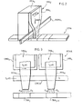
- multi-transducer heads comprising a plurality of transducers of the type from that shown in FIG. 2.
- Such a head according to the prior art is shown in partial view in FIG. 3.
- This head is designated by MTHA.
- MTHA multiple transducers
- FIG. 3 only two transducers TMA3 and TMA4 have been shown, but it is obvious that this MTHA head can contain more transducers.
- the two transducers TMA3 and TMA4 are represented with their thin poles or pole pieces PPA5 and PPA6 writing, the thick poles are not shown to simplify the figure.
- the MTHA multi-transducer head can preferably be produced in the manner described in the aforementioned IEEE TRANSMAG document. It then comprises a first coil formed by the thin conductor CMCA which is common to the two transducers TMA3 and TMA4.
- the transducer TMA3 comprises a second thin conductor in the form of a loop CMB3, while the transducer TMA4 comprises a thin conductor in form of CMB4 loop identical in shape to CMB3.
- these two conductors, between the thick poles and the thin poles are parallel to the common thin conductor CMCA, as can be seen in this same figure 3.
- the operation of the MTHA multi-transducer head is as follows.
- CMCA common conductor
- a current I2 of the same direction as Il is sent into the thin loop-shaped conductor CMB3, which creates in the vicinity of the air gap G3 from the transducer a field H3 sufficient to write information on the track TRAj.
- the CMCA conductor and the CMB 3 conductor form "means for generating a magnetic field in the direction of difficult magnetization of the downstream pole piece PPA S ".
- these means consist of the CMCA conductor and the CMB 4 conductor.
- these can also be defined, as well for the TMA 1 , TMA 2 , TMA 3 , TMA 4 transducers, as writing control means acting on the part. writing pole (downstream pole piece) so that it produces in the immediate vicinity of the support, a magnetic field of sufficient intensity to write the information on the latter.
- TMI transducer according to the invention
- FIGS. 4a and 4b The structure and operation of the transducer according to the invention TMI shown in FIGS. 4a and 4b are such that they allow the constitution of multi-transducer heads overcoming the drawbacks stated above.
- this transducer has an extremely simple and efficient operation.
- the main thin conductor CMPI is perpendicular to the axis of difficult magnetization ADATI of the pole pieces PPI1 and PPI2, while the conductor CMEI is perpendicular to their axis of easy magnetization AFATI. Consequently, the magnetic field created by the passage of a current I1 in the conductor CMPI will be parallel to the axis of difficult magnetization ADATI, while the magnetic field created by the passage of a current I2 in the conductor CMEI creates a magnetic field parallel to the axis of easy magnetization AFATI.
- the TMI transducer is shown arranged above a track TRIj of a magnetic recording medium SMI with an easy magnetization axis AFAMI identical to the SMA support and which for example is a magnetic disc. It scrolls in the direction of the arrow Fi.
- FIG. 4c illustrates the operation of the transducer according to the invention.
- the magnetization (defined as the density of magnetic moments per unit of volume spontaneously orientates in the direction of easy AFATI magnetization (magnetization vector MR in FIG. 4c) (measuring the magnetic moment at each point of the downstream pole piece) .
- the magnetization (vector M f in FIG. 4c) is oriented in a direction forming a angle ⁇ with the AFATI easy axis.
- the TMI transducer has three operating states illustrated in FIGS. 5a to 5c.
- the TMI transducer has been symbolized by the thin pole PPI2, the conductor CMEI and the conductor CMPI.
- the magnetization vector M2 corresponds to a magnetic field H2 in the vicinity of the thin pole PPI2 of the transducer CMI.
- FIGS. 5a, 5b and 5c correspond respectively to three stages in the process of writing information on the magnetic recording medium SMI, these three stages being designated respectively by PH1, PH2, PH3.
- the intensity H3 of the magnetic field created by the TMI transducer in the immediate vicinity of the pole piece PPI2 is sufficient to cause a change of direction of magnetization in the magnetic domain here D6, which is located opposite the thin pole PPI2 at the moment when the current I2 becomes zero, that is to say at l 'instant t3 (see figure 9).
- D6 the period during which the current I2 is zero is extremely small, designated by ht in Figure 9. If 1 2 is zero, we also say that the second means (CMEI conductor) are at rest.
- FIGS. 6a, 6b and 6c correspond magnetic states of the recording medium SMI defined in FIG. 8 where the asteroid of the recording medium SMI has been shown.
- This astroid gives the variation curve of hy / hk as a function of hx / hk.
- hy is the value of the magnetic field in the recording medium along the direction of the easy axis AFAMI
- hx is the value of the magnetic field in the recording medium along the difficult axis perpendicular to the easy axis AFAMI and parallel to the support surface
- hk being the anisotropy field of the anisotropic magnetic medium constituting the SMI recording medium.
- step PH1 corresponds the operating point Pl.
- step PH2 corresponds the operating point P2, the value of the magnetic field applied along the easy axis, due to the presence of the field H2 in the vicinity of the pole PPI2, not being sufficient to switch the magnetizations in the SMI support.
- step PH3 corresponds the operating point P3, where the value of the magnetic field applied inside the support hy3 as a function of the magnetic field H3 produced by the TMI transducer in the immediate vicinity of the pole PPI2 is sufficient to cause the magnetization in the D6 domain, for example.
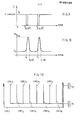
- the current 12 has the shape indicated in this figure, that is to say that it is constant and equal to 10, for example positive between times 0 and t3, zero between the instants t3 and t3 + ⁇ t, at again constant and positive between instants t3 + jt and t4, again zero between instants t4 and t4 + Dt (where the magnetization is switched to another domain (not shown in FIG. 6c) and so on.
- FIG. 9 corresponds to FIG. 10 which represents the variation of the field Hy produced by the PPI2 pole of the TMI transducer in the immediate vicinity thereof.
- this field varies between a value H2 between the instants O and t3 and H3 between the instants t3 and t3 + ⁇ t.
- the field Hy is again equal to H2 between the instants t3 + ⁇ t and t4, again equal H3 between the instants t4 and t4 + ⁇ t.
- FIGS 11 and 12 show a multi-transducer head according to the invention MTHI consisting of a plurality of transducers (namely 8 in the embodiment shown in these figures) namely the transducers TMI1 to TMI8 whose the structure and operating principles are strictly analogous to those of the TMI transducer shown 4a and 4b.
- All of these transducers have a common PECI thick pole.
- the thin poles of the transducers TMI1 to TMI8 are respectively designated by PMI1 to PMI8.
- the head MTHI comprises a common conductor CMCI to all of the transducers TMI1 to TMI8, this common conductor playing the role of the conductor CMPI of the TMI transducer according to the invention shown in FIGS. 4a and 4b.
- a second insulating layer ISI2 is arranged between this common conductor CMCI and the thin poles PMI1 to PMI8, a second insulating layer ISI2 is arranged.
- Each of the transducers TMI1 to TMI8 includes a thin write conductor. These conductors are designated respectively by CMEI1 to CMEI8. These conductors are arranged on their respective thin poles PMI1 to PMI8 in such a way that the latter are located between them and the common conductor CMCI.
- the set of even poles is located above the set of odd poles (compare figures llc and llb by looking at the respective positions of PMI 2 and PMI 1 ) except for the ends of the poles which are closest from the SMI support, at the air gap. These ends of all the poles, even or odd, neighboring the plane of the air gap are coplanar and equidistant from each other, the pitch of the poles being equal to that of the tracks of the support.
- the insulating layer ISI1 comprises recesses EVI1 to EVI8 intended to receive the ends of the thin poles PMI1 to PMI8.
- the simplified electrical control diagram for the various transducers TMI1 to TMI8 of the MTHI platform is extremely simple: the common conductor CMCI is connected to a ground Ml, while all of the eight write control conductors CMEI1 to CMEI8 are connected to the same mass M2.
- this circuit is as follows: if we want to write information given on the SMI support which scrolls in the direction of the arrow Fi in front of the head TMHI (see FIG. Lla) by means of one or more transducers of this head, for example, the CMEI2 and CMEI5 transducers, the current in the CMEI2 and CMEI5 conductors is canceled, as shown in Figure 9.I1 remains understood that in the other conductors, namely CMEI1, CMEI3, CMEI4 to CMEI8, the current remains constant and equal for example to the positive value 10 (see also figure 9).
- the multi-transducer head according to the invention makes it possible to simultaneously write eight pieces of information on eight tracks neighboring the SMI recording medium, without there being any interference between the different transducers.
- the problem of crosstalk between the different transducers is eliminated thanks to the invention.
Landscapes
- Engineering & Computer Science (AREA)
- Manufacturing & Machinery (AREA)
- Recording Or Reproducing By Magnetic Means (AREA)
- Magnetic Heads (AREA)
Applications Claiming Priority (2)
| Application Number | Priority Date | Filing Date | Title |
|---|---|---|---|
| FR8311728 | 1983-07-13 | ||
| FR8311728A FR2549271B1 (fr) | 1983-07-13 | 1983-07-13 | Transducteur magnetique hautement integre d'ecriture d'informations sur un support magnetique |
Publications (2)
| Publication Number | Publication Date |
|---|---|
| EP0132186A1 true EP0132186A1 (de) | 1985-01-23 |
| EP0132186B1 EP0132186B1 (de) | 1988-05-18 |
Family
ID=9290828
Family Applications (1)
| Application Number | Title | Priority Date | Filing Date |
|---|---|---|---|
| EP84401400A Expired EP0132186B1 (de) | 1983-07-13 | 1984-07-03 | Höchstintegrierter Magnetwandler zum Schreiben von Informationen auf einem magnetischen Träger |
Country Status (4)
| Country | Link |
|---|---|
| US (1) | US4622615A (de) |
| EP (1) | EP0132186B1 (de) |
| DE (1) | DE3471386D1 (de) |
| FR (1) | FR2549271B1 (de) |
Cited By (1)
| Publication number | Priority date | Publication date | Assignee | Title |
|---|---|---|---|---|
| US4677513A (en) * | 1983-12-29 | 1987-06-30 | Fuji Photo Film Co., Ltd. | Magneto-optic thin film head and method of use |
Families Citing this family (4)
| Publication number | Priority date | Publication date | Assignee | Title |
|---|---|---|---|---|
| KR100532377B1 (ko) * | 1998-01-15 | 2006-02-08 | 삼성전자주식회사 | 비편향 자기 저항 헤드 |
| US6195230B1 (en) * | 1998-04-27 | 2001-02-27 | Intel Corporation | Disk head assembly with multiple read and/or write transducers for improved performance |
| US6282056B1 (en) | 1999-04-08 | 2001-08-28 | Read-Rite Corporation | Tapered stitch pole writer for high density magnetic recording |
| JP2002216313A (ja) * | 2001-01-15 | 2002-08-02 | Sony Corp | マルチ磁気記録ヘッド並びにこれを用いた磁気記録方法及び磁気記録装置 |
Citations (10)
| Publication number | Priority date | Publication date | Assignee | Title |
|---|---|---|---|---|
| DE1159017B (de) * | 1960-10-25 | 1963-12-12 | Gerhard M Fasching Dipl Ing | Anordnung mit mindestens einem magnetischen Kreis zur Herstellung wahlweiser Verbindungen fuer die UEbertragung von Nachrichten |
| US3271751A (en) * | 1961-12-21 | 1966-09-06 | Ibm | Magnetic thin film transducer |
| US3495230A (en) * | 1966-04-04 | 1970-02-10 | Sperry Rand Corp | Plated wire recording head with selective electronic switching to individual tracks |
| FR1604401A (de) * | 1967-11-08 | 1971-11-08 | ||
| US3633188A (en) * | 1969-07-22 | 1972-01-04 | Burroughs Corp | Electromagnetic transducer employing a thin magnetic film having an oriented easy direction of magnetization |
| US3810191A (en) * | 1972-10-26 | 1974-05-07 | Honeywell Inc | Multi-stylus through field recording head |
| US4222084A (en) * | 1977-06-14 | 1980-09-09 | Tdk Electronics Co., Ltd. | Magnetic head |
| WO1982003938A1 (en) * | 1981-05-06 | 1982-11-11 | Corp Censtor | Magnetic head and multitrack transducer for perpendicular recording and method for fabricating |
| DE3213928A1 (de) * | 1981-04-15 | 1982-11-18 | Canon Denshi K.K., Chichibu, Saitama | Senkrecht - magnetkopf |
| NL8302585A (nl) * | 1982-07-19 | 1984-02-16 | Nippon Telegraph & Telephone | Magneetkop. |
Family Cites Families (10)
| Publication number | Priority date | Publication date | Assignee | Title |
|---|---|---|---|---|
| FR2297475A1 (fr) * | 1975-01-10 | 1976-08-06 | Cii | Perfectionnements exportes aux structures de tetes magnetiques du type dit " integre " |
| US4138702A (en) * | 1975-01-23 | 1979-02-06 | Compagnie Honeywell Bull | Head arrangement for perpendicular recording information on a magnetic record carrier |
| FR2315139A1 (fr) * | 1975-06-19 | 1977-01-14 | Cii | Nouvelle structure de tete magnetique integree |
| FR2384315A1 (fr) * | 1977-03-18 | 1978-10-13 | Cii Honeywell Bull | Plate-forme comportant au moins un transducteur integre et procede de fabrication de ladite plate-forme |
| FR2428886A1 (fr) * | 1978-06-13 | 1980-01-11 | Cii Honeywell Bull | Support d'information magnetique a enregistrement perpendiculaire |
| JPS55146632A (en) * | 1979-04-27 | 1980-11-15 | Fuji Photo Film Co Ltd | Magnetic recording medium and magnetic recording and reproducing method |
| JPS5616932A (en) * | 1979-07-18 | 1981-02-18 | Olympus Optical Co Ltd | Recording and reproducing head for vertical magnetic recording and manufacture of this recording and reproducing head and recording and reproducing unit using this recording and reproducing head |
| FR2468183A1 (fr) * | 1979-10-25 | 1981-04-30 | Cii Honeywell Bull | Transducteur magnetique integre |
| US4317148A (en) * | 1980-01-24 | 1982-02-23 | Sperry Corporation | Transducer for perpendicular magnetic recording |
| US4307053A (en) * | 1980-08-18 | 1981-12-22 | Owens-Corning Fiberglas Corporation | Method and apparatus for processing compressible material |
-
1983
- 1983-07-13 FR FR8311728A patent/FR2549271B1/fr not_active Expired
-
1984
- 1984-06-29 US US06/626,032 patent/US4622615A/en not_active Expired - Fee Related
- 1984-07-03 DE DE8484401400T patent/DE3471386D1/de not_active Expired
- 1984-07-03 EP EP84401400A patent/EP0132186B1/de not_active Expired
Patent Citations (10)
| Publication number | Priority date | Publication date | Assignee | Title |
|---|---|---|---|---|
| DE1159017B (de) * | 1960-10-25 | 1963-12-12 | Gerhard M Fasching Dipl Ing | Anordnung mit mindestens einem magnetischen Kreis zur Herstellung wahlweiser Verbindungen fuer die UEbertragung von Nachrichten |
| US3271751A (en) * | 1961-12-21 | 1966-09-06 | Ibm | Magnetic thin film transducer |
| US3495230A (en) * | 1966-04-04 | 1970-02-10 | Sperry Rand Corp | Plated wire recording head with selective electronic switching to individual tracks |
| FR1604401A (de) * | 1967-11-08 | 1971-11-08 | ||
| US3633188A (en) * | 1969-07-22 | 1972-01-04 | Burroughs Corp | Electromagnetic transducer employing a thin magnetic film having an oriented easy direction of magnetization |
| US3810191A (en) * | 1972-10-26 | 1974-05-07 | Honeywell Inc | Multi-stylus through field recording head |
| US4222084A (en) * | 1977-06-14 | 1980-09-09 | Tdk Electronics Co., Ltd. | Magnetic head |
| DE3213928A1 (de) * | 1981-04-15 | 1982-11-18 | Canon Denshi K.K., Chichibu, Saitama | Senkrecht - magnetkopf |
| WO1982003938A1 (en) * | 1981-05-06 | 1982-11-11 | Corp Censtor | Magnetic head and multitrack transducer for perpendicular recording and method for fabricating |
| NL8302585A (nl) * | 1982-07-19 | 1984-02-16 | Nippon Telegraph & Telephone | Magneetkop. |
Non-Patent Citations (2)
| Title |
|---|
| IBM TECHNICAL DISCLOSURE BULLETIN, vol. 21, no. 2, July 1978, pages 667-668, Armonk, N.Y., US; A. BRUNSCH et al.: "Magnetic read/write thin film head with variable, adjustable anisotropy" * |
| IBM TECHNICAL DISCLOSURE BULLETIN, vol. 3, no. 11, April 1961, page 18, Armonk, N.Y., US; J. FLORA et al.: "Multitrack probe type recording transducer" * |
Cited By (1)
| Publication number | Priority date | Publication date | Assignee | Title |
|---|---|---|---|---|
| US4677513A (en) * | 1983-12-29 | 1987-06-30 | Fuji Photo Film Co., Ltd. | Magneto-optic thin film head and method of use |
Also Published As
| Publication number | Publication date |
|---|---|
| FR2549271A1 (fr) | 1985-01-18 |
| US4622615A (en) | 1986-11-11 |
| DE3471386D1 (en) | 1988-06-23 |
| FR2549271B1 (fr) | 1989-05-26 |
| EP0132186B1 (de) | 1988-05-18 |
Similar Documents
| Publication | Publication Date | Title |
|---|---|---|
| EP0107589B1 (de) | Vorrichtung zum Aufzeichnen von Informationen auf einem magnetischen Träger | |
| EP0340085A2 (de) | Magnetkopf-Matrixanordnung, insbesondere aus Dünnfilmen | |
| EP0023868B1 (de) | Optische Vorrichtung zum Spurzugriff eines Informationsträgers und optisches Speichersystem mit einer solchen Vorrichtung | |
| EP0188944A1 (de) | System für senkrechte Aufzeichnung und Verfahren zur Herstellung eines Magnetkopfes | |
| EP0046697B1 (de) | Integrierter Magnetwandler | |
| EP0035943B1 (de) | Magnetkopf mit veränderbarer Spurbreite zum magnetischen Aufzeichnen oder Wiedergeben von Daten | |
| EP0061363B1 (de) | Magnetoresistiver Lesewandler für grosse Informationsdichtheit | |
| EP0040994B1 (de) | Magnetwandler, der einen Spalt mit veränderbarer Grössen-Dimension aufweist, zur Wiedergabe oder zum Aufzeichnen von Informationen eines magnetischen Trägers | |
| EP0132186B1 (de) | Höchstintegrierter Magnetwandler zum Schreiben von Informationen auf einem magnetischen Träger | |
| EP0188943B1 (de) | Schreib-Magnetwandler zur transversalen Aufzeichnung | |
| FR2944910A1 (fr) | Dispositif de memorisation magnetique a vortex | |
| EP0041409A1 (de) | Magnetwandler zur Wiedergabe oder zum Aufzeichnen von Informationen eines magnetischen Trägers | |
| EP0028177B1 (de) | Integrierter Magnetwandler | |
| FR2648941A1 (fr) | Tete de lecture magnetique a effet hall | |
| EP0409673B1 (de) | Integrierter Magnetaufzeichnungskopf | |
| FR2747226A1 (fr) | Procedes de realisation d'une tete magnetique double a entrefers d'azimuts opposes | |
| EP0611202A1 (de) | Magnetooptischer Wiedergabekopf und Wiedergabegerät für die Wiedergabe von magnetischen Daten auf mehreren Spuren | |
| EP0038754B1 (de) | Magnetischer Blasenspeicher | |
| FR2617629A1 (fr) | Memoire a ligne de bloch et procede pour transferer une ligne de bloch | |
| FR2802011A1 (fr) | Tete de lecture planaire a element magneto-resistif | |
| EP0203849B1 (de) | Magnetischer Blasengenerator für einen Blasenspeicher in hybrider Technologie | |
| FR2493015A1 (fr) | Transducteur magnetoresistant | |
| WO1988004093A1 (fr) | Tete magnetique pour pistes magnetiques a fort champ coercitif et procede de fabrication | |
| BE837647A (fr) | Dispositif de propagation de domaines magnetiques | |
| FR3057418A1 (fr) | Procede de filtrage frequentiel |
Legal Events
| Date | Code | Title | Description |
|---|---|---|---|
| PUAI | Public reference made under article 153(3) epc to a published international application that has entered the european phase |
Free format text: ORIGINAL CODE: 0009012 |
|
| AK | Designated contracting states |
Designated state(s): DE FR GB IT NL |
|
| 17P | Request for examination filed |
Effective date: 19841212 |
|
| 17Q | First examination report despatched |
Effective date: 19861008 |
|
| RAP1 | Party data changed (applicant data changed or rights of an application transferred) |
Owner name: BULL S.A. |
|
| ITF | It: translation for a ep patent filed |
Owner name: FUMERO BREVETTI S.N.C. |
|
| GRAA | (expected) grant |
Free format text: ORIGINAL CODE: 0009210 |
|
| AK | Designated contracting states |
Kind code of ref document: B1 Designated state(s): DE FR GB IT NL |
|
| REF | Corresponds to: |
Ref document number: 3471386 Country of ref document: DE Date of ref document: 19880623 |
|
| GBT | Gb: translation of ep patent filed (gb section 77(6)(a)/1977) | ||
| PLBE | No opposition filed within time limit |
Free format text: ORIGINAL CODE: 0009261 |
|
| STAA | Information on the status of an ep patent application or granted ep patent |
Free format text: STATUS: NO OPPOSITION FILED WITHIN TIME LIMIT |
|
| PGFP | Annual fee paid to national office [announced via postgrant information from national office to epo] |
Ref country code: FR Payment date: 19890512 Year of fee payment: 6 |
|
| 26N | No opposition filed | ||
| PGFP | Annual fee paid to national office [announced via postgrant information from national office to epo] |
Ref country code: GB Payment date: 19890531 Year of fee payment: 6 |
|
| ITTA | It: last paid annual fee | ||
| PGFP | Annual fee paid to national office [announced via postgrant information from national office to epo] |
Ref country code: NL Payment date: 19890731 Year of fee payment: 6 |
|
| PGFP | Annual fee paid to national office [announced via postgrant information from national office to epo] |
Ref country code: DE Payment date: 19890803 Year of fee payment: 6 |
|
| PG25 | Lapsed in a contracting state [announced via postgrant information from national office to epo] |
Ref country code: GB Effective date: 19900703 |
|
| PG25 | Lapsed in a contracting state [announced via postgrant information from national office to epo] |
Ref country code: NL Effective date: 19910201 |
|
| GBPC | Gb: european patent ceased through non-payment of renewal fee | ||
| NLV4 | Nl: lapsed or anulled due to non-payment of the annual fee | ||
| PG25 | Lapsed in a contracting state [announced via postgrant information from national office to epo] |
Ref country code: FR Effective date: 19910329 |
|
| PG25 | Lapsed in a contracting state [announced via postgrant information from national office to epo] |
Ref country code: DE Effective date: 19910403 |
|
| REG | Reference to a national code |
Ref country code: FR Ref legal event code: ST |