EP0132053A2 - Ventilaufbau - Google Patents
Ventilaufbau Download PDFInfo
- Publication number
- EP0132053A2 EP0132053A2 EP84304075A EP84304075A EP0132053A2 EP 0132053 A2 EP0132053 A2 EP 0132053A2 EP 84304075 A EP84304075 A EP 84304075A EP 84304075 A EP84304075 A EP 84304075A EP 0132053 A2 EP0132053 A2 EP 0132053A2
- Authority
- EP
- European Patent Office
- Prior art keywords
- valve
- chamber
- disc
- side wall
- radiator
- Prior art date
- Legal status (The legal status is an assumption and is not a legal conclusion. Google has not performed a legal analysis and makes no representation as to the accuracy of the status listed.)
- Withdrawn
Links
- 239000012530 fluid Substances 0.000 claims abstract description 16
- 238000007789 sealing Methods 0.000 claims abstract description 8
- 230000000717 retained effect Effects 0.000 claims abstract description 7
- 238000004891 communication Methods 0.000 claims description 2
- 230000002093 peripheral effect Effects 0.000 claims 2
- 238000010438 heat treatment Methods 0.000 description 5
- 230000004044 response Effects 0.000 description 4
- 230000005855 radiation Effects 0.000 description 2
- 230000004913 activation Effects 0.000 description 1
- 230000008878 coupling Effects 0.000 description 1
- 238000010168 coupling process Methods 0.000 description 1
- 238000005859 coupling reaction Methods 0.000 description 1
- 238000000034 method Methods 0.000 description 1
- 229920001296 polysiloxane Polymers 0.000 description 1
- 230000008569 process Effects 0.000 description 1
- 230000009467 reduction Effects 0.000 description 1
- 230000008439 repair process Effects 0.000 description 1
- 239000010865 sewage Substances 0.000 description 1
- 229910000679 solder Inorganic materials 0.000 description 1
- XLYOFNOQVPJJNP-UHFFFAOYSA-N water Substances O XLYOFNOQVPJJNP-UHFFFAOYSA-N 0.000 description 1
Images

Classifications
-
- F—MECHANICAL ENGINEERING; LIGHTING; HEATING; WEAPONS; BLASTING
- F24—HEATING; RANGES; VENTILATING
- F24D—DOMESTIC- OR SPACE-HEATING SYSTEMS, e.g. CENTRAL HEATING SYSTEMS; DOMESTIC HOT-WATER SUPPLY SYSTEMS; ELEMENTS OR COMPONENTS THEREFOR
- F24D19/00—Details
- F24D19/0002—Means for connecting central heating radiators to circulation pipes
- F24D19/0009—In a two pipe system
- F24D19/0012—Comprising regulation means
-
- G—PHYSICS
- G05—CONTROLLING; REGULATING
- G05D—SYSTEMS FOR CONTROLLING OR REGULATING NON-ELECTRIC VARIABLES
- G05D23/00—Control of temperature
- G05D23/01—Control of temperature without auxiliary power
- G05D23/02—Control of temperature without auxiliary power with sensing element expanding and contracting in response to changes of temperature
- G05D23/08—Control of temperature without auxiliary power with sensing element expanding and contracting in response to changes of temperature with bimetallic element
Definitions
- This invention relates to heating systems more especially two pipe steam heating systems.
- thermostatically steam trapped radiator systems exhibit a number of perplexing disadvantages.
- thermostatic steam traps are susceptible to failure and such failures are difficult to diagnose.
- faulty traps are diagnosed with relatively expensive infra-red equipment that must make difficult distinctions between operating temperatures of about 88 0 C and 99°C.
- Even after a given trap has been accurately diagnosed as faulty the repair thereof is a relatively expensive process.
- Another disadvantage is relatively poor energy efficiency resulting from the steam traps discharge of condensate at either steam temperature or slightly below. That factor also is responsible for the annoying hammering, clapping and vibration sounds commonly associated with such systems.
- Still other problems associated with thermostatic steam trap radiator systems stem from the restrictions to high temperature condensate in many municipal sewage systems.
- An object of the invention is to provide an improved steam heating system that alleviates many of the problems encountered by users thermostatic steam traps.
- the invention is a thermostatic valve including a housing that defines a housing inlet and a housing outlet and a valve body having an end wall and a side wall that define a valve chamber within the housing.
- the end wall defines an annular valve seat and a valve inlet opening encircled thereby while the side wall defines a plurality of valve outlet openings communicating with the valve chamber.
- Retained within the valve chamber is a resilient, annular seal encircling the valve inlet opening and a bi-metalic disc substantially parallel to the valve seat and normally spaced therefrom by a distance greater than the thickness of the annular seal.
- the bi-metalic disc deflects concavely into the valve chamber and into fluid sealing engagement with one end of the annular seal forcing an opposite end thereof into fluid sealing engagement with the valve seat.
- the invention includes a steam radiator having a radiator inlet and a radiator outlet communicating with the housing inlet, and a thermostatically controlled steam trap connected for communication with the housing outlet.
- the thermostatic valve supersedes the thermostatic steam trap thereby eliminating problems associated with its use.
- the valve's side wall is a cylindrical wall normal to its end wall and defining circumferentially spaced apart, radially directed outlet passages md
- the seal is a resilient 0-ring having a thickness defined by its opposite ends and an outer diameter that is less than the inner diameter of the cylindrical side wall.
- the housing comprises a union and the valve body comprises an annular skirt extending outwardly from the cylindrical side wall and retained by the union.
- This featured valve is easily installed into the pipe union that is typically provided between a conventional thermostatic steam trap and the outlet of a steam radiator.
- the bi-metalic disc is adapted to deflect inwardly and close the valve in response to an ambient temperature of between 49°C and 60°C. Operation of the valve in this relatively low temperature range ensures that operation of the thermostatically controlled steam trap will be superseded and results in relatively low temperature condensate discharge that greatly improves the thermal efficiency of the system.
- thermostatically controlled trap 18 would close the outlet 16 to retain steam being supplied by the boiler and resulting in the radiation of heat from the radiator 12. Shortly after a central thermostat has de-activated the boiler, the trap 18 would open the outlet 16 allowing the residual fluid content of the radiator 12 to empty into a return main that carries condensed water back to the boiler.
- that operation of the trap 18 is superseded by a thermostatically controlled valve shown in Figs 2 and 3.
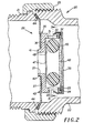
- a union housing 20 between the radiator 12 and the trap 18 includes an outlet pipe 21 from the radiator 12, an externally threaded inlet pipe 22 to the trap 18 and an internally threaded annular coupling 23. Defined by the pipes 21 and 22, respectively are an inlet and an outlet of the union housing 20. As shown, the housing 20 retains a temperature controlled valve 25 that controls fluid flow between the inlet 21 and the outlet 22.
- the valve 25 includes a valve body 26 formed by an end wall 27 and a cylindrical side wall 28 projecting normally therefrom. Centrally defined in the end wall 27 is a valve inlet opening 29 while circumferentially spaced apart, radially directed valve outlet passages 31 are defined by the cylindrical side wall 28.
- the outer end of the cylindrical side wall 28 defines an annular shoulder portion 30 and axially projecting rim portion 32.
- An annular retainer ring 33 is staked under the shoulder portion 30 and forms therewith and the rim portion 32 an annular recess 34.
- Loosely retained in the annular recess 34 is the periphery of a bi-metalic disc 35.
- the disc 35 and the valve body 26 form a valve chamber 36.
- Extending outwardly from the central portion of the end wall 27 is a hollow neck portion 41 that accommodates a central opening 42 in a disc skirt 43.
- the disc is secured, for example by solder, to the valve body 26.
- An outer portion 44 of the skirt 43 extends beyond the sidewall 28 and is engaged in a fluid tight manner between the pipes 21 and 22.
- a resilient 0-ring 45 Disposed within the valve chamber 36 is a resilient 0-ring 45 formed, for example, of silicone.
- the 0-ring 45 encircles the valve inlet opening 29 and has one end 47 directly adjacent an annular valve seat 48 formed by an inner surface portion of the end wall 27.
- An opposite end 49 of the 0-ring 45 is disposed directly adjacent to the bi-metalic disc 35.
- the thickness of the 0-ring 45 defined by its ends 47 and 49 is less than the normal spacing between the valve seat 48 and the bi-metalic disc 35.
- the outer diameter of the 0-ring 45 is slightly less than the inner diameter of the cylindrical side-wall 28.
- valve inlet 29 and the valve outlets 31 flow passages between the 0-ring 45 and, respectively, the valve seat 48, the bi-metalic disc 35 and the inner surface of the cylindrical side wall 28. It should be understood that these clearances are slightly exaggerated in Figs 2 and 3 for purposes of clarity.
- the bi-metalic disc 35 In response to a predetermined ambient temperature, however, the bi-metalic disc 35 deflects concavely into the valve chamber 36 as shown by dotted lines in Fig 2. The deflected disc 35 sealingly engages the end 49 of the 0-ring 46 and forces the opposite end 47 thereof into sealing engagement with the valve seat 48. Thus, fluid flow is prevented between the valve inlet 29 and the valve outlets 31. In response to a subsequent reduction in ambient temperature, the bi-metalic disc 35 returns to its original position and again allows fluid flow between the valve inlet 29 and the valve outlets 31.
- the bi-metalic disc 35 In operation when steam is supplied by a boiler to the radiator 12, the bi-metalic disc 35 quickly reaches a predetermined activation temperature, preferably of about 54°C, and deflects inwardly to close the valve 25. Thus, steam is retained by the radiator 12 resulting in radiation of heat therefrom. Some time after the supply of steam to the radiator 12 has terminated, the ambient temperature of the disc 35 will fall to a given return temperature, preferably of about 38°C. The resultant return of the bi-metalic disc 35 to its undeflected position re-opens the valve 25 allowing a discharge of the residual fluid within the radiator 12. That fluid, primarily condensate, passes through the steam trap 18 to a return main (not shown). Thus, steam never reaches the trap 18 and its function is completely superseded by the valve 25. For that reason, the present invention completely eliminates the heretofore described problems associated with conventional thermostatically controlled steam trap heating systems.
Landscapes
- Engineering & Computer Science (AREA)
- Physics & Mathematics (AREA)
- Thermal Sciences (AREA)
- Chemical & Material Sciences (AREA)
- Combustion & Propulsion (AREA)
- Mechanical Engineering (AREA)
- General Engineering & Computer Science (AREA)
- General Physics & Mathematics (AREA)
- Automation & Control Theory (AREA)
- Temperature-Responsive Valves (AREA)
- Domestic Hot-Water Supply Systems And Details Of Heating Systems (AREA)
- Lift Valve (AREA)
Applications Claiming Priority (2)
| Application Number | Priority Date | Filing Date | Title |
|---|---|---|---|
| US511884 | 1983-07-08 | ||
| US06/511,884 US4527733A (en) | 1983-07-08 | 1983-07-08 | Check valve |
Publications (2)
| Publication Number | Publication Date |
|---|---|
| EP0132053A2 true EP0132053A2 (de) | 1985-01-23 |
| EP0132053A3 EP0132053A3 (de) | 1985-10-30 |
Family
ID=24036853
Family Applications (1)
| Application Number | Title | Priority Date | Filing Date |
|---|---|---|---|
| EP84304075A Withdrawn EP0132053A3 (de) | 1983-07-08 | 1984-06-18 | Ventilaufbau |
Country Status (6)
| Country | Link |
|---|---|
| US (1) | US4527733A (de) |
| EP (1) | EP0132053A3 (de) |
| JP (1) | JPS6086335A (de) |
| CA (1) | CA1217693A (de) |
| DK (1) | DK334284A (de) |
| NO (1) | NO842767L (de) |
Families Citing this family (6)
| Publication number | Priority date | Publication date | Assignee | Title |
|---|---|---|---|---|
| US4646965A (en) * | 1985-08-26 | 1987-03-03 | Bimax Controls, Inc. | Thermostatic steam trap |
| US5479786A (en) * | 1994-03-29 | 1996-01-02 | Texas Instruments Incorporated | Flow regulating valve apparatus for air conditioning systems |
| US6450412B1 (en) * | 2001-04-10 | 2002-09-17 | Pgi International, Ltd. | Temperature actuated flow restrictor |
| CN101358659B (zh) * | 2007-07-30 | 2010-10-06 | 徐佳义 | 蒸具自动节流排气阀门装置 |
| CN113465182A (zh) * | 2021-06-24 | 2021-10-01 | 广东万和新电气股份有限公司 | 一种热水器、热水供应系统及其控制方法 |
| KR102870605B1 (ko) * | 2022-08-26 | 2025-10-21 | 주식회사 경동나비엔 | 재순환 밸브 |
Family Cites Families (12)
| Publication number | Priority date | Publication date | Assignee | Title |
|---|---|---|---|---|
| US2203759A (en) * | 1938-08-27 | 1940-06-11 | Elmer G Ware | Pump valve with gas chamber in cage |
| US2346590A (en) * | 1942-02-14 | 1944-04-11 | Vapor Car Heating Co Inc | Inner-tube radiation with modulating trap |
| US3411712A (en) * | 1966-06-23 | 1968-11-19 | Carrier Corp | Bimetallic disc valve flow diverter |
| IT1024413B (it) * | 1973-12-26 | 1978-06-20 | Texas Instruments Inc | Perfezionamento nei complessi a valvola per fluidi comprendenti un elemento termostatico bimetallico |
| US3930613A (en) * | 1974-10-18 | 1976-01-06 | Therm-O-Disc Incorporated | Check valve having temperature response |
| DE2453757C3 (de) * | 1974-11-13 | 1980-07-24 | Pierburg Gmbh & Co Kg, 4040 Neuss | Thermoventil für Brennkraftmaschinen |
| JPS5632685Y2 (de) * | 1975-05-16 | 1981-08-03 | ||
| GB1537315A (en) * | 1975-06-02 | 1978-12-29 | Texas Instruments Inc | Thermally responsive valve assemblies |
| US4133478A (en) * | 1977-02-07 | 1979-01-09 | Therm-O-Disc Incorporated | Temperature responsive valve |
| US4142677A (en) * | 1977-06-27 | 1979-03-06 | Tom Mcguane Industries, Inc. | Fuel vapor vent valve |
| US4156518A (en) * | 1977-08-29 | 1979-05-29 | Tom Mcguane Industries, Inc. | Electric vacuum valve |
| US4262844A (en) * | 1980-01-22 | 1981-04-21 | Mark Controls Corporation | Control valve |
-
1983
- 1983-07-08 US US06/511,884 patent/US4527733A/en not_active Expired - Fee Related
-
1984
- 1984-06-18 EP EP84304075A patent/EP0132053A3/de not_active Withdrawn
- 1984-06-26 CA CA000457490A patent/CA1217693A/en not_active Expired
- 1984-07-05 JP JP59138110A patent/JPS6086335A/ja active Pending
- 1984-07-06 DK DK334284A patent/DK334284A/da not_active Application Discontinuation
- 1984-07-06 NO NO842767A patent/NO842767L/no unknown
Also Published As
| Publication number | Publication date |
|---|---|
| DK334284A (da) | 1985-01-09 |
| DK334284D0 (da) | 1984-07-06 |
| US4527733A (en) | 1985-07-09 |
| JPS6086335A (ja) | 1985-05-15 |
| NO842767L (no) | 1985-01-09 |
| CA1217693A (en) | 1987-02-10 |
| EP0132053A3 (de) | 1985-10-30 |
Similar Documents
| Publication | Publication Date | Title |
|---|---|---|
| US4527733A (en) | Check valve | |
| US4646965A (en) | Thermostatic steam trap | |
| US970095A (en) | Vacuum-wall hot-water tank. | |
| GB2029000A (en) | Steam-trap or other valve with temperature-responsive control means | |
| US4828169A (en) | Adjustable air valve | |
| US2012067A (en) | Automatically controlled heating system | |
| JP2709536B2 (ja) | 熱応動式スチ―ムトラップ | |
| US1688092A (en) | Combination relief valve | |
| ATE8429T1 (de) | Sicherheitsventil. | |
| US2188441A (en) | Air valve | |
| US6371437B1 (en) | Thermally operated valve for automatically modulating the flow of fluids and methods and tool for making the same | |
| KR100378110B1 (ko) | 압력하의 유체유동을 조정하기 위한 밸브 유니트 | |
| US92622A (en) | Improvement in steam water-heaters | |
| US1166531A (en) | Water-heater. | |
| US2788177A (en) | Steam heating system | |
| US2461136A (en) | Control valve | |
| US318401A (en) | Steam-heating apparatus | |
| US1847053A (en) | Venting appliance for heating systems | |
| US1875246A (en) | Heating system | |
| US208520A (en) | Improvement in steam-traps | |
| US854450A (en) | Liquid-heating system. | |
| US4191327A (en) | Automatic thermostatic control for a steam trap radiator | |
| US2432838A (en) | Thermostatic steam trap | |
| JPS6241124Y2 (de) | ||
| US962550A (en) | Steam-heating system. |
Legal Events
| Date | Code | Title | Description |
|---|---|---|---|
| PUAI | Public reference made under article 153(3) epc to a published international application that has entered the european phase |
Free format text: ORIGINAL CODE: 0009012 |
|
| AK | Designated contracting states |
Designated state(s): DE GB SE |
|
| PUAL | Search report despatched |
Free format text: ORIGINAL CODE: 0009013 |
|
| AK | Designated contracting states |
Designated state(s): DE GB SE |
|
| 17P | Request for examination filed |
Effective date: 19860417 |
|
| 17Q | First examination report despatched |
Effective date: 19860813 |
|
| STAA | Information on the status of an ep patent application or granted ep patent |
Free format text: STATUS: THE APPLICATION IS DEEMED TO BE WITHDRAWN |
|
| 18D | Application deemed to be withdrawn |
Effective date: 19861224 |
|
| RIN1 | Information on inventor provided before grant (corrected) |
Inventor name: ANDERSON, ARTHUR H. |