EP0131850A2 - Conductor for a submarine power cable, and method of manufacturing such a conductor - Google Patents
Conductor for a submarine power cable, and method of manufacturing such a conductor Download PDFInfo
- Publication number
- EP0131850A2 EP0131850A2 EP84107811A EP84107811A EP0131850A2 EP 0131850 A2 EP0131850 A2 EP 0131850A2 EP 84107811 A EP84107811 A EP 84107811A EP 84107811 A EP84107811 A EP 84107811A EP 0131850 A2 EP0131850 A2 EP 0131850A2
- Authority
- EP
- European Patent Office
- Prior art keywords
- conductor
- angle
- manufacturing
- wires
- speed
- Prior art date
- Legal status (The legal status is an assumption and is not a legal conclusion. Google has not performed a legal analysis and makes no representation as to the accuracy of the status listed.)
- Granted
Links
- 239000004020 conductor Substances 0.000 title claims abstract description 25
- 238000004519 manufacturing process Methods 0.000 title claims description 6
- 230000000737 periodic effect Effects 0.000 claims description 6
- 239000002184 metal Substances 0.000 claims description 2
- 238000000034 method Methods 0.000 description 6
- 229910000831 Steel Inorganic materials 0.000 description 2
- 230000005540 biological transmission Effects 0.000 description 2
- 239000010959 steel Substances 0.000 description 2
- 238000004804 winding Methods 0.000 description 2
- 241000287107 Passer Species 0.000 description 1
- 239000004698 Polyethylene Substances 0.000 description 1
- 229920003020 cross-linked polyethylene Polymers 0.000 description 1
- 239000004703 cross-linked polyethylene Substances 0.000 description 1
- 238000009434 installation Methods 0.000 description 1
- 210000000056 organ Anatomy 0.000 description 1
- -1 polyethylene Polymers 0.000 description 1
- 229920000573 polyethylene Polymers 0.000 description 1
- 239000004065 semiconductor Substances 0.000 description 1
Images

Classifications
-
- H—ELECTRICITY
- H01—ELECTRIC ELEMENTS
- H01B—CABLES; CONDUCTORS; INSULATORS; SELECTION OF MATERIALS FOR THEIR CONDUCTIVE, INSULATING OR DIELECTRIC PROPERTIES
- H01B13/00—Apparatus or processes specially adapted for manufacturing conductors or cables
- H01B13/02—Stranding-up
- H01B13/0214—Stranding-up by a twisting pay-off device
-
- H—ELECTRICITY
- H01—ELECTRIC ELEMENTS
- H01B—CABLES; CONDUCTORS; INSULATORS; SELECTION OF MATERIALS FOR THEIR CONDUCTIVE, INSULATING OR DIELECTRIC PROPERTIES
- H01B13/00—Apparatus or processes specially adapted for manufacturing conductors or cables
- H01B13/22—Sheathing; Armouring; Screening; Applying other protective layers
- H01B13/26—Sheathing; Armouring; Screening; Applying other protective layers by winding, braiding or longitudinal lapping
Definitions
- the present invention relates to a conductor for a submarine energy cable, as well as to a method for manufacturing such a conductor.
- a submarine energy cable is essentially made up of one to three conductors wired at constant pitch and insulated, the whole being surrounded by armor made of steel wires laid in a helix.
- the purpose of this armor is to protect the insulating layers and to increase the tensile strength of the cable.
- the object of the invention is to obtain a lower tensile modulus than that obtained by helical wiring with constant pitch to reduce the force F 1 supported by the conductor.
- the subject of the present invention is a conductor for an underwater energy cable, consisting of at least one layer of wired metal wires, characterized in that all the wires are wired in the same direction and at a periodically variable angle.
- each conductor wire can follow this elongation by modifying its geometrical position by approaching the mean helix without elongation of the wire itself.
- the pitch of the ripple generated by the periodically variable angle is less than twice the average pitch of wiring.
- the peak-peak amplitude of the undulation of the wires is less than 0.1 times the pitch of the undulation.
- the present invention also relates to a manufacturing process characterized in that a periodic variation of the angle of commettage.
- the periodic variation of the angle of commetting is obtained by modulating the speed of rotation of the wiring grid through which said wires pass.
- the periodic variation of the angle of commetting is obtained by modulating the speed of the capstan which receives said wires.
- the cage 1 is driven in rotation from the main shaft 5 by means of a transmission comprising a gearbox 6.
- a drawing capstan 7 is also driven from the main shaft through a gearbox 8.
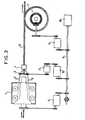
- FIG. 2 shows the stranding machine equipped with a speed variation system w of the distribution grid.
- a grid 9 is mounted which is driven independently of the cage by means of a transmission equipped with a gearbox 10 having ratios identical to those of the gearbox 6 of the cage.
- a speed modulator 11 is added to the kinematic chain.
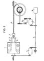
- FIG. 3 shows the stranding machine equipped with a speed variation system v for drawing the capstan 7.
- a speed modulator 12 is added.
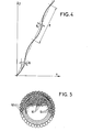
- the pitch of the wire ripple is p and the value of its peak-peak ripple is ⁇ .
- the value of p is preferably less than twice the average wiring pitch.
- the value of is chosen between 3% and 7%, which corresponds to a geometric elongation of the wires from 0.2% to 1%.
- FIG. 5 shows an underwater energy cable comprising a single conductor composed of wires 50 according to the invention.
- This conductor is surrounded by several insulating layers 51 which may be made of paper impregnated with oil, or of polyethylene or crosslinked polyethylene.
- the layer 51 directly in contact with the conductor can be semiconductor to ensure a better distribution of the potential.
- a weave 52 of steel wires surrounds the assembly.
Landscapes
- Engineering & Computer Science (AREA)
- Manufacturing & Machinery (AREA)
- Insulated Conductors (AREA)
- Non-Insulated Conductors (AREA)
- Processes Specially Adapted For Manufacturing Cables (AREA)
- Ropes Or Cables (AREA)
- Manufacturing Of Electric Cables (AREA)
Abstract
Conducteur pour câble sous-marin d'énergie, constitué par au moins une couche de fils métalliques câblés (50), catactérisé par le fait que des tous les fils sont câblés dans un même sens et suivant un angle périodiquement variable.Conductor for submarine energy cable, consisting of at least one layer of cabled metallic wires (50), characterized by the fact that all the wires are wired in the same direction and at a periodically variable angle.
Description
La présente invention concerne un conducteur pour câble sous-marin d'énergie, ainsi qu'un procédé de fabrication d'un tel conducteur.The present invention relates to a conductor for a submarine energy cable, as well as to a method for manufacturing such a conductor.
Un câble sous-marin d'énergie est constitué essentiellement par un à trois conducteurs oâblés à pas constant et isolés, l'ensemble étant entouré par une armure en fils d'acier posés en hélice. Cette armure a pour but de protéger les couches isolantes et d'accroître la résistance du câble à la traction.A submarine energy cable is essentially made up of one to three conductors wired at constant pitch and insulated, the whole being surrounded by armor made of steel wires laid in a helix. The purpose of this armor is to protect the insulating layers and to increase the tensile strength of the cable.
Au cours de la pose le câble est soumis à une force de traction F provoquée par son propre poids. Il en résulte, un allongement du câble généralement inférieur à 1%, une force F dans le conducteur et une force F2 dans l'armure avec F = F + F2* Mais par suite du module de traction élevé d'un conducteur câblé à pas constant on a souvent F supérieure à F2 et l'armure ne joue pas pleinement son rôle de porteur, ce qui est particulièrement important pour les câbles immergés à grande profondeur.During installation, the cable is subjected to a tensile force F caused by its own weight. This results in an elongation of the cable generally less than 1%, a force F in the conductor and a force F2 in the armor with F = F + F 2 * But as a result of the high tensile modulus of a conductor wired to not constant, we often have F greater than F 2 and the armor does not fully play its role of carrier, which is particularly important for cables submerged at great depth.
L'invention a pour but d'obtenir un module de traction plus faible que celui obtenu par un câblage hélicoïdal à pas constant pour diminuer la force F1 supportée par le conducteur.The object of the invention is to obtain a lower tensile modulus than that obtained by helical wiring with constant pitch to reduce the force F 1 supported by the conductor.
La présente invention a pour objet un conducteur pour câble sous-marin d'énergie, constitué par au moins une couche de fils métalliques câblés, caractérisé par le fait que toul les fils sont câblés dans un même sens et suivant un angle périodiquement variable.The subject of the present invention is a conductor for an underwater energy cable, consisting of at least one layer of wired metal wires, characterized in that all the wires are wired in the same direction and at a periodically variable angle.
Il en résulte que tous les fils serpentent de part et d'autre d'une hélice moyenne d'enroulement. Ainsi, lors d'un allongement du conducteur, chaque fil du conducteur pourra suivre cet allongement par modification de sa position géométrique en se rapprochant de l'hélice moyenne sans allongement du fil lui-même.As a result, all of the wires wind on either side of an average winding helix. Thus, during an elongation of the conductor, each conductor wire can follow this elongation by modifying its geometrical position by approaching the mean helix without elongation of the wire itself.
De préférence, le pas de l'ondulation engendrée par l'angle périodiquement variable est inférieur à deux fois le pas moyen de câblage.Preferably, the pitch of the ripple generated by the periodically variable angle is less than twice the average pitch of wiring.
Avantageusement l'amplitude crête-crête de l'ondulation des fils est inférieure à 0,1 fois le pas de l'ondulation.Advantageously, the peak-peak amplitude of the undulation of the wires is less than 0.1 times the pitch of the undulation.
La présente invention a également pour objet un procédé de fabrication caractérisé en ce que l'on effectue une variation périodique de l'angle de commettage.The present invention also relates to a manufacturing process characterized in that a periodic variation of the angle of commettage.
Selon un premier mode de mise en oeuvre de ce procédé, on obtient la variation périodique de l'angle de commettage par la modulation de la vitesse de rotation de la grille de câblage à travers laquelle passent lesdits fils.According to a first embodiment of this method, the periodic variation of the angle of commetting is obtained by modulating the speed of rotation of the wiring grid through which said wires pass.
Selon un second mode de mise en oeuvre de ce procédé, on obtient la variation périodique de l'angle de commettage par la modulation de la vitesse du cabestan qui reçoit lesdits fils.According to a second mode of implementation of this method, the periodic variation of the angle of commetting is obtained by modulating the speed of the capstan which receives said wires.
D'autres caractéristiques et avantages de la présente invention apparaîtront au cours de la description suivante de modes de réalisation donnés à titre illustratif mais nullement limitatif. Dans le dessin annexé :
- - la figure 1 montre très schématiquement les éléments essentiels d'une câbleuse,
- - la figure 2 montre une première variante de la câbleuse de la figure 1 permettant la mise en oeuvre du procédé selon l'invention,
- - la figure 3 montre une seconde variante de la câbleuse de la figure 1 permettant la mise en oeuvre du procédé selon l'invention,
- - la figure 4 est la développée d'un fil appartenant à un conducteur câblé selon le procédé de l'invention,
- - la figure 5 est une coupe schématique d'un câble sous-marin d'énergie comportant un conducteur selon l'invention.
- FIG. 1 very schematically shows the essential elements of a stranding machine,
- FIG. 2 shows a first variant of the stranding machine of FIG. 1 enabling the method according to the invention to be implemented,
- FIG. 3 shows a second variant of the stranding machine of FIG. 1 enabling the method according to the invention to be implemented,
- FIG. 4 is the development of a wire belonging to a conductor wired according to the method of the invention,
- - Figure 5 is a schematic section of an undersea energy cable comprising a conductor according to the invention.
La figure 1 montre la disposition schématique des organes principaux d'une câbleuse :
- Celle-ci se compose d'une ou de plusieurs cages 1 portant chacune plusieurs bobines de fils 2. Ces fils traversent une grille de répartition 3 solidaire de la cage 1, avant de converger sur la filière de câblage 4 d'où sort un
conducteur 21. Unmoteur 20 entraîne un arbre principal 5 en rotation.
- This consists of one or more cages 1 each carrying several coils of wires 2. These wires pass through a distribution grid 3 secured to the cage 1, before converging on the wiring die 4 from which a conductor emerges. 21. A
motor 20 drives a main shaft 5 in rotation.
La cage 1 est entraînée en rotation à partir de l'arbre principal 5 au moyen d'une transmission comportant une boîte de vitesse 6. Un cabestan de tirage 7 est lui aussi entraîné à partir de l'arbre principal à travers une boîte de vitesse 8.The cage 1 is driven in rotation from the main shaft 5 by means of a transmission comprising a gearbox 6. A drawing capstan 7 is also driven from the main shaft through a gearbox 8.
Si UU est la vitesse de rotation instantanée de la cage et de sa grille de répartition et v la vitesse de tirage instantanée du cabestan, pour un rayon d'enroulement r au niveau du conducteur, l'angle de commettage est :
- a/ par modulation de la vitesse de rotation uV de la grille de répartition
- b/ par modulation de la vitesse de tirage v (qui est en fait une modulation de la vitesse de rotation ω' du cabestan)
- a / by modulating the speed of rotation uV of the distribution grid
- b / by modulation of the drawing speed v (which is in fact a modulation of the speed of rotation ω 'of the capstan)
La figure 2 montre la câbleuse équipée d'un système de variation de vitesse w de la grille de répartition. A la place de la grille 3 de la figure 1, on monte une grille 9 entraînée indépendamment de la cage au moyen d'une transmission équipée d'une boîte de vitesse 10 possédant des rapports identiques à ceux de la boite de vitesse 6 de la cage. On ajoute en plus dans la chaîne cinématique un modulateur de vitesse 11.FIG. 2 shows the stranding machine equipped with a speed variation system w of the distribution grid. In place of the grid 3 in FIG. 1, a grid 9 is mounted which is driven independently of the cage by means of a transmission equipped with a
La figure 3 montre la câbleuse équipée d'un système de variation de vitesse v de tirage du cabestan 7. Dans la chaîne cinématique de commande du cabestan on ajoute un modulateur de vitesse 12.FIG. 3 shows the stranding machine equipped with a speed variation system v for drawing the capstan 7. In the kinematic chain for controlling the capstan a
Divers dispositifs mécaniques ou électriques connus permettent d'obtenir une vitesse de rotation périodiquement variables. A titre d'exemple on en cite quatre du domaine de la mécanique :
- 1 - L'utilisation d'une boîte de vitesse à trains planétaires à deux. vitesses. On peut passer d'une vitesse à l'autre par simple freinage des planétaires. On obtient ainsi ω≃ ω1 ou ω ≃ ω2
- 2 - L'utilisation d'un ou de plusieurs joints de cardan. La vitesse de sortie d'un tel joint varie avec l'angle θ du joint suivant la relation ω = ωo (1 + θ2 sin 2 ωot) pour & petit.
- 3 - L'utilisation d'engrenages à rapport non constant. Ce sont des engrenages non de révolution tels que par exemple les engrenages elliptiques. Leur rapport moyen est en général l'unité.
- 4 - L'utilisation d'un différentiel permettant de superposer à la rotation uniforme de l'arbre moteur, un mouvement oscillant produit par ailleurs.
- 1 - The use of a two-speed planetary gearbox. speeds. You can go from one speed to another by simply braking the planets. We thus obtain ω≃ ω 1 or ω ≃ ω 2
- 2 - The use of one or more universal joints. The exit speed of such a joint varies with the angle θ of the joint according to the relation ω = ω o (1 + θ 2 sin 2 ω o t) for & small.
- 3 - The use of non-constant ratio gears. These are non-revolution gears such as for example elliptical gears. Their average ratio is generally unity.
- 4 - The use of a differential allowing to superimpose on the uniform rotation of the motor shaft, an oscillating movement produced by elsewhere.
Tous les moyens précités permettent d'obtenir un conducteur dont les fils sont câblés avec un angle de oommettage périodiquement variable.All the aforementioned means make it possible to obtain a conductor, the wires of which are wired with a periodically variable angle of angle.
On voit sur la figure 4, dans un système de coordonnées (Ox, Oy) la développée d'un fil de ce conducteur, posé avec un angle de commettage α variable.We see in Figure 4, in a coordinate system (Ox, Oy) the development of a wire of this conductor, placed with a variable angle of committing α.
Le pas de l'ondulation du fil est p et la valeur de son ondulation crête-crête est ε. La valeur de p est de préférence inférieure à deux fois le pas de câblage moyen. La valeur de ![]()
![]()
On voit sur la figure 5 un câble sous-marin d'énergie comportant un seul conducteur composé de fils 50 selon l'invention. Ce conducteur est entouré de plusieurs couches isolantes 51 pouvant être en papier imprégné d'huile, ou en polyéthylène ou en polyéthylène réticulé. La couche 51 directement en contact avec le conducteur peut être semiconductrice pour assurer une meilleure répartition du potentiel. Une armure 52 de fils d'acier entoure l'ensemble.FIG. 5 shows an underwater energy cable comprising a single conductor composed of
Claims (6)
Applications Claiming Priority (2)
| Application Number | Priority Date | Filing Date | Title |
|---|---|---|---|
| FR8311523A FR2549278B1 (en) | 1983-07-11 | 1983-07-11 | METHOD FOR MANUFACTURING A CONDUCTOR FOR AN UNDERWATER ENERGY CABLE, CONDUCTOR THEREFROM AND CABLE USING THE SAME |
| FR8311523 | 1983-07-11 |
Publications (3)
| Publication Number | Publication Date |
|---|---|
| EP0131850A2 true EP0131850A2 (en) | 1985-01-23 |
| EP0131850A3 EP0131850A3 (en) | 1985-03-06 |
| EP0131850B1 EP0131850B1 (en) | 1987-09-16 |
Family
ID=9290710
Family Applications (1)
| Application Number | Title | Priority Date | Filing Date |
|---|---|---|---|
| EP84107811A Expired EP0131850B1 (en) | 1983-07-11 | 1984-07-05 | Conductor for a submarine power cable, and method of manufacturing such a conductor |
Country Status (6)
| Country | Link |
|---|---|
| US (1) | US4584432A (en) |
| EP (1) | EP0131850B1 (en) |
| JP (1) | JPS6054107A (en) |
| DE (1) | DE3466312D1 (en) |
| FR (1) | FR2549278B1 (en) |
| NO (1) | NO164564C (en) |
Families Citing this family (3)
| Publication number | Priority date | Publication date | Assignee | Title |
|---|---|---|---|---|
| US9472320B2 (en) * | 2012-03-16 | 2016-10-18 | Wpfy, Inc. | Metal sheathed cable assembly with non-linear bonding/grounding conductor |
| CN102982912A (en) * | 2012-11-26 | 2013-03-20 | 晶锋集团股份有限公司 | Cabling machine capable of producing various special cables |
| CN110603613B (en) * | 2017-04-21 | 2022-01-25 | 普睿司曼股份公司 | Method for transporting high voltage alternating current and armoured cable |
Citations (3)
| Publication number | Priority date | Publication date | Assignee | Title |
|---|---|---|---|---|
| FR1170046A (en) * | 1957-03-26 | 1959-01-08 | Geoffroy Delore | Multiple twist milling method and device |
| FR1509988A (en) * | 1965-11-20 | 1968-01-19 | Hackethal Draht & Kabelwerk Ag | Concentric cabling bed cable, and method and installation for making such cables |
| FR2380370A1 (en) * | 1977-02-11 | 1978-09-08 | Kabel Metallwerke Ghh | PROCESS AND DEVICE FOR PLACING A LAYER OF WIRES ON AN EXTENDED PRODUCT SUCH AS A CABLE AND PRODUCT OBTAINED |
Family Cites Families (13)
| Publication number | Priority date | Publication date | Assignee | Title |
|---|---|---|---|---|
| US1626776A (en) * | 1924-06-25 | 1927-05-03 | Ohio Brass Co | Electrical conductor with reenforcing core |
| NL29407C (en) * | 1928-09-06 | |||
| GB330944A (en) * | 1929-03-20 | 1930-06-20 | Oliver Ellsworth Buckley | Improvements in submarine signalling cables |
| US2163235A (en) * | 1935-10-02 | 1939-06-20 | Clyde L Chatham | Electric cable |
| US2128410A (en) * | 1936-05-02 | 1938-08-30 | Bell Telephone Labor Inc | Multiconductor signaling cable |
| US2203232A (en) * | 1937-05-27 | 1940-06-04 | Callenders Cable & Const Co | Means for protecting sheaths of electric cables, pipes, and other metal articles agaist corrosion |
| US2197544A (en) * | 1938-08-05 | 1940-04-16 | Gen Cable Corp | Electric cable |
| US3061997A (en) * | 1957-03-26 | 1962-11-06 | Delore Sa Geoffroy | Method and apparatus for producing improved conductor cables |
| GB990691A (en) * | 1961-10-12 | 1965-04-28 | Anaconda Wire & Cable Co | Improvements in electric cable, method and apparatus for stranding same |
| DE2528970A1 (en) * | 1975-06-28 | 1977-01-13 | Felten & Guilleaume Carlswerk | SELF-SUPPORTING REMOTE AIR CABLE |
| FR2473080A1 (en) * | 1979-12-21 | 1981-07-10 | Kanai Hiroyuki | STEEL CABLE |
| US4446689A (en) * | 1981-02-02 | 1984-05-08 | At&T Technologies, Inc. | Telecommunication cables |
| SU1010169A1 (en) * | 1981-08-28 | 1983-04-07 | Всесоюзный научно-исследовательский институт метизной промышленности | Wire rope |
-
1983
- 1983-07-11 FR FR8311523A patent/FR2549278B1/en not_active Expired
-
1984
- 1984-07-05 DE DE8484107811T patent/DE3466312D1/en not_active Expired
- 1984-07-05 EP EP84107811A patent/EP0131850B1/en not_active Expired
- 1984-07-09 US US06/629,293 patent/US4584432A/en not_active Expired - Fee Related
- 1984-07-09 JP JP59142089A patent/JPS6054107A/en active Granted
- 1984-07-09 NO NO842797A patent/NO164564C/en unknown
Patent Citations (3)
| Publication number | Priority date | Publication date | Assignee | Title |
|---|---|---|---|---|
| FR1170046A (en) * | 1957-03-26 | 1959-01-08 | Geoffroy Delore | Multiple twist milling method and device |
| FR1509988A (en) * | 1965-11-20 | 1968-01-19 | Hackethal Draht & Kabelwerk Ag | Concentric cabling bed cable, and method and installation for making such cables |
| FR2380370A1 (en) * | 1977-02-11 | 1978-09-08 | Kabel Metallwerke Ghh | PROCESS AND DEVICE FOR PLACING A LAYER OF WIRES ON AN EXTENDED PRODUCT SUCH AS A CABLE AND PRODUCT OBTAINED |
Also Published As
| Publication number | Publication date |
|---|---|
| US4584432A (en) | 1986-04-22 |
| NO164564B (en) | 1990-07-09 |
| NO842797L (en) | 1985-01-14 |
| JPH0427643B2 (en) | 1992-05-12 |
| EP0131850B1 (en) | 1987-09-16 |
| NO164564C (en) | 1990-10-17 |
| EP0131850A3 (en) | 1985-03-06 |
| DE3466312D1 (en) | 1987-10-22 |
| FR2549278A1 (en) | 1985-01-18 |
| FR2549278B1 (en) | 1986-02-21 |
| JPS6054107A (en) | 1985-03-28 |
Similar Documents
| Publication | Publication Date | Title |
|---|---|---|
| US8351294B2 (en) | Steerable paravane system for towed seismic streamer arrays | |
| JP5947286B2 (en) | Drive device | |
| US7042113B2 (en) | Hydroelectric generator | |
| US917411A (en) | Wave-motor. | |
| FR2628404A1 (en) | CABLE SUSPENSION SYSTEM FOR AN ELEVATOR | |
| EP0131850B1 (en) | Conductor for a submarine power cable, and method of manufacturing such a conductor | |
| US5269728A (en) | Differential drive | |
| EP2195272B1 (en) | Traction winch | |
| US6471188B2 (en) | Apparatus and a method for use in handling a load | |
| FR2468685A1 (en) | MACHINE FOR THE MANUFACTURE OF INTERLACED TWIST CABLE | |
| GB2062113A (en) | Apparatus for Harnessing the Hydraulic Power of the Sea | |
| DE19811130A1 (en) | Drum motor with single or multiple stage transmission | |
| EP1163183A1 (en) | Apparatus and method for use in handling a load | |
| US4285196A (en) | Wave power generator | |
| EP0056885A1 (en) | Wave power generator | |
| US844748A (en) | Speed-changing device. | |
| JPS6359705A (en) | Method of winding wire on overhead grounding wire spirally | |
| FR2616138A1 (en) | Constant-speed haul-off and receiving device using an appropriate automatic force | |
| SU717268A1 (en) | Drilling rig feed mechanism | |
| FR2610065A2 (en) | Device for converting movement, in particular speed reduction gear | |
| FR2612593A2 (en) | Device for converting movement, in particular speed-reductor | |
| JPH0979334A (en) | Belt type continuously variable transmission | |
| RU2104917C1 (en) | Electric hoist | |
| FR2685121A1 (en) | Machine for the manufacture of a cable having several elements, especially a fibre-optic cable | |
| KR890012819A (en) | Driving device of automobile using wind power |
Legal Events
| Date | Code | Title | Description |
|---|---|---|---|
| PUAI | Public reference made under article 153(3) epc to a published international application that has entered the european phase |
Free format text: ORIGINAL CODE: 0009012 |
|
| PUAL | Search report despatched |
Free format text: ORIGINAL CODE: 0009013 |
|
| AK | Designated contracting states |
Designated state(s): DE FR GB IT |
|
| AK | Designated contracting states |
Designated state(s): DE FR GB IT |
|
| 17P | Request for examination filed |
Effective date: 19850827 |
|
| 17Q | First examination report despatched |
Effective date: 19860424 |
|
| GRAA | (expected) grant |
Free format text: ORIGINAL CODE: 0009210 |
|
| AK | Designated contracting states |
Kind code of ref document: B1 Designated state(s): DE FR GB IT |
|
| REF | Corresponds to: |
Ref document number: 3466312 Country of ref document: DE Date of ref document: 19871022 |
|
| GBT | Gb: translation of ep patent filed (gb section 77(6)(a)/1977) | ||
| ITF | It: translation for a ep patent filed |
Owner name: JACOBACCI & PERANI S.P.A. |
|
| PLBE | No opposition filed within time limit |
Free format text: ORIGINAL CODE: 0009261 |
|
| STAA | Information on the status of an ep patent application or granted ep patent |
Free format text: STATUS: NO OPPOSITION FILED WITHIN TIME LIMIT |
|
| 26N | No opposition filed | ||
| PGFP | Annual fee paid to national office [announced via postgrant information from national office to epo] |
Ref country code: FR Payment date: 19920527 Year of fee payment: 9 |
|
| PGFP | Annual fee paid to national office [announced via postgrant information from national office to epo] |
Ref country code: DE Payment date: 19920615 Year of fee payment: 9 |
|
| PGFP | Annual fee paid to national office [announced via postgrant information from national office to epo] |
Ref country code: GB Payment date: 19920625 Year of fee payment: 9 |
|
| ITTA | It: last paid annual fee | ||
| PG25 | Lapsed in a contracting state [announced via postgrant information from national office to epo] |
Ref country code: GB Effective date: 19930705 |
|
| GBPC | Gb: european patent ceased through non-payment of renewal fee |
Effective date: 19930705 |
|
| PG25 | Lapsed in a contracting state [announced via postgrant information from national office to epo] |
Ref country code: FR Effective date: 19940331 |
|
| PG25 | Lapsed in a contracting state [announced via postgrant information from national office to epo] |
Ref country code: DE Effective date: 19940401 |
|
| REG | Reference to a national code |
Ref country code: FR Ref legal event code: ST |