EP0131784A1 - Peeling tool - Google Patents
Peeling tool Download PDFInfo
- Publication number
- EP0131784A1 EP0131784A1 EP84107142A EP84107142A EP0131784A1 EP 0131784 A1 EP0131784 A1 EP 0131784A1 EP 84107142 A EP84107142 A EP 84107142A EP 84107142 A EP84107142 A EP 84107142A EP 0131784 A1 EP0131784 A1 EP 0131784A1
- Authority
- EP
- European Patent Office
- Prior art keywords
- cutting insert
- holder
- base body
- cutting edge
- adjusting
- Prior art date
- Legal status (The legal status is an assumption and is not a legal conclusion. Google has not performed a legal analysis and makes no representation as to the accuracy of the status listed.)
- Granted
Links
Images
Classifications
-
- B—PERFORMING OPERATIONS; TRANSPORTING
- B23—MACHINE TOOLS; METAL-WORKING NOT OTHERWISE PROVIDED FOR
- B23B—TURNING; BORING
- B23B29/00—Holders for non-rotary cutting tools; Boring bars or boring heads; Accessories for tool holders
- B23B29/04—Tool holders for a single cutting tool
-
- Y—GENERAL TAGGING OF NEW TECHNOLOGICAL DEVELOPMENTS; GENERAL TAGGING OF CROSS-SECTIONAL TECHNOLOGIES SPANNING OVER SEVERAL SECTIONS OF THE IPC; TECHNICAL SUBJECTS COVERED BY FORMER USPC CROSS-REFERENCE ART COLLECTIONS [XRACs] AND DIGESTS
- Y10—TECHNICAL SUBJECTS COVERED BY FORMER USPC
- Y10T—TECHNICAL SUBJECTS COVERED BY FORMER US CLASSIFICATION
- Y10T407/00—Cutters, for shaping
- Y10T407/22—Cutters, for shaping including holder having seat for inserted tool
- Y10T407/2214—Cutters, for shaping including holder having seat for inserted tool with separate means to adjust tool to and fro relative to holder
- Y10T407/2218—Plural provisions for adjustment
-
- Y—GENERAL TAGGING OF NEW TECHNOLOGICAL DEVELOPMENTS; GENERAL TAGGING OF CROSS-SECTIONAL TECHNOLOGIES SPANNING OVER SEVERAL SECTIONS OF THE IPC; TECHNICAL SUBJECTS COVERED BY FORMER USPC CROSS-REFERENCE ART COLLECTIONS [XRACs] AND DIGESTS
- Y10—TECHNICAL SUBJECTS COVERED BY FORMER USPC
- Y10T—TECHNICAL SUBJECTS COVERED BY FORMER US CLASSIFICATION
- Y10T407/00—Cutters, for shaping
- Y10T407/22—Cutters, for shaping including holder having seat for inserted tool
- Y10T407/2222—Tool adjustable relative to holder
- Y10T407/2226—Plural provisions for adjustment
- Y10T407/223—Plural provisions for adjustment including pivotable seat or tool
- Y10T407/2234—Pivoted seat
-
- Y—GENERAL TAGGING OF NEW TECHNOLOGICAL DEVELOPMENTS; GENERAL TAGGING OF CROSS-SECTIONAL TECHNOLOGIES SPANNING OVER SEVERAL SECTIONS OF THE IPC; TECHNICAL SUBJECTS COVERED BY FORMER USPC CROSS-REFERENCE ART COLLECTIONS [XRACs] AND DIGESTS
- Y10—TECHNICAL SUBJECTS COVERED BY FORMER USPC
- Y10T—TECHNICAL SUBJECTS COVERED BY FORMER US CLASSIFICATION
- Y10T407/00—Cutters, for shaping
- Y10T407/22—Cutters, for shaping including holder having seat for inserted tool
- Y10T407/2222—Tool adjustable relative to holder
- Y10T407/2244—Tool adjustable relative to holder by movement of seat relative to holder
- Y10T407/2246—Pivoted seat
-
- Y—GENERAL TAGGING OF NEW TECHNOLOGICAL DEVELOPMENTS; GENERAL TAGGING OF CROSS-SECTIONAL TECHNOLOGIES SPANNING OVER SEVERAL SECTIONS OF THE IPC; TECHNICAL SUBJECTS COVERED BY FORMER USPC CROSS-REFERENCE ART COLLECTIONS [XRACs] AND DIGESTS
- Y10—TECHNICAL SUBJECTS COVERED BY FORMER USPC
- Y10T—TECHNICAL SUBJECTS COVERED BY FORMER US CLASSIFICATION
- Y10T408/00—Cutting by use of rotating axially moving tool
- Y10T408/83—Tool-support with means to move Tool relative to tool-support
- Y10T408/85—Tool-support with means to move Tool relative to tool-support to move radially
- Y10T408/858—Moving means including wedge, screw or cam
- Y10T408/8588—Axially slidable moving-means
- Y10T408/85892—Screw driven wedge or cam
-
- Y—GENERAL TAGGING OF NEW TECHNOLOGICAL DEVELOPMENTS; GENERAL TAGGING OF CROSS-SECTIONAL TECHNOLOGIES SPANNING OVER SEVERAL SECTIONS OF THE IPC; TECHNICAL SUBJECTS COVERED BY FORMER USPC CROSS-REFERENCE ART COLLECTIONS [XRACs] AND DIGESTS
- Y10—TECHNICAL SUBJECTS COVERED BY FORMER USPC
- Y10T—TECHNICAL SUBJECTS COVERED BY FORMER US CLASSIFICATION
- Y10T408/00—Cutting by use of rotating axially moving tool
- Y10T408/83—Tool-support with means to move Tool relative to tool-support
- Y10T408/85—Tool-support with means to move Tool relative to tool-support to move radially
- Y10T408/858—Moving means including wedge, screw or cam
- Y10T408/8593—Wedge moving perpendicular to tool-axis
-
- Y—GENERAL TAGGING OF NEW TECHNOLOGICAL DEVELOPMENTS; GENERAL TAGGING OF CROSS-SECTIONAL TECHNOLOGIES SPANNING OVER SEVERAL SECTIONS OF THE IPC; TECHNICAL SUBJECTS COVERED BY FORMER USPC CROSS-REFERENCE ART COLLECTIONS [XRACs] AND DIGESTS
- Y10—TECHNICAL SUBJECTS COVERED BY FORMER USPC
- Y10T—TECHNICAL SUBJECTS COVERED BY FORMER US CLASSIFICATION
- Y10T408/00—Cutting by use of rotating axially moving tool
- Y10T408/83—Tool-support with means to move Tool relative to tool-support
- Y10T408/85—Tool-support with means to move Tool relative to tool-support to move radially
- Y10T408/858—Moving means including wedge, screw or cam
- Y10T408/8595—Pivotable tool-support
-
- Y—GENERAL TAGGING OF NEW TECHNOLOGICAL DEVELOPMENTS; GENERAL TAGGING OF CROSS-SECTIONAL TECHNOLOGIES SPANNING OVER SEVERAL SECTIONS OF THE IPC; TECHNICAL SUBJECTS COVERED BY FORMER USPC CROSS-REFERENCE ART COLLECTIONS [XRACs] AND DIGESTS
- Y10—TECHNICAL SUBJECTS COVERED BY FORMER USPC
- Y10T—TECHNICAL SUBJECTS COVERED BY FORMER US CLASSIFICATION
- Y10T408/00—Cutting by use of rotating axially moving tool
- Y10T408/86—Tool-support with means to permit positioning of the Tool relative to support
- Y10T408/865—Pivotable Tool
-
- Y—GENERAL TAGGING OF NEW TECHNOLOGICAL DEVELOPMENTS; GENERAL TAGGING OF CROSS-SECTIONAL TECHNOLOGIES SPANNING OVER SEVERAL SECTIONS OF THE IPC; TECHNICAL SUBJECTS COVERED BY FORMER USPC CROSS-REFERENCE ART COLLECTIONS [XRACs] AND DIGESTS
- Y10—TECHNICAL SUBJECTS COVERED BY FORMER USPC
- Y10T—TECHNICAL SUBJECTS COVERED BY FORMER US CLASSIFICATION
- Y10T82/00—Turning
- Y10T82/14—Axial pattern
- Y10T82/148—Pivoted tool rest
-
- Y—GENERAL TAGGING OF NEW TECHNOLOGICAL DEVELOPMENTS; GENERAL TAGGING OF CROSS-SECTIONAL TECHNOLOGIES SPANNING OVER SEVERAL SECTIONS OF THE IPC; TECHNICAL SUBJECTS COVERED BY FORMER USPC CROSS-REFERENCE ART COLLECTIONS [XRACs] AND DIGESTS
- Y10—TECHNICAL SUBJECTS COVERED BY FORMER USPC
- Y10T—TECHNICAL SUBJECTS COVERED BY FORMER US CLASSIFICATION
- Y10T82/00—Turning
- Y10T82/25—Lathe
- Y10T82/2585—Tool rest
Definitions
- the invention relates to a tool with a holder and a cutting insert for the rotating cutter head of a peeling machine for peeling round material, such as pipes, round steel or the like.
- the cutting insert has at least one main and one secondary cutting edge.
- the cutting forces between the tools and the round material to be peeled should result as symmetrically as possible so that bending moments are not exerted on the tool head or on the round material, which impair the desired manufacturing accuracy of the peeled round material.
- the minor cutting edges must be aligned exactly parallel to the central axis of the round material.
- an indexable insert each provided with two main and secondary cutting edges, is inserted in a corresponding recess in a holder and fastened to the holder with a claw or clamping claw.
- the holder itself is essentially in two parts made up of a base body with a longitudinal groove and an actuating part which can be displaced therein, the position of which is adjusted relative to the base body with a stud screw and fixed with the aid of a clamping screw passing through an elongated hole in the base body can be trained.
- the holder and the indexable insert cannot be manufactured with as much precision as required. Since dimensional deviations can add up, an unfavorable angular position of the minor cutting edge can occur in the known tool. Such an unfavorable angular position can be corrected by grinding the indexable insert attached to the holder. However, this in turn leads to undesirable losses in service life.
- a shaft peeling tool is known from DE-PS 22 10 816, in which an indexable cutting body provided with two main and secondary cutting edges is arranged in a corresponding recess in the holder and its angular position can be adjusted by an adjusting wedge.
- the indexable cutting body is pivoted essentially around its end face facing away from the main cutting edge in use, as a result of which the intersection point formed by the main and secondary cutting edge facing the material to be peeled executes a movement radially to the round material.
- a further disadvantage of this known tool is that, depending on the set angular position of the indexable cutting body, a linear load can occur at least at one point between the end face of the indexable cutting body described above and the corresponding receptacle in the holder.
- the invention has for its object to provide a peeling tool with at least one main and secondary cutting edge, in which - with the same thickness of the chip produced by the main cutting edge of each peeling tool arranged in the cutter head - an exact parallel position of the secondary cutting edge to the central axis of the round material to be peeled - or an exact perpendicularity to the rear of the holder can be achieved without having to regrind the secondary cutting edge or to readjust the entire tool radially. It should also be possible to fine-tune the entire tool in the radial direction.
- the design of the tool according to claim 2 represents a particularly simple embodiment of the pivot bearing.
- the angular position of the secondary cutting edge can be set as desired, it is advantageous to equip the tool with an adjusting device according to claim 3, the features of claim 4 showing a particularly advantageous solution.
- the secondary cutting edge can be adjusted particularly sensitively in the radial direction.
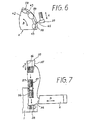
- Fig. 7 shows the elements for length adjustment in an exploded view.
- the cutting insert in the form of an indexable insert 3 and the receiving piece 4 receiving the indexable insert 3.
- the indexable insert 3 has two cover or support surfaces 10 arranged parallel to one another and is formed with nine main corners - with three main corners - and has main cutting edges 11 and secondary cutting edges 12.
- the main cutting edge 11 and secondary cutting edge 12, which are in engagement with the round material R to be peeled, ge - The intersection formed is designated 13.
- the base body 1 has a wide front part 21 with a support surface 22 for the receiving piece 4.
- the support surface 22 has an annular elevation 23 and is closed off by a hollow cylindrical wall 24 arranged concentrically therewith. Both the center point of the annular elevation 23 and the center point or the axis of the hollow cylindrical wall 24 are identical to the intersection point 13 of the main and secondary cutting edges 11 and 12 or go through it.
- the front part 21 has, at a short distance from the hollow cylindrical wall 24, a recess provided with a threaded bore 25 and a hollow cylindrical extension 26.
- the base body 1 At its end facing away from the bearing surface 22, the base body 1 has a groove 28 for guiding the setting piece 2, which - apart from a slight clearance fit - corresponds to the dimensions of the setting piece.
- the (imaginary) central plane 29 of the groove 28 runs through the secondary cutting edge 12 of the indexable insert 3 that is in use.
- a support surface 30 arranged on the base body runs perpendicular to the groove. Between this support surface 30 and the groove 28 there is an intermediate space 31 in which a wedge 33 with a threaded bore 34 is located.
- the threaded hole 34 of the wedge 33 there is one end 57 of a double threaded pin 37, which is inserted with its other end 56 into a threaded hole 38 of the base body 1. While the threaded hole 38 and the associated end 56 of the double-threaded screw 37 have a normal thread with the pitch s, the threaded hole 34 of the wedge 33 and the associated end 57 of the double-threaded pin 37 are provided with a fine thread with a smaller pitch s'. With a clockwise rotation of the double threaded pin 37 of 360, the wedge 33 is thus only moved downward by the sliding path (s-s').
- the wedge 33 thus enables a very fine adjustment of the holder and thus the secondary cutting edge 12 in the radial direction.
- the adjusting piece 2 is attached to the base body 1 using a cap screw 39 held. In order to allow a displacement of the adjusting piece 2, an elongated hole 40 is provided for the head screw 39 in the base body 1.
- the receiving piece 4 has a support or support surface 42 corresponding to the support surface 22 with a corresponding annular groove 43 and a cylindrical wall 44 corresponding to the hollow cylindrical wall 24.
- the receptacle 4 On its upper side, the receptacle 4 has a recess 46, the contour 47 of which corresponds to part of the outer contour of the indexable insert 3.
- the receptacle 4 is held on the base body 1 by two cap screws 48, the receptacle 4 being provided with recesses or recesses 49 on its upper side for supporting the heads of the screws 48.
- the through holes 58 provided in the receptacle 4 for the screws are designed as elongated holes in order to be able to perform a pivoting movement of the receptacle 4 relative to the base body 1.
- a head screw 50 which has its threaded part in the threaded bore 25 and whose head engages in the recess 45 of the receiving piece 4, serves to pivot the receiving piece 4 and the indexable insert 3.
- a rotation of the cap screw 50 by 10 corresponds to the change in the angular position of the minor cutting edge 12 of only 2.7 angular minutes (').
- a claw 51 is provided, which is screwed on with a threaded pin 52 with right and left hand threads Take piece 4 is clamped and is supported with its end facing away from the insert 3 on the base body 1.
- the through hole 59 provided in the receptacle 4 for the threaded pin 52 is designed as an elongated hole in order to allow the receptacle 4 to pivot relative to the base body 1. Due to the right and left hand threads of the set screw 52, the claw 51 is lifted off the indexable insert quickly and safely when it is loosened.
Abstract
Das Schälwerkzeug besteht im wesentlichen aus einem Halter mit Grundkörper (1) und Einstellstück (2), aus einem Schneideinsatz (3) mit Haupt- und Nebenschneiden (11, 12) und aus einem Aufnahmestück (4) für den Schneideinsatz (3). Das Aufnahmestück ist um den Schnittpunkt (13) der am zu schälenden Rundmaterial R im Eingriff befindlichen Haupt- (11) und Nebenschneide (12) schwenkbar auf dem Grundkörper (1) gelagert. Zum Verschwenken dient eine mit ihrem Gewindeteil im Grundkörper (1) befindliche Kopfschraube (50), die mit ihrem Kopf in eine Ausnehmung (45) des Aufnahmestücks (4) eingreift. Das Einstellstück (2) - und mit ihm die Länge des ganzen Halters - wird mit Hilfe eines Keiles (33) verändert.The peeling tool essentially consists of a holder with base body (1) and adjusting piece (2), a cutting insert (3) with main and secondary cutting edges (11, 12) and a receiving piece (4) for the cutting insert (3). The receptacle is pivotally mounted on the base body (1) about the intersection (13) of the main cutting edge (11) and secondary cutting edge (12) which is in engagement with the round material R to be peeled. A head screw (50) with its threaded part in the base body (1) is used for pivoting, and its head engages in a recess (45) in the receiving piece (4). The adjusting piece (2) - and with it the length of the whole holder - is changed with the help of a wedge (33).
Description
Die Erfindung betrifft ein Werkzeug mit einem Halter und einem Schneideinsatz für den umlaufenden Messerkopf einer Schälmaschine zum Schälen von Rundmaterial, wie Rohren,Rundstahl od. dgl., wobei der Schneideinsatz mindestens je eine Haupt- und eine Nebenschneide aufweist.The invention relates to a tool with a holder and a cutting insert for the rotating cutter head of a peeling machine for peeling round material, such as pipes, round steel or the like. The cutting insert has at least one main and one secondary cutting edge.
Im allgemeinen sind vier solcher Werkzeuge im umlaufenden Messerkopf einer Schälmaschine angeordnet. Dabei sollen sich die Schneidkräfte zwischen den Werkzeugen und dem zu schälenden Rundmaterial möglichst symmetrisch ergeben, damit weder auf den Werkzeugkopf noch auf das Rundmaterial Biegemomente ausgeübt werden, die die gewünschte Fertigungsgenauigkeit des geschälten Rundmaterials beeinträchtigen. Dazu müssen insbesondere die Nebenschneiden genau parallel zur Mittelachse des Rundmaterials ausgerichtet sein.In general, four such tools are arranged in the rotating cutter head of a peeling machine. The cutting forces between the tools and the round material to be peeled should result as symmetrically as possible so that bending moments are not exerted on the tool head or on the round material, which impair the desired manufacturing accuracy of the peeled round material. For this purpose, in particular the minor cutting edges must be aligned exactly parallel to the central axis of the round material.
Bei einem bekannten Schälwerkzeug ist eine mit je zweimal zwei Haupt- und Nebenschneiden versehene Wendeschneidplatte in einer entsprechenden Ausnehmung eines Halters eingelassen und mit einer Pratze oder Spannklaue am Halter befestigt. Der Halter selber ist im wesentlichen zweiteilig aus einem Grundkörper mit einer Längsnut und aus einem darin verschiebbaren Stellteil, dessen Lage relativ zum Grundkörper mit einer Stiftschraube eingestellt und mit Hilfe einer durch ein im Grundkörper befindliches Langloch gehenden Klemmschraube fixiert werden kann, ausgebildet.In a known peeling tool, an indexable insert, each provided with two main and secondary cutting edges, is inserted in a corresponding recess in a holder and fastened to the holder with a claw or clamping claw. The holder itself is essentially in two parts made up of a base body with a longitudinal groove and an actuating part which can be displaced therein, the position of which is adjusted relative to the base body with a stud screw and fixed with the aid of a clamping screw passing through an elongated hole in the base body can be trained.
Aus wirtschaftlichen Gründen können der Halter und die Wendeschneidplatte nicht beliebig genau gefertigt werden. Da sich Maßabweichungen addieren können, kann sich bei dem bekannten Werkzeug eine ungünstige Winkelstellung der Nebenschneide einstellen. Eine solche ungünstige Winkellage kann dadurch korrigiert werden, daß die am Halter befestigte Wendeschneidplatte nachgeschliffen wird. Dies führt aber wiederum zu unerwünschten Standzeiteinbußen.For economic reasons, the holder and the indexable insert cannot be manufactured with as much precision as required. Since dimensional deviations can add up, an unfavorable angular position of the minor cutting edge can occur in the known tool. Such an unfavorable angular position can be corrected by grinding the indexable insert attached to the holder. However, this in turn leads to undesirable losses in service life.
Bei einem Schälwerkzeug mit konvex ausgebildeter Schneide ist eine Winkelverstellung des Halters bekannt, die um den Mittelpunkt der kreisbogenförmigen Schneide erfolgt (vgl. z. B. DE-OS 30 08 547). Eine solche Verstellung vermag aber bei Werkzeugen mit geraden Haupt-und Nebenschneiden keine Abhilfe zu schaffen, da dabei auch die Hauptschneide in axialer Richtung des zu schälenden Rundmaterials verstellt würde, wodurch gegenüber den anderen an dem Messerkopf befindlichen Werkzeugen an dieser Stelle ein dickerer - oder dünnerer - Span erzeugt wird, der die erwünschte symmetrische Kräfteverteilung stören würde.In the case of a peeling tool with a convex cutting edge, an angular adjustment of the holder is known, which takes place around the center of the circular cutting edge (see, for example, DE-OS 30 08 547). However, such an adjustment cannot provide any remedy for tools with straight main and secondary cutting edges, since the main cutting edge would also be adjusted in the axial direction of the round material to be peeled, as a result of which a thicker - or thinner - at this point compared to the other tools located on the cutter head - Chip is generated that would interfere with the desired symmetrical distribution of forces.
Weiterhin ist aus der DE-PS 22 10 816 ein Wellenschälwerkzeug bekannt, bei dem ein mit zweimal zwei Haupt-und Nebenschneiden versehener Wendeschneidkörper in einer entsprechenden Ausnehmung des Halters angeordnet und von einem Stellkeil in seiner Winkellage einstellbar ist. Beim Nachstellen der Winkellage der Nebenschneide wird der Wendeschneidkörper im wesentlichen um seine von der im Einsatz befindlichen Hauptschneide abgewandten Stirnseite geschwenkt, wodurch der von der dem zu schälenden Material zugewandten Haupt- und Nebenschneide gebildete Schnittpunkt eine Bewegung radial zum Rundmaterial vollzieht. Bei diesem bekannten Werkzeug kann es daher notwendig sein, nach der Winkeleinstellung der Nebenschneide auch noch einmal die radiale Einstellung des ganzen Werkzeugs nachzujustieren. Weiterhin ist an diesem bekannten Werkzeug nachteilig, daß es je nach der eingestellten Winkellage des Wendeschneidkörpers zumindest an einer Stelle zwischen der oben bezeichneten Stirnseite des Wendeschneidkörpers und der entsprechenden Aufnahme im Halter zu einer linienförmigen Belastung kommen kann.Furthermore, a shaft peeling tool is known from DE-PS 22 10 816, in which an indexable cutting body provided with two main and secondary cutting edges is arranged in a corresponding recess in the holder and its angular position can be adjusted by an adjusting wedge. When adjusting the angular position of the secondary cutting edge, the indexable cutting body is pivoted essentially around its end face facing away from the main cutting edge in use, as a result of which the intersection point formed by the main and secondary cutting edge facing the material to be peeled executes a movement radially to the round material. With this Known tool, it may therefore be necessary to readjust the radial setting of the entire tool again after adjusting the angle of the secondary cutting edge. A further disadvantage of this known tool is that, depending on the set angular position of the indexable cutting body, a linear load can occur at least at one point between the end face of the indexable cutting body described above and the corresponding receptacle in the holder.
Der Erfindung liegt die Aufgabe zugrunde, ein Schälwerkzeug mit mindestens einer Haupt- und Nebenschneide anzugeben, bei dem - bei gleicher Dicke des von der Hauptschneide eines jeden im Messerkopf angeordneten Schälwerkzeugs erzeugten Spans - eine genaue Parallelstellung der Nebenschneide zur Mittelachse des zu schälenden Rundmaterials - bzw. eine genaue Rechtwinkligkeit zur Rückseite des Halters - erreichbar ist, ohne die Nebenschneide nachschleifen oder das ganze Werkzeug radial nachjustieren zu müssen. Dabei soll auch eine feinfühlige Einstellung des ganzen Werkzeugs in radialer Richtung möglich sein.The invention has for its object to provide a peeling tool with at least one main and secondary cutting edge, in which - with the same thickness of the chip produced by the main cutting edge of each peeling tool arranged in the cutter head - an exact parallel position of the secondary cutting edge to the central axis of the round material to be peeled - or an exact perpendicularity to the rear of the holder can be achieved without having to regrind the secondary cutting edge or to readjust the entire tool radially. It should also be possible to fine-tune the entire tool in the radial direction.
Diese Aufgabe wird durch die im Anspruch 1 gekennzeichneten Merkmale gelöst. Durch die Schwenkbarkeit des Aufnahmestückes kann die Winkligkeit der Nebenschneide ohne Vor- oder Nachschleifen beliebig eingestellt werden. Dadurch, daß der Schwenkmittelpunkt mit dem Schnittpunkt der Haupt- und Nebenschneide zusammenfällt, wird die Lage der Hauptschneide insbesondere in axialer Richtung des zu schälenden Materials betrachtet,nicht verändert.This object is achieved by the features characterized in
Die Ausbildung des Werkzeuges nach Anspruch 2 stellt eine besonders einfache Ausführungsform des Schwenklagers dar.The design of the tool according to
Obwohl eine Einstellung der Winkellage der Nebenschneide beliebig erfolgen kann, ist es vorteilhaft,das Werkzeug mit einer Verstelleinrichtung nach Anspruch 3 auszurüsten, wobei mit den Merkmalen des Anspruchs 4 eine besonders vorteilhafte Lösung aufgezeigt ist.Although the angular position of the secondary cutting edge can be set as desired, it is advantageous to equip the tool with an adjusting device according to
Mit der Ausbildung des Werkzeugs nach Anspruch 5 kann die Nebenschneide in radialer Richtung besonders feinfühlig eingestellt werden.With the design of the tool according to claim 5, the secondary cutting edge can be adjusted particularly sensitively in the radial direction.
Ein Ausführungsbeispiel des Gegenstandes der Erfindung ist in der Zeichnung dargestellt und wird im folgenden näher beschrieben. Es zeigen:
- Fig. 1 das Werkzeug in der Draufsicht auf den Schneideinsatz,
- Fig. 2 das Werkzeug in einer Seitenansicht gemäß der Blickrichtung II in Fig. 1 mit Blick auf die Längsnut des Grundkörpers und auf das Einstellstück,
- Fig. 3 das Werkzeug in einem Querschnitt längs der Linie III-III in Fig. 2,
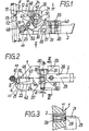
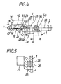
- Fig. 4 das Werkzeug in einer Seitenansicht gemäß der Blickrichtung IV in Fig. 1,
- Fig. 5 das Werkzeug in einem Querschnitt längs der Linie V-V in Fig. 4,
- Fig. 6 die Unterseite oder Auflagefläche des Aufnahmestücks für die Wendeschneidplatte und die zugehörige Stellschraube in einer
- 1 the tool in plan view of the cutting insert,
- 2 the tool in a side view according to viewing direction II in FIG. 1 with a view of the longitudinal groove of the base body and of the adjusting piece,
- 3 shows the tool in a cross section along the line III-III in FIG. 2,
- 4 the tool in a side view according to the viewing direction IV in FIG. 1,
- 5 shows the tool in a cross section along the line VV in FIG. 4,
- Fig. 6 shows the underside or contact surface of the receiving piece for the indexable insert and the associated set screw in one
Fig. 7 die Elemente zur Längeneinstellung in einer Explosionsdarstellung.Fig. 7 shows the elements for length adjustment in an exploded view.
In den Fig. 2 und 5 ist die Pratze der Einfachheit halber weggelassen.2 and 5, the claw is omitted for the sake of simplicity.
Das Schälwerkzeug nach Fig. 1 besteht aus einem Halter mit einem Grundkörper 1 und einem Einstellstück 2, dem Schneideinsatz in Form einer Wendeschneidplatte 3 und dem die Wendeschneidplatte 3 aufnehmenden Aufnahmestück 4.1 consists of a holder with a
Die Wendeschneidplatte 3 weist zwei parallel zueinander angeordnete Deck- bzw. Auflageflächen 10 auf und ist - mit drei Hauptecken - neuneckig ausgebildet und besitzt Hauptschneiden 11 und Nebenschneiden 12. Der von der jeweils am zu schälenden Rundmaterial R im Eingriff befindlichen Hauptschneide 11 und Nebenschneide 12 ge- bildete Schnittpunkt ist mit 13 bezeichnet.The
Der Grundkörper 1 besitzt einen breiten vorderen Teil 21 mit einer Auflagefläche 22 für das Aufnahmestück 4. Die Auflagefläche 22 weist eine kreisringförmige Erhebung 23 auf und ist durch eine dazu konzentrisch angeordnete hohlzylindrische Wandung 24 abgeschlossen. Sowohl der Mittelpunkt der kreisringförmigen Erhebung 23 als auch der Mittelpunkt bzw. die Achse der hohlzylindrischen Wandung 24 sind identisch mit dem Schnittpunkt 13 der Haupt- und Nebenschneide 11 und 12 bzw. gehen durch diesen hindurch.The
Der vordere Teil 21 weist in einem geringen Abstand zu der hohlzylindrischen Wandung 24 eine mit einer Gewindebohrung 25 und einer hohlzylindrischen Erweiterung 26 versehene Ausnehmung auf.The
An seinem von der Auflagefläche 22 wegweisenden Ende weist der Grundkörper 1 zur Führung des Einstellstücks 2 eine Nut 28 auf, die - abgesehen von einer geringen Spielpassung - den Abmessungen des Einstellstücks entspricht. Dabei verläuft die (gedachte) Mittelebene 29 der Nut 28 durch die im Einsatz befindliche Nebenschneide 12 der Wendeschneidplatte 3. Senkrecht zur Nut verläuft eine am Grundkörper angeordnete Stützfläche 30. Zwischen dieser Stützfläche 30 und der Nut 28 ist ein Zwischenraum 31 angeordnet, in dem sich ein Keil 33 mit einer Gewindebohrung 34 befindet. Die von der Stützfläche 30 wegweisende geneigte Fläche 35 des Keiles 33 drückt gegen die vordere, der Wendeschneidplatte 3 zugewandte Stirnfläche 36 des Einstellstücks 2, das die gleiche Neigung wie der Keil von z.B. a = 10 aufweist.At its end facing away from the
In dem Gewindeloch 34 des Keiles 33 befindet sich das eine Ende 57 eines Doppelgewindestiftes 37, die mit ihrem anderen Ende 56 in einem Gewindeloch 38 des Grundkörpers 1 steckt. Während das Gewindeloch 38 und das zugehörige Ende 56 der Doppelgewindeschraube 37 ein Normalgewinde mit der Steigung s aufweist, ist das Gewindeloch 34 des Keiles 33 und das zugehörige Ende 57 des Doppelgewindestiftes 37 mit Feingewinde mit einer geringeren Steigung s' versehen. Bei einer Rechtsdrehung des Doppelgewindestiftes 37 von 360 wird der Keil 33 somit nur um den Gleitweg (s - s') nach unten bewegt. Durch die flache Neigung der Keilfläche 35 und der Stirnfläche 36 wird das Einstellstück 2 dabei nur um den Weg (s - s') x tana bewegt. Ist beispielsweise die Steigung s = 1,25 mm, die Steigung s' =O75 mm und der Winkel a = 10 , so entspricht eine Umdrehung des Doppelgewindestiftes 37 einem Gleitweg des Einzelstücks 2 von nur knapp 9/100 mm. Der Keil 33 ermöglicht also eine sehr feine Einstellung des Halters und damit der Nebenschneide 12 in radialer Richtung. Das Einstellstück 2 wird mit Hilfe einer Kopfschraube 39 am Grundkörper 1 gehalten. Um eine Verschiebung des Einstellstücks 2 zu ermöglichen, ist für die Kopfschraube 39 im Grundkörper 1 ein Langloch 40 vorgesehen.In the threaded
Das Aufnahmestück 4 weist eine der Auflagefläche 22 entsprechende Auflage- oder Stützfläche 42 mit einer entsprechenden ringförmigen Nut 43 und eine der hohlzylindrischen Wandung 24 entsprechende zylindrische Wandung 44 auf. Der Mittelpunkt bzw. die Achse der Vertiefung oder Nut 43 und der Wandung 44, in die eine Ausnehmung oder Vertiefung 45 eingelassen ist, gehen - wie beim Grundkörper 1 - durch den Schnittpunkt 13 der Hauptschneide 11 und der Nebenschneide 12 des Werkzeuges.The
An seiner Oberseite weist das Aufnahmestück 4 eine Ausnehmung 46 auf, deren Kontur 47 einem Teil der Außenkontur der Wendeschneidplatte 3 entspricht. Das Aufnahmestück 4 wird durch zwei Kopfschrauben 48 am Grundkörper 1 festgehalten, wobei das Aufnahmestück 4 zur Auflage der Köpfe der Schrauben 48 an seiner Oberseite mit Vertiefungen bzw. Ausnehmungen 49 versehen ist. Die im Aufnahmestück 4 für die Schrauben vorgesehenen Durchgangslöcher 58 sind als Langlöcher ausgebildet, um eine Schwenkbewegung des Aufnahmestücks 4 gegenüber dem Grundkörper 1 ausführen zu können. Zum Verschwenken des Aufnahmestücks 4 und der Wendeschneidplatte 3 dient eine Kopfschraube 50, die mit ihrem Gewindeteil in der Gewindebohrung 25 ist, und deren Kopf in die Ausnehmung 45 des Aufnahmestücks 4 eingreift. Bei einer Steigung des Gewindeteils der Kopfschraube 50 von beispielsweise s = 1 mm und bei einem angenommenen Radius der Außenwandung 44 von 36 mm entspricht eine Drehung der Kopfschraube 50 um 10 der Änderung der Winkellage der Nebenschneide 12 von nur 2,7 Winkelminuten (').On its upper side, the
Zur Befestigung der Wendeschneidplatte 3 auf dem Werkzeug ist eine Pratze 51 vorgesehen, die mit Hilfe eines Gewindestiftes 52 mit Rechts- und Linksgewinde am Aufnahmestück 4 verspannt ist und die sich mit ihrem der Wendeschneidplatte 3 abgewandten Ende am Grundkörper 1 abstützt. Das im Aufnahmestück 4 für den Gewindestift 52 vorgesehene Durchgangsloch 59 ist als Langloch ausgebildet, um eine Schwenkbewegung des Aufnahmestücks 4 gegenüber dem Grundkörper 1 zu ermöglichen. Durch die Rechts- und Linksgewinde des Gewindestiftes 52 wird die Pratze 51 beim Lösen schnell und sicher von der Wendeschneidplatte abgehoben.To attach the
Claims (5)
wobei der Schneideinsatz mindestens
je eine Haupt- und eine Nebenschneide aufweist, dadurch gekennzeichnet,
the cutting insert at least
each has a major and a minor cutting edge, characterized in that
dadurch gekennzeichnet,
daß das vom Halter (1) und dem Aufnahmestück (4) gebildete Schwenklager
characterized,
that the pivot bearing formed by the holder (1) and the receiving piece (4)
dadurch gekennzeichnet,
daß die Verstelleinrichtung durch eine Kopfschraube (50) gebildet wird, die mit ihrem Gewindeteil in eine im Halter (1) befindliche Gewindebohrung (25) und mit ihrem Kopf in eine Ausnehmung (45) am Aufnahmestück (4) eingreift.4. Tool according to claim 3,
characterized,
that the adjusting device is formed by a cap screw (50) which engages with its threaded part in a threaded bore (25) located in the holder (1) and with its head in a recess (45) on the receiving piece (4).
Applications Claiming Priority (2)
| Application Number | Priority Date | Filing Date | Title |
|---|---|---|---|
| DE3325286 | 1983-07-13 | ||
| DE3325286 | 1983-07-13 |
Publications (2)
| Publication Number | Publication Date |
|---|---|
| EP0131784A1 true EP0131784A1 (en) | 1985-01-23 |
| EP0131784B1 EP0131784B1 (en) | 1986-09-24 |
Family
ID=6203887
Family Applications (1)
| Application Number | Title | Priority Date | Filing Date |
|---|---|---|---|
| EP84107142A Expired EP0131784B1 (en) | 1983-07-13 | 1984-06-22 | Peeling tool |
Country Status (5)
| Country | Link |
|---|---|
| US (1) | US4631994A (en) |
| EP (1) | EP0131784B1 (en) |
| JP (1) | JPS6039003A (en) |
| DE (1) | DE3460816D1 (en) |
| IN (1) | IN159490B (en) |
Cited By (3)
| Publication number | Priority date | Publication date | Assignee | Title |
|---|---|---|---|---|
| US5256008A (en) * | 1991-03-04 | 1993-10-26 | Sandvik Ab | Cutting tool for a peeling operation |
| WO1993024264A1 (en) * | 1992-05-25 | 1993-12-09 | Sandvik Ab | Adjustable cutting tool holder for a peeling operation |
| WO1994029053A1 (en) * | 1993-06-11 | 1994-12-22 | Sandvik Ab | Adjustable cutting tool for a peeling operation |
Families Citing this family (22)
| Publication number | Priority date | Publication date | Assignee | Title |
|---|---|---|---|---|
| US4927301A (en) * | 1988-12-27 | 1990-05-22 | Gte Valenite Corporation | Adjustable boring bar cartridge |
| US5090280A (en) * | 1990-03-21 | 1992-02-25 | Kennametal Inc. | Tool holder assembly with angular adjustment mechanism |
| US5147157A (en) * | 1991-08-07 | 1992-09-15 | Gte Valenite Corporation | Adjustable leaf spring cartridge for face mills |
| US5156501A (en) * | 1991-08-07 | 1992-10-20 | Gte Valenite Corporation | Adjustable torsion bar cartridge for face mills |
| US5193421A (en) * | 1992-06-16 | 1993-03-16 | Atwood Industries, Inc. | System and method for presetting tooling |
| US5336026A (en) * | 1992-12-21 | 1994-08-09 | Valenite Inc. | Adjustable boring bar |
| US5320458A (en) * | 1993-05-24 | 1994-06-14 | Valenite Inc. | Cutting tool having a cutter cartridge adjustable around two adjustment axes |
| US6190096B1 (en) | 1996-08-07 | 2001-02-20 | Kennametal Inc. | Indexable cutting insert with indexing marks |
| SE509306C2 (en) * | 1998-04-29 | 1999-01-11 | Sandvik Ab | Cutter for cranking |
| US6082234A (en) * | 1998-06-25 | 2000-07-04 | Peterson Tool Company | Adjustable toolholder |
| US6295905B1 (en) | 1998-12-18 | 2001-10-02 | Peterson Tool Company | Toolholder with a removable head |
| US7114890B2 (en) | 2001-02-13 | 2006-10-03 | Valenite Inc. | Cutting tool adjustment device |
| IL160767A0 (en) * | 2004-03-07 | 2004-08-31 | Shilo Technologies Ltd | Tool for repairing damaged screw threads |
| SE528820C2 (en) * | 2004-12-14 | 2007-02-20 | Seco Tools Ab | Drilling tool with adjustable cassette |
| ES2561096T3 (en) * | 2011-11-04 | 2016-02-24 | Walter Ag | Cartridge with coarse adjustment means and fine adjustment means |
| US9205499B2 (en) | 2013-09-11 | 2015-12-08 | Kennametal Inc. | Cutting insert with finishing and roughing cutting edges |
| US9211590B2 (en) | 2013-09-20 | 2015-12-15 | Kennametal Inc. | Screw head wedge clamp assembly for cutting tool |
| US9211589B2 (en) | 2013-10-08 | 2015-12-15 | Kennametal Inc. | Double-sided, nonagon cutting insert |
| DE102014100483B4 (en) * | 2014-01-16 | 2016-12-08 | Kennametal Inc. | Cassette for cutting insert |
| US9475138B2 (en) | 2014-01-22 | 2016-10-25 | Kennametal Inc. | Cutting tool having insert pocket with cantilevered member |
| EP3144086B1 (en) * | 2015-09-15 | 2018-05-09 | Sandvik Intellectual Property AB | A tool body and a turning tool for grooving operations |
| JP6710672B2 (en) * | 2017-11-13 | 2020-06-17 | 東芝三菱電機産業システム株式会社 | Processing tool for cutting |
Citations (5)
| Publication number | Priority date | Publication date | Assignee | Title |
|---|---|---|---|---|
| DE1941982A1 (en) * | 1968-08-19 | 1970-02-26 | Saginaw Machine & Tool Co | Tool holder |
| US3683473A (en) * | 1969-03-04 | 1972-08-15 | Wickman Wimet Ltd | Toolholders with detachable cutting inserts |
| DE2506902B2 (en) * | 1975-02-19 | 1977-05-26 | TURNING TOOL WITH REPLACEABLE, MULTI-RECTANGULAR CUTTING INSERT | |
| DE3001330A1 (en) * | 1980-01-16 | 1981-07-23 | Komet Stahlhalter- Und Werkzeugfabrik Robert Breuning Gmbh, 7122 Besigheim | Lathe cutting bit carrier - has part cylindrical periphery and polygonal recess with central screw bore for fitting bit by clamp screw |
| DE3008547A1 (en) * | 1980-03-06 | 1981-09-10 | Lindemann, Wolfgang, Dipl.-Phys. Dr.-Ing., 4800 Bielefeld | Bar descaling machine rotary cutter head - has blades guided to keep edge distance from work axis constant |
Family Cites Families (10)
| Publication number | Priority date | Publication date | Assignee | Title |
|---|---|---|---|---|
| DE657995C (en) * | 1936-11-14 | 1938-03-18 | Winter & Sohn Ernst | Adjustable fastening of diamond tools in boring bars |
| DE709871C (en) * | 1937-09-07 | 1941-08-28 | Paul Stein | Steel holding tool for machine tools |
| US2368736A (en) * | 1940-08-24 | 1945-02-06 | Clayton E Wyrick | Turret toolholder |
| US3253322A (en) * | 1963-06-06 | 1966-05-31 | Brown Mclaren Mfg Co | Form tool |
| US3500523A (en) * | 1967-08-14 | 1970-03-17 | Saginaw Machine & Tool Co | Tool holder construction |
| US3498164A (en) * | 1968-03-14 | 1970-03-03 | Bullard Co | Adjustable tool support |
| US3755868A (en) * | 1971-07-23 | 1973-09-04 | Gen Electric | Adjustable cutting tool |
| BE794309A (en) * | 1972-03-07 | 1973-05-16 | Hertel Karl | TOOL TO NIP TREES BY REMOVING CHIPS |
| DE2424790A1 (en) * | 1974-05-22 | 1975-12-11 | Ass Eng Ltd | Sintered polygonal cutter bit - mounted on holder with angular adjustment |
| CH600977A5 (en) * | 1975-11-27 | 1978-06-30 | Stellram Sa | Angularly adjustable cutting tool for lathe |
-
1984
- 1984-06-22 EP EP84107142A patent/EP0131784B1/en not_active Expired
- 1984-06-22 US US06/623,433 patent/US4631994A/en not_active Expired - Fee Related
- 1984-06-22 DE DE8484107142T patent/DE3460816D1/en not_active Expired
- 1984-06-25 IN IN443/CAL/84A patent/IN159490B/en unknown
- 1984-07-12 JP JP59143417A patent/JPS6039003A/en active Pending
Patent Citations (5)
| Publication number | Priority date | Publication date | Assignee | Title |
|---|---|---|---|---|
| DE1941982A1 (en) * | 1968-08-19 | 1970-02-26 | Saginaw Machine & Tool Co | Tool holder |
| US3683473A (en) * | 1969-03-04 | 1972-08-15 | Wickman Wimet Ltd | Toolholders with detachable cutting inserts |
| DE2506902B2 (en) * | 1975-02-19 | 1977-05-26 | TURNING TOOL WITH REPLACEABLE, MULTI-RECTANGULAR CUTTING INSERT | |
| DE3001330A1 (en) * | 1980-01-16 | 1981-07-23 | Komet Stahlhalter- Und Werkzeugfabrik Robert Breuning Gmbh, 7122 Besigheim | Lathe cutting bit carrier - has part cylindrical periphery and polygonal recess with central screw bore for fitting bit by clamp screw |
| DE3008547A1 (en) * | 1980-03-06 | 1981-09-10 | Lindemann, Wolfgang, Dipl.-Phys. Dr.-Ing., 4800 Bielefeld | Bar descaling machine rotary cutter head - has blades guided to keep edge distance from work axis constant |
Cited By (4)
| Publication number | Priority date | Publication date | Assignee | Title |
|---|---|---|---|---|
| US5256008A (en) * | 1991-03-04 | 1993-10-26 | Sandvik Ab | Cutting tool for a peeling operation |
| WO1993024264A1 (en) * | 1992-05-25 | 1993-12-09 | Sandvik Ab | Adjustable cutting tool holder for a peeling operation |
| WO1994029053A1 (en) * | 1993-06-11 | 1994-12-22 | Sandvik Ab | Adjustable cutting tool for a peeling operation |
| US5564320A (en) * | 1993-06-11 | 1996-10-15 | Sandvik Ab | Cutting tool for a bar peeling operation |
Also Published As
| Publication number | Publication date |
|---|---|
| EP0131784B1 (en) | 1986-09-24 |
| IN159490B (en) | 1987-05-23 |
| JPS6039003A (en) | 1985-02-28 |
| DE3460816D1 (en) | 1986-10-30 |
| US4631994A (en) | 1986-12-30 |
Similar Documents
| Publication | Publication Date | Title |
|---|---|---|
| EP0131784B1 (en) | Peeling tool | |
| DE2339873C2 (en) | Arrangement for setting and securing a block carrying a cutting tip in a groove-shaped receptacle in the tool body of a cutting tool | |
| DE3715338A1 (en) | FAST-ROTATING MILL OR DRILL HEAD | |
| EP0182290A2 (en) | Milling cutter head | |
| EP0385280A1 (en) | Inside turning tool | |
| EP0085156B2 (en) | Reaming tool with one cutting insert | |
| DE3031216A1 (en) | CHUCK FOR TAPS. | |
| EP0523404B1 (en) | Tool for milling and drilling with two cutting edges | |
| DE7812666U1 (en) | DRILLING TOOL | |
| EP0217035A1 (en) | Cutter head | |
| EP0129116A2 (en) | Tool for forward and backward milling | |
| DE1502125B1 (en) | Cutter head for square indexable inserts | |
| DE3738000A1 (en) | Drilling tool | |
| EP0143870A1 (en) | Auxiliary device for sharpening twist drills | |
| DE2320876A1 (en) | BORING HEAD | |
| DE1502083A1 (en) | Improvements to cutters | |
| DE2931508A1 (en) | Adjustable boring tool assembly - has two diametrically opposed cutting edges moving in or out simultaneously | |
| DE3220363A1 (en) | CUTTING KNIFE CARRIER FOR ROUGHING METALLIC SURFACES | |
| DE3205202A1 (en) | Guide arrangement for working with a power unit | |
| DE8320202U1 (en) | SCHAEL TOOL | |
| EP0606086A1 (en) | Cassette for securing a cutting insert onto a milling tool | |
| DE3509161C2 (en) | ||
| EP0470285B1 (en) | Cutting tool for the machining of internal and external shapes on workpieces | |
| DE3432615C2 (en) | ||
| DE2649570C2 (en) | Device for guiding a tool holding device |
Legal Events
| Date | Code | Title | Description |
|---|---|---|---|
| PUAI | Public reference made under article 153(3) epc to a published international application that has entered the european phase |
Free format text: ORIGINAL CODE: 0009012 |
|
| AK | Designated contracting states |
Designated state(s): DE FR GB SE |
|
| 17P | Request for examination filed |
Effective date: 19841212 |
|
| GRAA | (expected) grant |
Free format text: ORIGINAL CODE: 0009210 |
|
| AK | Designated contracting states |
Kind code of ref document: B1 Designated state(s): DE FR GB SE |
|
| REF | Corresponds to: |
Ref document number: 3460816 Country of ref document: DE Date of ref document: 19861030 |
|
| ET | Fr: translation filed | ||
| PLBE | No opposition filed within time limit |
Free format text: ORIGINAL CODE: 0009261 |
|
| STAA | Information on the status of an ep patent application or granted ep patent |
Free format text: STATUS: NO OPPOSITION FILED WITHIN TIME LIMIT |
|
| 26N | No opposition filed | ||
| PGFP | Annual fee paid to national office [announced via postgrant information from national office to epo] |
Ref country code: SE Payment date: 19890529 Year of fee payment: 6 |
|
| PGFP | Annual fee paid to national office [announced via postgrant information from national office to epo] |
Ref country code: GB Payment date: 19890531 Year of fee payment: 6 |
|
| PGFP | Annual fee paid to national office [announced via postgrant information from national office to epo] |
Ref country code: DE Payment date: 19890623 Year of fee payment: 6 |
|
| PGFP | Annual fee paid to national office [announced via postgrant information from national office to epo] |
Ref country code: FR Payment date: 19890626 Year of fee payment: 6 |
|
| PG25 | Lapsed in a contracting state [announced via postgrant information from national office to epo] |
Ref country code: GB Effective date: 19900622 |
|
| PG25 | Lapsed in a contracting state [announced via postgrant information from national office to epo] |
Ref country code: SE Effective date: 19900623 |
|
| GBPC | Gb: european patent ceased through non-payment of renewal fee | ||
| PG25 | Lapsed in a contracting state [announced via postgrant information from national office to epo] |
Ref country code: FR Effective date: 19910228 |
|
| PG25 | Lapsed in a contracting state [announced via postgrant information from national office to epo] |
Ref country code: DE Effective date: 19910301 |
|
| REG | Reference to a national code |
Ref country code: FR Ref legal event code: ST |
|
| EUG | Se: european patent has lapsed |
Ref document number: 84107142.6 Effective date: 19910206 |