EP0131670A1 - Feed-water preheater with a desuperheater, in particular for a thermal power plant - Google Patents
Feed-water preheater with a desuperheater, in particular for a thermal power plant Download PDFInfo
- Publication number
- EP0131670A1 EP0131670A1 EP83401463A EP83401463A EP0131670A1 EP 0131670 A1 EP0131670 A1 EP 0131670A1 EP 83401463 A EP83401463 A EP 83401463A EP 83401463 A EP83401463 A EP 83401463A EP 0131670 A1 EP0131670 A1 EP 0131670A1
- Authority
- EP
- European Patent Office
- Prior art keywords
- box
- steam
- tubes
- desuperheating
- heater
- Prior art date
- Legal status (The legal status is an assumption and is not a legal conclusion. Google has not performed a legal analysis and makes no representation as to the accuracy of the status listed.)
- Granted
Links
- XLYOFNOQVPJJNP-UHFFFAOYSA-N water Substances O XLYOFNOQVPJJNP-UHFFFAOYSA-N 0.000 title claims abstract description 12
- 230000005494 condensation Effects 0.000 description 5
- 238000009833 condensation Methods 0.000 description 5
- 230000003628 erosive effect Effects 0.000 description 2
- 238000013021 overheating Methods 0.000 description 2
- 230000005540 biological transmission Effects 0.000 description 1
- 230000001143 conditioned effect Effects 0.000 description 1
- 230000000694 effects Effects 0.000 description 1
- 238000010438 heat treatment Methods 0.000 description 1
- 230000004807 localization Effects 0.000 description 1
- 238000005192 partition Methods 0.000 description 1
Images

Classifications
-
- F—MECHANICAL ENGINEERING; LIGHTING; HEATING; WEAPONS; BLASTING
- F28—HEAT EXCHANGE IN GENERAL
- F28F—DETAILS OF HEAT-EXCHANGE AND HEAT-TRANSFER APPARATUS, OF GENERAL APPLICATION
- F28F9/00—Casings; Header boxes; Auxiliary supports for elements; Auxiliary members within casings
- F28F9/22—Arrangements for directing heat-exchange media into successive compartments, e.g. arrangements of guide plates
-
- F—MECHANICAL ENGINEERING; LIGHTING; HEATING; WEAPONS; BLASTING
- F22—STEAM GENERATION
- F22D—PREHEATING, OR ACCUMULATING PREHEATED, FEED-WATER FOR STEAM GENERATION; FEED-WATER SUPPLY FOR STEAM GENERATION; CONTROLLING WATER LEVEL FOR STEAM GENERATION; AUXILIARY DEVICES FOR PROMOTING WATER CIRCULATION WITHIN STEAM BOILERS
- F22D1/00—Feed-water heaters, i.e. economisers or like preheaters
- F22D1/32—Feed-water heaters, i.e. economisers or like preheaters arranged to be heated by steam, e.g. bled from turbines
-
- F—MECHANICAL ENGINEERING; LIGHTING; HEATING; WEAPONS; BLASTING
- F28—HEAT EXCHANGE IN GENERAL
- F28D—HEAT-EXCHANGE APPARATUS, NOT PROVIDED FOR IN ANOTHER SUBCLASS, IN WHICH THE HEAT-EXCHANGE MEDIA DO NOT COME INTO DIRECT CONTACT
- F28D7/00—Heat-exchange apparatus having stationary tubular conduit assemblies for both heat-exchange media, the media being in contact with different sides of a conduit wall
- F28D7/06—Heat-exchange apparatus having stationary tubular conduit assemblies for both heat-exchange media, the media being in contact with different sides of a conduit wall the conduits having a single U-bend
-
- F—MECHANICAL ENGINEERING; LIGHTING; HEATING; WEAPONS; BLASTING
- F28—HEAT EXCHANGE IN GENERAL
- F28F—DETAILS OF HEAT-EXCHANGE AND HEAT-TRANSFER APPARATUS, OF GENERAL APPLICATION
- F28F9/00—Casings; Header boxes; Auxiliary supports for elements; Auxiliary members within casings
- F28F9/007—Auxiliary supports for elements
- F28F9/013—Auxiliary supports for elements for tubes or tube-assemblies
- F28F9/0131—Auxiliary supports for elements for tubes or tube-assemblies formed by plates
Definitions
- the water supplying the boiler passes through a series of heaters generally consisting of a tube bundle, an outer casing and water boxes or collectors.
- the heater (1) represents in Figs. 1 and 2 is a conventional heater. At the upper part of the heater 1 is an inlet 2 for superheated steam. This input is connected to a horizontal desuperheating chamber 3 by means of a distribution box 4. The box is traversed longitudinally by tubes such as 5. Vertical baffles are arranged inside the box 3. These baffles partly used to support the tubes 5.
- the distribution box further comprises an upper horizontal wall 16, a vertical side wall 17 and a flat inclined side wall 18 close to the wall of the casing 11 of the heater and connecting to the horizontal bottom wall 19 of the box 13 via a vertical wall 20.
- These tubes 21 are supported by a series of plates 22 orthogonal to the tubes. These plates are in one piece and have the shape of a rectangle with cut upper corners. These plates occupy the entire cross section of the box 13 with the exception of an area in the vicinity of the walls 18 and 20.
Landscapes
- Engineering & Computer Science (AREA)
- Physics & Mathematics (AREA)
- Thermal Sciences (AREA)
- Mechanical Engineering (AREA)
- General Engineering & Computer Science (AREA)
- Resistance Heating (AREA)
- Water Treatment By Sorption (AREA)
- Beverage Vending Machines With Cups, And Gas Or Electricity Vending Machines (AREA)
- Control Of Resistance Heating (AREA)
- Air Supply (AREA)
- Hydrogen, Water And Hydrids (AREA)
- Beans For Foods Or Fodder (AREA)
- Air-Conditioning For Vehicles (AREA)
- Instantaneous Water Boilers, Portable Hot-Water Supply Apparatuses, And Control Of Portable Hot-Water Supply Apparatuses (AREA)
- Greenhouses (AREA)
Abstract
Description
La présente invention concerne un réchauffeur d'eau alimentaire comprenant une zone de désurchauffe notamment pour centrale électrique thermique.The present invention relates to a food water heater comprising a desuperheating zone, in particular for a thermal electric power station.
Dans une centrale électrique thermique, l'eau alimentant la chaudière passe au travers d'une série de réchauffeurs constitués généralement d'un faisceau tubulaire, d'une enveloppe extérieure et de boîtes à eau ou de collecteurs.In a thermal power plant, the water supplying the boiler passes through a series of heaters generally consisting of a tube bundle, an outer casing and water boxes or collectors.
La vapeur de chauffage pénètre dans l'enveloppe autour du faisceau tubulaire où elle finit par se condenser, cédant sa chaleur à l'eau alimentaire traversant les tubes.The heating steam enters the envelope around the tube bundle where it eventually condenses, giving up its heat to the food water passing through the tubes.
Lorsque la vapeur est surchauffée, le coefficient de transmission de chaleur de la vapeur aux tubes reste fort mauvais jusqu'au point où la condensation de la vapeur débute.When the steam is overheated, the heat transfer coefficient of the steam to the tubes remains very poor up to the point where the condensation of the steam begins.
Pour pallier cette mauvaise transmission de chaleur, il est connu d'augmenter la vitesse de la vapeur en la faisant circuler au travers d'une zone de désurchauffe contenue dans un caisson également traversé par les tubes du réchauffeur et comportant des chicanes servant aussi à supporter des tubes.To overcome this poor heat transmission, it is known to increase the speed of the steam by circulating it through a desuperheating zone contained in a box also crossed by the tubes of the heater and comprising baffles also serving to support tubes.
Ceci est réalisé, toutefois, au prix d'une aug- mentation de la perte de charge qui détériore les performances du réchauffeur et qui est d'autant plus importante que le nombre de chicanes est élevé.Cette perte de charge détermine la différence de pression que le caisson doit pouvoir supporter.This is achieved, however, at the cost of an increase in pressure drop which deteriorates the performance of the heater and which is all the more important as the number of baffles is high. This pressure drop determines the pressure difference that the box must be able to support.
L'entrée et la sortie de la vapeur-dans la zone.de desurchauffe sont des endroits particulièrement délicats car ils sont très localisés et ont une section réduite,ce qui entraîne un impact par la vapeur qui peut être dangereux pour les tubes qui y sont soumis (vibrations,érosion).The entry and exit of steam - in the overheating zone. Are particularly delicate places because they are very localized and have a reduced section, which results in an impact by steam which can be dangerous for the tubes which are there. subject (vibrations, erosion).
La présente invention vise à fournir un réchauffeur d'eau alimentaire comportant une zone de désurchauffe ne présentant pas les inconvénients de la technique antérieure.The present invention aims to provide a food water heater comprising a desuperheating zone which does not have the drawbacks of the prior art.
A cet effet, la présente invention a pour objet un réchauffeur d'eau alimentaire comportant un caisson de désurchauffe de la vapeur traversé longitudinalement par un faisceau de tubes parcourus par l'eau alimentaire, caractérisé en ce que le caisson comprend une entrée de vapeur s'étendant sur au moins une partie substantielle d'une de ses parois latérales.To this end, the subject of the present invention is a food water heater comprising a box for desuperheating steam traversed longitudinally by a bundle of tubes traversed by food water, characterized in that the box comprises a steam inlet s 'extending over at least a substantial part of one of its side walls.
L'entrée de vapeur s'étend avantageusement sur toute la longueur du caisson.The steam inlet advantageously extends over the entire length of the box.
En outre, la sortie de vapeur est avantageusement disposée du côté latéral opposé à l'entrée de vapeur et a une longueur équivalente.In addition, the steam outlet is advantageously arranged on the lateral side opposite to the steam inlet and has an equivalent length.
Le trajet de la vapeur a ainsi lieu orthogonalement aux tubes traversant le caisson.The vapor path thus takes place orthogonally to the tubes passing through the box.
Le guidage de la vapeur en courants parallèles peut en outre être assuré par des plaques d'un seul tenant supportant les tubes, disposées ortogonalement à ces tubes et occupant sensiblement la totalité de la section transversale du caisson, sans que cela provoque des pertes de charge supplémentaires. D'ailleurs, les plaques de support peuvent être rapprochées sans que cela augmente la vitesse de la vapeur, celle-ci étant conditionnée par la longueur totale du caisson.Steam guidance in parallel currents can also be ensured by integral plates supporting the tubes, arranged ortogonally to these tubes and occupying substantially the entire cross section of the box, without this causing pressure losses additional. Moreover, the support plates can be brought together without increasing the speed of the vapor, this being conditioned by the total length of the box.
Il est en outre avantageux que le réchauffeur soit dépourvu de tubes de condensation dans la zone de sortie de la vapeur du caisson, évitant ainsi tout obstacle lors de l'entrée dans la zone de condensation du réchauffeur.It is also advantageous for the heater to be free of condensation tubes in the zone for the outlet of the vapor from the box, thus avoiding any obstacle when entering the condensation zone of the heater.
Grâce à la présente invention, on évite les effets d'impact de la vapeur sur les tubes et par suite les phénomènes de vibration et d'érosion.Thanks to the present invention, the effects of impact of the steam on the tubes and consequently the phenomena of vibration and erosion are avoided.
L'invention sera exposée ci-après plus en détail en se référant aux dessins annexés, sur lesquels :
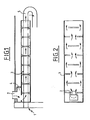
- la Fig. 1 est une vue schématique partielle en coupe longitudinale d'un réchauffeur classique;
- la Fig. 2 est une vue de dessus de la Fig. 1 représentant les chicanes;
- la Fig. 3 est une vue partielle en coupe transversale d'un réchauffeur selon l'invention; et
- la Fig. 4 est une vue en perspective du caisson de surchauffe présent dans le réchauffeur représenté sur la Fig. 3.
- Fig. 1 is a partial schematic view in longitudinal section of a conventional heater;
- Fig. 2 is a top view of FIG. 1 representing the baffles;
- Fig. 3 is a partial view in cross section of a heater according to the invention; and
- Fig. 4 is a perspective view of the overheating chamber present in the heater shown in FIG. 3.
Le réchauffeur (1) représente sur les Fig. 1 et 2 est un réchauffeur classique . A la partie supérieure du réchauffeur 1 est disposée une entrée 2 de vapeur surchauffée. Cette entrée est reliée à un caisson de désurchauffe 3 horizontal par l'intermédiaire d'un caisson de distribution 4. Le caisson est traversé longitudinalement par des tubes tels que 5. Des chicanes verticales sont disposées à l'intérieur du caisson 3. Ces chicanes servent en partie à supporter les tubes 5.The heater (1) represents in Figs. 1 and 2 is a conventional heater. At the upper part of the
Dans un tel caisson la vapeur subit une série de changements de direction qui contribuent à augmenter la perte de charge.In such a box the steam undergoes a series of changes of direction which contribute to increasing the pressure drop.
En outre l'entrée de la vapeur dans le caisson ainsi que sa sortie ont lieu dans des endroits très localisés entraînant des impacts néfastes par la vapeur.In addition, the entry of steam into the box as well as its exit take place in very localized locations causing harmful impacts by the steam.
Le réchauffeur 10 selon l'invention représenté sur la Fig. 3 comprend une enveloppe cylindrique 11.The heater 10 according to the invention shown in FIG. 3 comprises a
A la partie supérieure du réchauffeur 10 est disposée une entrée verticale 12 de vapeur surchauffée Cette entrée 12 est reliée à un caisson de désurchauffe 13 disposé horizontalement par l'intermédiaire d'un caisson de distribution 14 disposé horizontalement.At the upper part of the heater 10 is disposed a
Les caissons 13 et 14 ont des longueurs sensiblement égales entre elles et sont séparées par une paroi horizontale 15.The
Le caisson de distribution comprend en outre une paroi horizontale supérieure 16,une.paroi latérale verticale.17 et une paroi latérale 18 inclinée plane proche de la paroi de l'enveloppe 11 du réchauffeur et se raccordant à la paroi inférieure horizontale 19 du caisson 13 par l'intermédiaire d'une paroi verticale 20.The distribution box further comprises an upper horizontal wall 16, a
Un espace est ménagé entre la paroi de séparation 15 et la paroi inclinée 18 sur toutes leurs longueurs pour permettre l'entrée de la vapeur dans le caisson de désurchauffe 13 à partir du caisson de distribution 14.A space is provided between the
La vapeur est ainsi introduite dans le caisson 13 le long de la paroi inclinée 18,puis passe entre les parois horizontales 15 et 19 où est disposé un faisceau de tubes 21, horizontaux et parallèles à l'axe de l'enveloppe cylindrique 11.Steam is thus introduced into the
Ces tubes 21 sont supportés par une série de plaques 22 orthogonales aux tubes.Ces plaques sont d'un seul tenant et ont la forme d'un rectangle à coins supérieurs coupés. Ces plaques occupent la totalité de la section transversale du caisson 13 à l'exception d'une zone au voisinage des parois 18 et 20.These
Ces plaques servent non seulement à supporter les tubes 21,mais également à guider la vapeur qui circule ainsi en courants parallèles entre les plaques 22.These plates serve not only to support the
La vapeur sort du caisson 13 au voisinage de la paroi de l'enveloppe cylindrique 11 dans une zone où le réchauffeur est dépourvu de tubes de condensation,l'ensemble des tubes de condensation tels que 23 étant disposés à un niveau inférieur au niveau de la paroi inférieure 19 du caisson 13.The vapor leaves the
Il apparaît,aussi bien au niveau de l'entrée de la vapeur dans le caisson 13 de désurchauffe qu'au niveau de la sortie de la vapeur de ce caisson,qu'il n'y a pas de localisation du passage de la vapeur.Les problèmes liés à une telle localisation sont ainsi évitésIt appears, both at the level of the entry of steam into the
D'autre part,on évite également grâce à la présente invention les pertes de charge importantes que l'on avait dans la technique antérieure.On the other hand, it also avoids with the present invention the large pressure drops that were in the prior art.
Des descriptions du réchauffeur représentées sur les Fig.3 et 4 ne sont données qu'à titre d'exemple (avec une entrée de vapeur verticale et des tubes horizontaux). Toute autre orientation des réchauffeurs est possible.En particulier,l'entrée de vapeur peut être horizontale et les tubes verticaux.Descriptions of the heater shown in Figs. 3 and 4 are given by way of example only (with a vertical steam inlet and horizontal tubes). Any other orientation of the heaters is possible, in particular the steam inlet can be horizontal and the tubes vertical.
En outre,le caisson de distribution peut comporter à la place de la paroi inclinée 18 et de la paroi verticale 20,une paroi unique courbe se raccordant aux parois 16 et 19 et proche de la paroi de l'enveloppe 11.In addition, the distribution box can comprise, instead of the
Claims (6)
Priority Applications (5)
| Application Number | Priority Date | Filing Date | Title |
|---|---|---|---|
| AT83401463T ATE25284T1 (en) | 1983-07-13 | 1983-07-13 | FEED WATER PREHEATER WITH DESHEATER ESPECIALLY FOR THERMAL POWER PLANTS. |
| DE8383401463T DE3369553D1 (en) | 1983-07-13 | 1983-07-13 | Feed-water preheater with a desuperheater, in particular for a thermal power plant |
| EP83401463A EP0131670B2 (en) | 1983-07-13 | 1983-07-13 | Feed-water preheater with a desuperheater, in particular for a thermal power plant |
| AU27214/84A AU565700B2 (en) | 1983-07-13 | 1984-04-24 | Feed-water heater |
| ZA845385A ZA845385B (en) | 1983-07-13 | 1984-07-12 | Feed-water heater,in particular for a thermal electric power station including a de-superheating zone |
Applications Claiming Priority (1)
| Application Number | Priority Date | Filing Date | Title |
|---|---|---|---|
| EP83401463A EP0131670B2 (en) | 1983-07-13 | 1983-07-13 | Feed-water preheater with a desuperheater, in particular for a thermal power plant |
Publications (3)
| Publication Number | Publication Date |
|---|---|
| EP0131670A1 true EP0131670A1 (en) | 1985-01-23 |
| EP0131670B1 EP0131670B1 (en) | 1987-01-28 |
| EP0131670B2 EP0131670B2 (en) | 1991-01-02 |
Family
ID=8191422
Family Applications (1)
| Application Number | Title | Priority Date | Filing Date |
|---|---|---|---|
| EP83401463A Expired - Lifetime EP0131670B2 (en) | 1983-07-13 | 1983-07-13 | Feed-water preheater with a desuperheater, in particular for a thermal power plant |
Country Status (5)
| Country | Link |
|---|---|
| EP (1) | EP0131670B2 (en) |
| AT (1) | ATE25284T1 (en) |
| AU (1) | AU565700B2 (en) |
| DE (1) | DE3369553D1 (en) |
| ZA (1) | ZA845385B (en) |
Citations (4)
| Publication number | Priority date | Publication date | Assignee | Title |
|---|---|---|---|---|
| DE365685C (en) * | 1922-12-21 | Friedrich Werle | Feed water preheater for heating with exhaust steam | |
| GB273803A (en) * | 1926-04-07 | 1927-07-07 | British Thomson Houston Co Ltd | Improvements in and relating to feed water heating systems and apparatus therefor |
| GB931698A (en) * | 1960-09-22 | 1963-07-17 | Richardsons Westgarth & Co | Improvements in or relating to feed-water heaters |
| FR2427550A1 (en) * | 1978-05-31 | 1979-12-28 | Bbc Brown Boveri & Cie | SUPPLY WATER HEATER |
-
1983
- 1983-07-13 EP EP83401463A patent/EP0131670B2/en not_active Expired - Lifetime
- 1983-07-13 AT AT83401463T patent/ATE25284T1/en active
- 1983-07-13 DE DE8383401463T patent/DE3369553D1/en not_active Expired
-
1984
- 1984-04-24 AU AU27214/84A patent/AU565700B2/en not_active Ceased
- 1984-07-12 ZA ZA845385A patent/ZA845385B/en unknown
Patent Citations (4)
| Publication number | Priority date | Publication date | Assignee | Title |
|---|---|---|---|---|
| DE365685C (en) * | 1922-12-21 | Friedrich Werle | Feed water preheater for heating with exhaust steam | |
| GB273803A (en) * | 1926-04-07 | 1927-07-07 | British Thomson Houston Co Ltd | Improvements in and relating to feed water heating systems and apparatus therefor |
| GB931698A (en) * | 1960-09-22 | 1963-07-17 | Richardsons Westgarth & Co | Improvements in or relating to feed-water heaters |
| FR2427550A1 (en) * | 1978-05-31 | 1979-12-28 | Bbc Brown Boveri & Cie | SUPPLY WATER HEATER |
Also Published As
| Publication number | Publication date |
|---|---|
| AU565700B2 (en) | 1987-09-24 |
| DE3369553D1 (en) | 1987-03-05 |
| AU2721484A (en) | 1985-01-17 |
| ZA845385B (en) | 1985-02-27 |
| ATE25284T1 (en) | 1987-02-15 |
| EP0131670B2 (en) | 1991-01-02 |
| EP0131670B1 (en) | 1987-01-28 |
Similar Documents
| Publication | Publication Date | Title |
|---|---|---|
| RU2109209C1 (en) | Steam generator | |
| EP0131670B1 (en) | Feed-water preheater with a desuperheater, in particular for a thermal power plant | |
| FR2608263A1 (en) | HEAT EXCHANGER WITH ADJUSTABLE TRANSVERSAL FLOW OF THE HEATER, HAVING TWO HOT SURFACES | |
| FR2465979A1 (en) | CONDENSER WITH HEAT TRANSFER CHARACTERISTICS | |
| EP0141707B2 (en) | Condensing boiler for heating a heat carrier fluid | |
| CA1274734A (en) | Steam drying and superheating steam through heat exchange | |
| FR2499233A1 (en) | Heat exchanger using module of tubes and plates - esp. radiator or air conditioner for motor vehicles, where tubes are spaced closer together at centre of module to reduce mfg. costs | |
| EP0373027A1 (en) | Condensing boiler for heating with a heat-conveying liquid | |
| EP0058356B1 (en) | Element of a feed-water heater of a steam boiler and feed-water heater | |
| EP0898115B1 (en) | Boiler with external dense fluidised bed | |
| EP0568434B1 (en) | Distributing and partitioning device for feed and recirculation water in the secondary side of a steam generator | |
| EP0005225A1 (en) | Apparatus for extracting moisture from and for reheating steam | |
| RU2164322C2 (en) | Straight-flow stream generator with evaporation tubes arranged in a spiral | |
| CH625869A5 (en) | ||
| FR2524971A1 (en) | Small modular heat generator - has return water conduits in fume flue preheating water | |
| BE724037A (en) | ||
| BE486695A (en) | ||
| EP0051036B1 (en) | Surface heat exchanger for the recuperation of heat | |
| BE670138A (en) | ||
| BE387936A (en) | ||
| BE879140R (en) | VERTICAL STEAM SEPARATOR-SUPERHEATER | |
| BE569013A (en) | ||
| FR2542073A1 (en) | Solar energy collector panel | |
| FR2471571A1 (en) | Heat exchanger for cylindrical burner - has exterior finned vertical water tubes surrounding burner connected by headers | |
| FR2521269A1 (en) | Condensation boiler with liquid fuel burner - has circular tubular heat exchanger for water below combustion chamber |
Legal Events
| Date | Code | Title | Description |
|---|---|---|---|
| PUAI | Public reference made under article 153(3) epc to a published international application that has entered the european phase |
Free format text: ORIGINAL CODE: 0009012 |
|
| 17P | Request for examination filed |
Effective date: 19840705 |
|
| AK | Designated contracting states |
Designated state(s): AT BE CH DE FR GB IT LI LU NL SE |
|
| GRAA | (expected) grant |
Free format text: ORIGINAL CODE: 0009210 |
|
| AK | Designated contracting states |
Kind code of ref document: B1 Designated state(s): AT BE CH DE FR GB IT LI LU NL SE |
|
| REF | Corresponds to: |
Ref document number: 25284 Country of ref document: AT Date of ref document: 19870215 Kind code of ref document: T |
|
| ITF | It: translation for a ep patent filed | ||
| REF | Corresponds to: |
Ref document number: 3369553 Country of ref document: DE Date of ref document: 19870305 |
|
| PG25 | Lapsed in a contracting state [announced via postgrant information from national office to epo] |
Ref country code: LU Free format text: LAPSE BECAUSE OF NON-PAYMENT OF DUE FEES Effective date: 19870731 |
|
| PGFP | Annual fee paid to national office [announced via postgrant information from national office to epo] |
Ref country code: NL Payment date: 19870731 Year of fee payment: 5 |
|
| PLBI | Opposition filed |
Free format text: ORIGINAL CODE: 0009260 |
|
| 26 | Opposition filed |
Opponent name: BBC BROWN,BOVERI AG Effective date: 19871023 |
|
| NLR1 | Nl: opposition has been filed with the epo |
Opponent name: BBC BROWN, BOVERI AG |
|
| PG25 | Lapsed in a contracting state [announced via postgrant information from national office to epo] |
Ref country code: GB Effective date: 19880713 Ref country code: AT Effective date: 19880713 |
|
| PLAB | Opposition data, opponent's data or that of the opponent's representative modified |
Free format text: ORIGINAL CODE: 0009299OPPO |
|
| PG25 | Lapsed in a contracting state [announced via postgrant information from national office to epo] |
Ref country code: NL Effective date: 19890201 |
|
| R26 | Opposition filed (corrected) |
Opponent name: ASEA BROWN BOVERI AG Effective date: 19871023 |
|
| NLV4 | Nl: lapsed or anulled due to non-payment of the annual fee | ||
| GBPC | Gb: european patent ceased through non-payment of renewal fee | ||
| PG25 | Lapsed in a contracting state [announced via postgrant information from national office to epo] |
Ref country code: FR Free format text: LAPSE BECAUSE OF NON-PAYMENT OF DUE FEES Effective date: 19890331 |
|
| REG | Reference to a national code |
Ref country code: FR Ref legal event code: ST |
|
| PUAH | Patent maintained in amended form |
Free format text: ORIGINAL CODE: 0009272 |
|
| STAA | Information on the status of an ep patent application or granted ep patent |
Free format text: STATUS: PATENT MAINTAINED AS AMENDED |
|
| 27A | Patent maintained in amended form |
Effective date: 19910102 |
|
| AK | Designated contracting states |
Kind code of ref document: B2 Designated state(s): AT BE CH DE FR GB IT LI LU NL SE |
|
| PGFP | Annual fee paid to national office [announced via postgrant information from national office to epo] |
Ref country code: CH Payment date: 19920514 Year of fee payment: 10 |
|
| PGFP | Annual fee paid to national office [announced via postgrant information from national office to epo] |
Ref country code: DE Payment date: 19920602 Year of fee payment: 10 |
|
| PGFP | Annual fee paid to national office [announced via postgrant information from national office to epo] |
Ref country code: SE Payment date: 19920724 Year of fee payment: 10 |
|
| PGFP | Annual fee paid to national office [announced via postgrant information from national office to epo] |
Ref country code: BE Payment date: 19920812 Year of fee payment: 10 |
|
| PG25 | Lapsed in a contracting state [announced via postgrant information from national office to epo] |
Ref country code: SE Effective date: 19930714 |
|
| PG25 | Lapsed in a contracting state [announced via postgrant information from national office to epo] |
Ref country code: LI Effective date: 19930731 Ref country code: CH Effective date: 19930731 Ref country code: BE Effective date: 19930731 |
|
| BERE | Be: lapsed |
Owner name: HAMON-SOBELCO S.A. Effective date: 19930731 |
|
| REG | Reference to a national code |
Ref country code: CH Ref legal event code: PL |
|
| PG25 | Lapsed in a contracting state [announced via postgrant information from national office to epo] |
Ref country code: DE Effective date: 19940401 |
|
| EUG | Se: european patent has lapsed |
Ref document number: 83401463.1 Effective date: 19940210 |