EP0130211B1 - Non-return valve for pulsating burners - Google Patents
Non-return valve for pulsating burners Download PDFInfo
- Publication number
- EP0130211B1 EP0130211B1 EP84900417A EP84900417A EP0130211B1 EP 0130211 B1 EP0130211 B1 EP 0130211B1 EP 84900417 A EP84900417 A EP 84900417A EP 84900417 A EP84900417 A EP 84900417A EP 0130211 B1 EP0130211 B1 EP 0130211B1
- Authority
- EP
- European Patent Office
- Prior art keywords
- ring
- valve
- return valve
- edge
- circumference edge
- Prior art date
- Legal status (The legal status is an assumption and is not a legal conclusion. Google has not performed a legal analysis and makes no representation as to the accuracy of the status listed.)
- Expired
Links
- 229910000831 Steel Inorganic materials 0.000 claims abstract description 10
- 239000010959 steel Substances 0.000 claims abstract description 10
- 239000004033 plastic Substances 0.000 claims description 4
- 229920003023 plastic Polymers 0.000 claims description 4
- 239000000463 material Substances 0.000 claims description 3
- 230000000284 resting effect Effects 0.000 claims 1
- 238000002485 combustion reaction Methods 0.000 description 12
- 210000002105 tongue Anatomy 0.000 description 11
- 239000003570 air Substances 0.000 description 6
- 241000446313 Lamella Species 0.000 description 3
- 239000000446 fuel Substances 0.000 description 3
- 230000006698 induction Effects 0.000 description 3
- 230000001419 dependent effect Effects 0.000 description 2
- 238000010586 diagram Methods 0.000 description 2
- 239000013013 elastic material Substances 0.000 description 2
- XLYOFNOQVPJJNP-UHFFFAOYSA-N water Substances O XLYOFNOQVPJJNP-UHFFFAOYSA-N 0.000 description 2
- 239000012080 ambient air Substances 0.000 description 1
- 238000013459 approach Methods 0.000 description 1
- 230000003247 decreasing effect Effects 0.000 description 1
- 238000006073 displacement reaction Methods 0.000 description 1
- -1 for example Substances 0.000 description 1
- 230000005484 gravity Effects 0.000 description 1
- 238000010438 heat treatment Methods 0.000 description 1
- 230000000977 initiatory effect Effects 0.000 description 1
- 239000007788 liquid Substances 0.000 description 1
- 238000004519 manufacturing process Methods 0.000 description 1
- 238000000034 method Methods 0.000 description 1
Images

Classifications
-
- F—MECHANICAL ENGINEERING; LIGHTING; HEATING; WEAPONS; BLASTING
- F23—COMBUSTION APPARATUS; COMBUSTION PROCESSES
- F23C—METHODS OR APPARATUS FOR COMBUSTION USING FLUID FUEL OR SOLID FUEL SUSPENDED IN A CARRIER GAS OR AIR
- F23C15/00—Apparatus in which combustion takes place in pulses influenced by acoustic resonance in a gas mass
-
- F—MECHANICAL ENGINEERING; LIGHTING; HEATING; WEAPONS; BLASTING
- F16—ENGINEERING ELEMENTS AND UNITS; GENERAL MEASURES FOR PRODUCING AND MAINTAINING EFFECTIVE FUNCTIONING OF MACHINES OR INSTALLATIONS; THERMAL INSULATION IN GENERAL
- F16K—VALVES; TAPS; COCKS; ACTUATING-FLOATS; DEVICES FOR VENTING OR AERATING
- F16K15/00—Check valves
- F16K15/14—Check valves with flexible valve members
- F16K15/144—Check valves with flexible valve members the closure elements being fixed along all or a part of their periphery
-
- F—MECHANICAL ENGINEERING; LIGHTING; HEATING; WEAPONS; BLASTING
- F16—ENGINEERING ELEMENTS AND UNITS; GENERAL MEASURES FOR PRODUCING AND MAINTAINING EFFECTIVE FUNCTIONING OF MACHINES OR INSTALLATIONS; THERMAL INSULATION IN GENERAL
- F16K—VALVES; TAPS; COCKS; ACTUATING-FLOATS; DEVICES FOR VENTING OR AERATING
- F16K15/00—Check valves
- F16K15/14—Check valves with flexible valve members
- F16K15/141—Check valves with flexible valve members the closure elements not being fixed to the valve body
- F16K15/142—Check valves with flexible valve members the closure elements not being fixed to the valve body the closure elements being shaped as solids of revolution, e.g. toroidal or cylindrical rings
-
- Y—GENERAL TAGGING OF NEW TECHNOLOGICAL DEVELOPMENTS; GENERAL TAGGING OF CROSS-SECTIONAL TECHNOLOGIES SPANNING OVER SEVERAL SECTIONS OF THE IPC; TECHNICAL SUBJECTS COVERED BY FORMER USPC CROSS-REFERENCE ART COLLECTIONS [XRACs] AND DIGESTS
- Y10—TECHNICAL SUBJECTS COVERED BY FORMER USPC
- Y10T—TECHNICAL SUBJECTS COVERED BY FORMER US CLASSIFICATION
- Y10T137/00—Fluid handling
- Y10T137/7722—Line condition change responsive valves
- Y10T137/7837—Direct response valves [i.e., check valve type]
- Y10T137/7879—Resilient material valve
- Y10T137/7888—With valve member flexing about securement
Definitions
- the present invention relates to a non-return valve in the air inlet of a pulsating burner, which may be of the type described in the US ⁇ A ⁇ 3 267 986 (K. B. Olsson), US ⁇ A ⁇ 3 267 985 (J. A. Kitchen) and US ⁇ A ⁇ 2 701 950 (L. R. Huber et al).
- the combustion air is inducted to the combustion chamber via a non-return valve, fuel being mixed into the air after the non-return valve.
- the fuel may be liquid, gaseous or pulverulent.
- the non-return valve opens and closes under the action of the sub- and excess pressure phases obtained in conjunction with the pulsating combustion. Since these phases alternate with a frequency of 60 pulses per second or more, for example, it is a question of very rapid cycles and accordingly extremely short intervals, during which the non-return valve shall reach its open position, remain in its open position and then close.
- the non-return valve comprises a plurality of resilient steel leaves, fastened at one end to form flexible tongues.
- a disadvantage with these is that they afford a rapidly increasing resistance to opening from the closed position, resulting in that they must be set slightly open in the initial position. When they are kept in the closed position during operation, there is thus an initial force co-acting to initiate opening of the valve tongue when it is subjected to the sub-pressure phase. Since there are a plurality of such valve tongues, this results in certain difficulties in achieving the same setting of all the tongues. Furthermore, the valve tongues are not exactly the same with regard to their spring properties, resulting in that they can have different attitudes in the fully open position.
- the fully open position can furthermore change to a greater or less extent with time, due to fatigue occurring in the tongues.
- the resilient valve tongues thus involve certain difficulties in achieving desired precision in the opening and closing movements of the valve, and maintaining this precision for long operational periods.
- a further disadvantage is that the valve tongues cannot be opened as rapidly as desired at the beginning of the sub-pressure phase, since the opening movement is braked by the spring bias of the tongue after the tongue has passed said initial position where it is somewhat open.
- the US Patent 3 267 985 describes the use of lamellae which are situated loosely on a seating and may be lifted from it to a given end position determining the completely closed position of the valve.
- a condition with this type of valve is that the apparatus is mounted vertically so that the lamellae are acted on vertically by gravity.
- the lamellae are disposed loosely on an abutment plate with orifices, such that excess pressure gas can be led through these holes to a lamella when it is to be lifted into engagement with the seating above itfor closing its inlet opening.
- a plurality of such non-return valves of comparatively small size must be used to obtain the necessary rapidity in the opening and closing movements.
- Each lamella must be controlled by axial guide means at the edge of the lamella, resulting in varying friction against its guide means and a certain risk that the non-return valve will operate with relatively different degrees of frictional resistance. In turn, this involves the risk that some valves will open or close more rapidly than others, and in its turn this can lead to operational disturbances of a more or less serious nature. Further to this there is the situation that during the sub-pressure phase, induction air should be distributed as evenly as possible in order that the lamellae of all the valves will be actuated as uniformly as possible. This also applies during the excess pressure phase, when the excess pressure shall lift the lamellae to the closing position.
- valves are subjected to different sub-pressures or excess pressures, this may also result in operational disturbances.
- the loose lamellae are to a certain extent dependent on the apparatus retaining a constant vertical attitude, since the function of these valves is based on vertical reciprocating displacement of the lamellae.
- the apparatus is fitted in a ship, for example, there is the risk that the lamellae are effected by lateral forces striving to deflect them from their normal path of motion, which may in turn result in operational disturbances as well.
- the non-return valve As far as impulse burners are concerned, it is generally applicable that the non-return valve, or valves, must operate with the least possible resistance in order to open and close rapidly, a further desire being that these movements shall be as distinct as possible and that they shall accurately adapt themselves to the pulsating combustion cycle, thereby to achieve effective combustion. More rapid opening and closing also enables higher heating power. A still further desire is that the non-return valve will be simple and cheap to manufacture, and easy to fit or exchange if so required.
- the object of the present invention is to provide a non-return valve for a pulse burner which eliminates the disadvantages with the known non-return valves as far as possible.
- the invention is based on a non-return valve operating with a ring, known per se, which is thin and flat, and of elastic material such as steel or plastics.
- a ring is illustrated in the US Patent 3 830 253, for example.
- the flat ring is defJected about a geometric axis at right-angles to the central axis of the ring, so that in an open position the ring abuts against an abutment surface constituting a part of a cylindrical surface.
- the spring bias will accordingly begin to grow immediately, which acts to retard the opening movement in the same way as with a spring non-return valve tongue.
- the invention relates to a valve of the kind disclosed in the preamble to the following main claim.
- such a non-return valve has the distinguishing features apparent from the characterizing portion of the following main claim.
- the invention involves the use of a thin flat ring, known per se, of elastically flexible material, which, according to the invention, is fitted in a new and special way in order to utilize intrinsic properties of the ring.
- a ring of thin elastic material such as steel or plastics, for example, steel with a thickness in the range of 0.15 to 0.30 mm.
- the ring has an outside diameter of about 12 cm and an inner diameter of about 7 cm, the width of the ring thus being about 2.5 cm.
- the edge circumference of the ring thus has two distinct separate ranges of movement, namely a first range where the axial force is extremely small, in the order of magnitude of some water column mm acting on the surface of the ring, and a second range where the force is many times greater, and results in undesired permanent deformation of the ring.
- the ring In the first movement range, the ring will form a truncated cone having varying size.
- this cone approaches the intermediate position mentioned above, the sloping surface of the cone forms a very small angle to the base thereof, in the order of magnitude 3°.
- To deflect the ring to the intermediate position from the initial or flat position thereof thus requires practically no force, i.e. it is extremely easy to come to the intermediate position, which means that the material in the ring affords very little resistance.
- the invention is based on the concept that these properties can be utilized in an extremely advantageous way in a non-return valve for a pulsating burner, with its rapid alternations between sub- and excess pressure phases.
- the ring is placed in a flat condition above an inlet, preferably in a form of a plurality of induction openings, or an induction slit, with one side of the ring facing towards a duct to the combustion chamber, and its other side facing towards the inlet communicating with ambient air, suitably via a sub-pressure chamber.
- the edge or outer edge portion of the ring is practically completely prevented from moving axially by it being disposed with a very small play in a slot, or the like.
- the inner edge of the ring is free to move axially. In practice, the fact that the play is not too small can be established by it still being possible to turn the ring.
- one side of the ring will be subjected to excess and sub-pressure phases caused by the combustion in the combustion chamber, while its other side is acted on by a varying sub-pressure.
- the direction of force alternates in correspondance to the frequency of the pulsating burner.
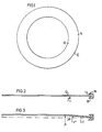
- Figure 1 is a plan view of a flat and thin steel ring
- Figure 2 illustrates the ring in a flat attitude supported on an annular support and held along its outer edge such that it may be rotated
- Figure 3 illustrates the ring upwardly deflected into the shape of a truncated cone, the height of which is very small in comparison with the diameter of its base
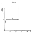
- Figure 4 is a diagram illustrating the force required to lift the inner edge of the ring as in Figure 3, as a function of the angle between the conical surface of the frustrum and its base.
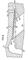
- Figure 5 is a schematic section through the inlet of a pulsating burner having a non-return valve in accordance with the invention
- Figure 6 is an enlarged view of Figure 5.
- the flat steel ring 10 illustrated in Figs. 1-3 suitably has a thickness in the range of 0.15 to 0.30 mm.
- the ring is supported on an annular support 11, and has its inner circumference edge free to move axially upwards in Fig. 2.
- the outer circumference edge 14 of the ring is practically completely axially fixed between a lower support 15 and an upper support 16, with a very small clearance, which however permits the ring to be rotated.
- the ring If the ring is now loaded with an axial, circumferential force, schematically illustrated by the arrow denoted by P, the ring will be deflected upwards into the shape of a truncated cone, the conical surface of which forms the angle V° with the base 17 thereof. Simultaneously with this upward deflection there is obtained a small radial movement inwards of the outer circumference edge of the ring, which is allowed by the minimum play between the supports 14 and 15. Initially, the force P is practically 0 and remains almost just as small until the angle V° reaches a value of about 3°. Passing this position can only occur if the force P is increased many times and to values which lead to permanent deformation of the ring.
- the graph according to Fig. 4 may be plotted. From the graph it will be seen that the force P in mm Vp increases from 0 to a value A not very far away from 0, namely only 2 mm Vp, and remains constant in this particular case up to 2.6° for the angle V° between the conical surface of the frustrum and its base. This force is thus so small that in practice it means that the ring does not offer any resistance in the range of movement ⁇ 2.6°. However, if it is attempted to exceed these limits, there will be immediate, totat retardation, since the required force increases practically vertically upwards in the diagram.
- This property of the ring with the described method of restraint at the outer circumference edge thereof in combination with the ring being thin, and thus having a very small mass, provides the properties of the ring desired in a non-return valve for the rapid pressure alternations occurring in a pulsating burner.
- Fig. 5 illustrates how a ring in accordance with the invention is fitted as a non-return valve in a schematically illustrated pulsating burner 18.
- a plurality of inlet openings 20 are made in an annular seating 19.
- the seating may be flat (horizontal in the figure) or somewhat sloping inwardly downwards.
- the thin steel ring 10, implemented as illustrated in Figs. 1-3, is placed on the seating.
- the ring is practically completely fixed in an axial direction along its outer circumfer - ence edge, between the outer edge portion of the seating 15A and the opposite edge portion 16A of a wall 21.
- the wall forms together with the seat an annular gap in which the ring is movable between its end positions.
- a small groove 19A is made at the outer edge of the seating 19, in order to give the outercircumfer- ence edge of the ring freedom of movement upwards and downwards when the ring is deflected upwards and downwards for opening and closing.
- the wall 21 In the vicinity of the inner edge portion of the ring the wall 21 is hollowed out at 22 to uncover this edge portion on its upper side 10A.
- the wall and seating merge thereafter in the walls to an axial duct 23 leading to the combustion chamber 24.
- Fuel is injected through a nozzle 25 and mixes with air before entering the combustion chamber.
- the air is inducted via a sub-pressure chamber 26.
- the invention is naturally not limited to the embodiment described hereinbefore. In certain cases it may be suitable to combine a plurality of non-return valves in accordance with the invention into a unit of co-axially arranged rings and seats, this resulting, inter alia, in the advantage that the non-return valve can have a smaller diameter, so that the unit takes up less room.
- the basic feature of the invention is to substantially prevent the outer edge of the ring to move axially and to obtain opening substantially by flexing the ring to the shape of a truncated cone.
- the opening of the valve is also dependent on the small axial movement allowable by said axial play.
- this will result in a decreasing efficiency which to a certain degree may be acceptable in orderto permitfor example a greater diameter of the pulse pipe, that is the outlet pipe from the combustion chamber.
Landscapes
- Engineering & Computer Science (AREA)
- General Engineering & Computer Science (AREA)
- Mechanical Engineering (AREA)
- Chemical & Material Sciences (AREA)
- Combustion & Propulsion (AREA)
- Fluidized-Bed Combustion And Resonant Combustion (AREA)
- Lift Valve (AREA)
- Feeding And Controlling Fuel (AREA)
- Multiple-Way Valves (AREA)
- Check Valves (AREA)
- Mechanically-Actuated Valves (AREA)
- Air Supply (AREA)
- Regulation And Control Of Combustion (AREA)
- Pressure-Spray And Ultrasonic-Wave- Spray Burners (AREA)
- Sliding Valves (AREA)
- Photosensitive Polymer And Photoresist Processing (AREA)
- Compositions Of Macromolecular Compounds (AREA)
- Lubricants (AREA)
Priority Applications (1)
| Application Number | Priority Date | Filing Date | Title |
|---|---|---|---|
| AT84900417T ATE27480T1 (de) | 1982-12-30 | 1983-12-30 | Ein-richtungsventil fuer pulsierende brenner. |
Applications Claiming Priority (2)
| Application Number | Priority Date | Filing Date | Title |
|---|---|---|---|
| SE8207522 | 1982-12-30 | ||
| SE8207522A SE435098B (sv) | 1982-12-30 | 1982-12-30 | Backventil i luftinloppet till en pulsbrennare |
Publications (2)
| Publication Number | Publication Date |
|---|---|
| EP0130211A1 EP0130211A1 (en) | 1985-01-09 |
| EP0130211B1 true EP0130211B1 (en) | 1987-05-27 |
Family
ID=20349220
Family Applications (1)
| Application Number | Title | Priority Date | Filing Date |
|---|---|---|---|
| EP84900417A Expired EP0130211B1 (en) | 1982-12-30 | 1983-12-30 | Non-return valve for pulsating burners |
Country Status (12)
| Country | Link |
|---|---|
| US (1) | US4906174A (enExample) |
| EP (1) | EP0130211B1 (enExample) |
| JP (1) | JPS60500307A (enExample) |
| AT (1) | ATE27480T1 (enExample) |
| AU (1) | AU571483B2 (enExample) |
| DE (1) | DE3371806D1 (enExample) |
| DK (1) | DK159292C (enExample) |
| FI (1) | FI75220C (enExample) |
| NO (1) | NO154443C (enExample) |
| SE (1) | SE435098B (enExample) |
| SU (1) | SU1327797A3 (enExample) |
| WO (1) | WO1984002762A1 (enExample) |
Families Citing this family (9)
| Publication number | Priority date | Publication date | Assignee | Title |
|---|---|---|---|---|
| FR2562212B1 (fr) * | 1984-03-29 | 1988-04-22 | Elf Aquitaine | Dispositif d'alimentation d'une chambre de combustion pulsatoire en carburant et en comburant |
| EP0227699B1 (de) * | 1985-06-12 | 1989-01-04 | PLETZER, Georg | Feuerungseinrichtung |
| FR2596853B1 (fr) * | 1986-04-04 | 1990-03-23 | Elf Aquitaine | Perfectionnements aux dispositifs d'alimentation d'une chambre de combustion pulsatoire d'un melange de comburant et de carburant |
| FR2596854B1 (fr) * | 1986-04-04 | 1990-01-26 | Elf Aquitaine | Vanne a clapet unique pour chaudiere a gaz |
| SE459986B (sv) * | 1987-04-09 | 1989-08-28 | Asea Stal Ab | Kraftanlaeggning med cyklonrenare med kylda cyklonben |
| SE464540B (sv) * | 1989-08-24 | 1991-05-06 | Pulsonex Ab | Pulsbraennare foer varmvattenpannor, vars hals kyls av ett utlopp foer varmvatten |
| US5277560A (en) * | 1991-06-26 | 1994-01-11 | Holset Engineering Company, Inc. | Ring valve type air compressor with deformable ring valves |
| US5213487A (en) * | 1991-06-26 | 1993-05-25 | Holset Engineering Company, Inc. | Ring valve type air compressor with deformable ring valves |
| FR2936299B1 (fr) * | 2008-09-25 | 2010-12-24 | Muller & Cie Soc | Chaudiere pulsatoire avec vanne a clapet |
Family Cites Families (15)
| Publication number | Priority date | Publication date | Assignee | Title |
|---|---|---|---|---|
| FR617642A (fr) * | 1925-06-20 | 1927-02-23 | Gasaccumulator Svenska Ab | Perfectionnements aux appareils à gaz pour feux à éclats |
| US2585863A (en) * | 1946-04-01 | 1952-02-12 | Maytag Co | Snap-action relief valve |
| US2701950A (en) * | 1952-07-26 | 1955-02-15 | Swingfire Bahamas Ltd | Combustion device and check valve therefor |
| US2950592A (en) * | 1954-01-06 | 1960-08-30 | Curtis Automotive Devices Inc | Resonant pulse jet engine having an engine valve antechamber |
| US2979901A (en) * | 1958-09-02 | 1961-04-18 | Curtis Automotive Devices Inc | Pulse jet engine |
| US3036592A (en) * | 1959-02-16 | 1962-05-29 | Garrett Corp | Valve assembly |
| SE197021C1 (enExample) * | 1960-09-22 | 1965-07-06 | ||
| FR1301164A (fr) * | 1961-09-19 | 1962-08-10 | Gustavsbergs Fabriker Ab | Foyer à combustion intermittente |
| GB1023752A (en) * | 1962-05-18 | 1966-03-23 | Karl Borje Olsson | Improvements in or relating to an oscillating gas column combustion apparatus |
| US3270771A (en) * | 1963-06-11 | 1966-09-06 | Robertshaw Controls Co | Resilient disc check valve |
| US3267985A (en) * | 1964-03-12 | 1966-08-23 | John A Kitchen | Pulse combustion apparatus |
| US3430648A (en) * | 1966-08-19 | 1969-03-04 | Fruehauf Corp | Vent check valve |
| GB1346169A (en) * | 1970-03-26 | 1974-02-06 | Girling Ltd | Fluid flow control valves |
| US3830253A (en) * | 1973-02-12 | 1974-08-20 | Trane Co | Compressor valve apparatus |
| US4248585A (en) * | 1978-12-04 | 1981-02-03 | Gulf Oil Corporation | Flare ignition apparatus |
-
1982
- 1982-12-30 SE SE8207522A patent/SE435098B/sv not_active IP Right Cessation
-
1983
- 1983-12-30 DE DE8484900417T patent/DE3371806D1/de not_active Expired
- 1983-12-30 WO PCT/SE1983/000488 patent/WO1984002762A1/en not_active Ceased
- 1983-12-30 AT AT84900417T patent/ATE27480T1/de not_active IP Right Cessation
- 1983-12-30 EP EP84900417A patent/EP0130211B1/en not_active Expired
- 1983-12-30 JP JP59500510A patent/JPS60500307A/ja active Granted
- 1983-12-30 AU AU24178/84A patent/AU571483B2/en not_active Ceased
-
1984
- 1984-08-20 NO NO84843319A patent/NO154443C/no unknown
- 1984-08-28 FI FI843389A patent/FI75220C/fi not_active IP Right Cessation
- 1984-08-28 DK DK409984A patent/DK159292C/da not_active IP Right Cessation
- 1984-08-29 SU SU843785906A patent/SU1327797A3/ru active
-
1989
- 1989-05-30 US US07/361,833 patent/US4906174A/en not_active Expired - Lifetime
Also Published As
| Publication number | Publication date |
|---|---|
| DK159292B (da) | 1990-09-24 |
| FI75220B (fi) | 1988-01-29 |
| SE435098B (sv) | 1984-09-03 |
| NO843319L (no) | 1984-08-20 |
| AU2417884A (en) | 1984-08-02 |
| JPH0518009B2 (enExample) | 1993-03-10 |
| FI75220C (fi) | 1988-05-09 |
| DK159292C (da) | 1991-02-25 |
| JPS60500307A (ja) | 1985-03-07 |
| NO154443C (no) | 1986-09-17 |
| SE8207522L (sv) | 1984-07-01 |
| ATE27480T1 (de) | 1987-06-15 |
| DK409984A (da) | 1984-08-28 |
| SU1327797A3 (ru) | 1987-07-30 |
| FI843389A0 (fi) | 1984-08-28 |
| DK409984D0 (da) | 1984-08-28 |
| WO1984002762A1 (en) | 1984-07-19 |
| DE3371806D1 (en) | 1987-07-02 |
| EP0130211A1 (en) | 1985-01-09 |
| AU571483B2 (en) | 1988-04-21 |
| US4906174A (en) | 1990-03-06 |
| NO154443B (no) | 1986-06-09 |
| SE8207522D0 (sv) | 1982-12-30 |
| FI843389A7 (fi) | 1984-08-28 |
Similar Documents
| Publication | Publication Date | Title |
|---|---|---|
| EP0130211B1 (en) | Non-return valve for pulsating burners | |
| US4148336A (en) | Pilot controlled membrane valve | |
| KR890005025B1 (ko) | 전자기 연료분사기의 오리피스 가름판 | |
| US5383646A (en) | Diaphragm control valve | |
| US5133334A (en) | Burner construction and method of making the same | |
| US5095950A (en) | Fluid mixing apparatus with progressive valve means | |
| CA1232821A (en) | Non-return valve for pulsating burners | |
| AU592442B2 (en) | Improved safety relief valve | |
| KR100323937B1 (ko) | 왕복내연기관의연료분사밸브 | |
| WO1999056061A1 (en) | Cyclic flow valve | |
| US1589245A (en) | Injection valve | |
| CN110657268A (zh) | 控制阀 | |
| US3557837A (en) | Modulating valve | |
| GB2189841A (en) | Injection nozzle for injecting fuel into the combustion chamber of an air-compressing fuel-injection engine | |
| JPH04248080A (ja) | 安全弁 | |
| IT8448054A1 (it) | Valvola di non ritorno per bruciatori pulsanti | |
| US2631605A (en) | Spring loaded safety valve | |
| JPS62163122A (ja) | 減圧弁 | |
| US5850848A (en) | Float valve | |
| US11788644B2 (en) | Proportional valve, electric shower incorporating the proportional valve and tap incorporating same | |
| US344866A (en) | George w | |
| US1107698A (en) | Carbureter. | |
| CN114658904A (zh) | 一种燃气稳压阀 | |
| JPH0418016Y2 (enExample) | ||
| JPH0449691Y2 (enExample) |
Legal Events
| Date | Code | Title | Description |
|---|---|---|---|
| PUAI | Public reference made under article 153(3) epc to a published international application that has entered the european phase |
Free format text: ORIGINAL CODE: 0009012 |
|
| AK | Designated contracting states |
Designated state(s): AT BE CH DE FR GB LI LU NL |
|
| 17P | Request for examination filed |
Effective date: 19841220 |
|
| GRAA | (expected) grant |
Free format text: ORIGINAL CODE: 0009210 |
|
| AK | Designated contracting states |
Kind code of ref document: B1 Designated state(s): AT BE CH DE FR GB LI LU NL |
|
| REF | Corresponds to: |
Ref document number: 27480 Country of ref document: AT Date of ref document: 19870615 Kind code of ref document: T |
|
| REF | Corresponds to: |
Ref document number: 3371806 Country of ref document: DE Date of ref document: 19870702 |
|
| ET | Fr: translation filed | ||
| PG25 | Lapsed in a contracting state [announced via postgrant information from national office to epo] |
Ref country code: LU Free format text: LAPSE BECAUSE OF NON-PAYMENT OF DUE FEES Effective date: 19871231 |
|
| PLBE | No opposition filed within time limit |
Free format text: ORIGINAL CODE: 0009261 |
|
| STAA | Information on the status of an ep patent application or granted ep patent |
Free format text: STATUS: NO OPPOSITION FILED WITHIN TIME LIMIT |
|
| 26N | No opposition filed | ||
| PGFP | Annual fee paid to national office [announced via postgrant information from national office to epo] |
Ref country code: LU Payment date: 19891229 Year of fee payment: 7 Ref country code: AT Payment date: 19891229 Year of fee payment: 7 |
|
| PGFP | Annual fee paid to national office [announced via postgrant information from national office to epo] |
Ref country code: BE Payment date: 19900112 Year of fee payment: 7 |
|
| PG25 | Lapsed in a contracting state [announced via postgrant information from national office to epo] |
Ref country code: AT Effective date: 19901230 |
|
| PG25 | Lapsed in a contracting state [announced via postgrant information from national office to epo] |
Ref country code: BE Effective date: 19901231 |
|
| BERE | Be: lapsed |
Owner name: MARECK B.V. Effective date: 19901231 |
|
| REG | Reference to a national code |
Ref country code: GB Ref legal event code: IF02 |
|
| PGFP | Annual fee paid to national office [announced via postgrant information from national office to epo] |
Ref country code: NL Payment date: 20021224 Year of fee payment: 20 Ref country code: GB Payment date: 20021224 Year of fee payment: 20 |
|
| PGFP | Annual fee paid to national office [announced via postgrant information from national office to epo] |
Ref country code: FR Payment date: 20021230 Year of fee payment: 20 Ref country code: CH Payment date: 20021230 Year of fee payment: 20 |
|
| PGFP | Annual fee paid to national office [announced via postgrant information from national office to epo] |
Ref country code: DE Payment date: 20030124 Year of fee payment: 20 |
|
| PG25 | Lapsed in a contracting state [announced via postgrant information from national office to epo] |
Ref country code: LI Free format text: LAPSE BECAUSE OF EXPIRATION OF PROTECTION Effective date: 20031229 Ref country code: GB Free format text: LAPSE BECAUSE OF EXPIRATION OF PROTECTION Effective date: 20031229 Ref country code: CH Free format text: LAPSE BECAUSE OF EXPIRATION OF PROTECTION Effective date: 20031229 |
|
| PG25 | Lapsed in a contracting state [announced via postgrant information from national office to epo] |
Ref country code: NL Free format text: LAPSE BECAUSE OF EXPIRATION OF PROTECTION Effective date: 20031230 |
|
| REG | Reference to a national code |
Ref country code: GB Ref legal event code: PE20 |
|
| REG | Reference to a national code |
Ref country code: CH Ref legal event code: PL |
|
| NLV7 | Nl: ceased due to reaching the maximum lifetime of a patent |
Effective date: 20031230 |