EP0129946A2 - Scheibenartige Transfervorrichtung für Behälter - Google Patents
Scheibenartige Transfervorrichtung für Behälter Download PDFInfo
- Publication number
- EP0129946A2 EP0129946A2 EP84300459A EP84300459A EP0129946A2 EP 0129946 A2 EP0129946 A2 EP 0129946A2 EP 84300459 A EP84300459 A EP 84300459A EP 84300459 A EP84300459 A EP 84300459A EP 0129946 A2 EP0129946 A2 EP 0129946A2
- Authority
- EP
- European Patent Office
- Prior art keywords
- container
- carrying apparatus
- vacuum
- continuously
- continuously moving
- Prior art date
- Legal status (The legal status is an assumption and is not a legal conclusion. Google has not performed a legal analysis and makes no representation as to the accuracy of the status listed.)
- Granted
Links
Images


Classifications
-
- B—PERFORMING OPERATIONS; TRANSPORTING
- B41—PRINTING; LINING MACHINES; TYPEWRITERS; STAMPS
- B41F—PRINTING MACHINES OR PRESSES
- B41F17/00—Printing apparatus or machines of special types or for particular purposes, not otherwise provided for
- B41F17/08—Printing apparatus or machines of special types or for particular purposes, not otherwise provided for for printing on filamentary or elongated articles, or on articles with cylindrical surfaces
- B41F17/14—Printing apparatus or machines of special types or for particular purposes, not otherwise provided for for printing on filamentary or elongated articles, or on articles with cylindrical surfaces on articles of finite length
Definitions
- the present invention generally relates to the container manufacturing art and, more particularly, container conveyor and transfer apparatus used in connection with the decoration or coating of containers such as can body members.
- can body member type containers are conventionally decorated or coated by continuously moving decorator apparatus, sometimes also referred to as printing or printer or coater apparatus, which has a continuously rotatable container carrying mandrel wheel with circumferential spaced container carrying mandrel devices for carrying undecorated containers along a first arcuate path of movement from a loading station to a transfer station, with circumjacent ink applying devices being associated with the container along the path of movement thereof to apply ink images onto the outer peripheral container surfaces.
- continuously moving decorator apparatus sometimes also referred to as printing or printer or coater apparatus
- the decorated containers are conventionally transferred from the rotatable mandrel wheel to circumferentially spaced support devices on a continuously rotatable container transfer wheel which carries the decorated containers away from the rotatable mandrel wheel along a second arcuate path.
- the decorated containers are then conventionally directly transferred from the rotatable transfer wheel to longitudinally spaced support pins on a continuously moving container conveyor chain, sometimes referred to as a deco chain, by which the decorated containers are carried to and through an ink curing and drying oven. Examples of prior art apparatus of this type are shown in the following U.S. Pat. Nos. Porterfield 3,016,163; Brigham, et al.
- the present invention solves the foregoing problems by use of a rotatable transfer wheel without any moving mechanical parts of the type heretofore employed for causing axial movement of suction cups to receive decorated cans from the mandrel wheel and associate the decorated cans with the deco chain.
- the present invention comprises a relatively narrow width lightweight rotatable support disk means.
- a plurality of suction cup means are fixedly mounted in circumferentially spaced relationship along the periphery of the support disk means for movement in a fixed circular path.
- Vacuum passage means provided in the support disk means, connect each suction cup means to new and improved vacuum manifold means mounted adjacent the inner periphery of the support disk means.
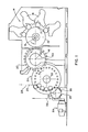
- the apparatus of the present invention is particularly adapted for use in a container decorating or coating system of the type illustrated in Figs. 1-3, which comprises: a conventional ink applicator means 14 including a blanket wheel means 15 rotatable about a horizontal axis of rotation 16 in engagement with plate cylinders 17 associated with ink application apparatus 18; a conventional continuously rotatable container carrying mandrel wheel means 22 for carrying containers to be decorated into engagement with the blanket wheel means 15 to coat or decorate the containers by application of ink images to the outer peripheral surface thereof; a conventional continuously rotatable decorated container transfer wheel means 24 for receiving decorated containers from the container mandrel wheel means 22 and for transferring the decorated containers to chain conveyor means 25 having spaced pin members 26 carried by a continuous inclined deco chain member 28; and motor means 29 for synchronously driving the aforedescribed apparatus by suitable connecting means (not shown).
- the rotatable mandrel wheel means 22 and the transfer wheel means 24 are ordinarily rotatable about vertically and horizontally spaced parallel horizontal axes 30, 32.
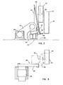
- the chain conveyor means 25 is driven by the motor means 29 through a transmission belt means 33, a speed reduction gear means 34, and a chain drive sprocket wheel 35, having an axis of rotation 36, mounted on a generally vertically upwardly inclined extending chain support frame assembly 37.
- the chain member 28, support frame assembly 37 and chain drive sprocket wheel 35 are inclined relative to a vertical plane 38, as has been conventional for many years as illustrated by Hartmeister U.S. Pat. No. 3,261,281 and D'Errico U.S. Pat. No.
- the container mandrel wheel means 22 which is rotatably movable along a rotational path in a vertical plane in the direction of the arrow, carries a plurality of circumferentially spaced container carrying mandrels 40 which extend horizontally parallel to the axis of rotation 30.
- the mandrel wheel means may be designed to carry decorated containers 41 from the ink application means 14 along an arcuate path or conventional cam means (not shown) may be provided to change the arcuate path of movement during a portion of the movement along a transfer zone opposite the transfer wheel means 24 for alignment with the arcuate path of movement of suction cup devices on the transfer wheel means.
- the present invention involves replacement of a conventional rotatable transfer wheel means 24 of a conventional decorator system with a rotatable disk transfer means 50 mounted between the conventional mandrel wheel means 22 and conventional chain conveyor means 25.
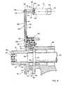
- the disk transfer means 50 comprises a one-piece annular support disk member 52, which is preferably made of machined aluminum plate or cast material to reduce weight, and has a relatively large diameter (e.g. 42.5 inches) and a relatively narrow width (e.g..625 inch).
- Disk member 52 has an inner annular rim portion 54 defining a central opening 56, an outer annular rim portion 58, and opposite flat parallel side surfaces 60, 62.
- a plurality of circumferentially spaced radially extending passages 64 are formed along side surface 60. Each passage 64 terminates in radially inner and outer transverse passages 66, 68 which extend through the opposite side surface 62 of support disk member 52.
- Support disk member 52 is fixedly attached to a hub means 70 by suitable bolt means 72.
- Hub means 70 comprises a flange member 74 fixed to a sleeve member 76 which is rotatably connected to an end portion 78 of a drive shaft 80 by bolt members 84 extending through an end cap member 86.
- Shaft 80 is rotatably supported in a hub member 88 by bearing means 90 on shaft portion 92.
- a spacer sleeve member 94 is mounted on shaft portion 96 between bearing means 90 and sleeve member 76 to provide a gap 98 between flange member 74 and the end surface 99 of hub member 88.
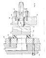
- An annular cover plate means 100 made of aluminum plate material is fixedly sealably mounted on disk surface 60 by suitable bolt means 102, 104, 106 to enclose radial passages 64 and transverse passages 66, 68.
- Each suction cup means 110 comprises an annular spacer member 112, having a central passage 114, a support head member 116 having a central passage 118, a resilient bumper pad member 120, and a resilient suction cup assembly 122 with a central passage 124.
- a vacuum supply means 130 sequentially connects and disconnects the suction cup means 110 relative to a source of vacuum (not shown) through passages 64, 66, 68, 114, 118, 124.
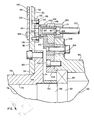
- Vacuum supply means 130 comprises an annular connecting plate means 132 having circumferentially spaced passages 134, Figs. 7 and 9, located opposite inner disk passages 66 and sealably fixedly mounted on disk side surface 62 by bolt means 135.
- Connecting plate 132 is preferably made of heat treated steel material with flat machined opposite parallel side surfaces 136, 138.
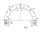
- Vacuum supply means 130 further comprises an arcuate manifold segment means 140 which is non-rotatably mounted opposite an 180° portion of wear plate 132. As shown on Figs.
- manifold means 140 comprises an 180 0 arcuate segment body member 142 made of machined steel material and a correspondingly shaped plastic wear member 144 bonded to outer side surface 146 of body member 142.
- Manifold means 140 has an arcuate slot 148, Fig. 10, which terminates at one end in a transverse annular vacuum supply passage 150 so as to provide vacuum throughout slot 148 and at the other end in a transverse wall portion 152 circumferentially spaced from a transverse annular passage 154. Additional vacuum supply passages and/or air passages may be provided as necessary or desirable.
- Manifold means 140 is circumferentially located and held against rotational movement by a plurality of annular sleeve members 160, 161, Figs. 5 and 10.
- Each sleeve member has an end portion with O-ring seals 162 located in axially slidably sealable relationship in manifold passages 150, 154 to enable relative axial displacement therebetween.
- An intermediate portion of each sleeve member with O-ring seals 164 is mounted in annular transverse passages 166, 167, Fig. 11, in an annular support ring means 168.
- a flange 169 at the rear end portion of each sleeve member abuts the side surface of support ring means 168 and is held thereon by mounting boxes 170, 171, Fig.
- the manifold means 140 is axially biased toward and held in engagement with rotatable connector plate 132 by a plurality of air operated piston devices 176, 177, 178, 179, 180, Figs. 7 and 8, slidably sealably mounted in annular passages 182, 183, 184, 185, 186, Fig. ll, in support ring means 168.
- Each piston device has an O-ring seal 188.
- Carrier ring means 168 is fixedly sealably mounted on carrier ring means 168 by suitable bolt means 196 mounted in bolt holes 198.
- a pipe nipple 200 is mounted in an air inlet port 194 and connected to a supply of presurrized air.
- Carrier ring means 168 is fixedly mounted on a flange portion 208 of hub portion 88 by bracket means 210 and bolt means 212 located radially outwardly of a bearing retainer ring means 214 fastened by bolt means 216.
- disk transfer means 50 is continuously rotated with shaft 80 in predetermined timed relationship to the continuously rotating mandrel wheel means and the continuously moving deco chain means.
- Vacuum connecting plate 132 rotates relative to the manifold means 140. Vacuum is maintained in arcuate slot 148.
- vacuum is applied to each associated section cup means l10 through passages 64, 66, 68 in disk support means 52 until each passage 134 rotates beyond the manifold means whereupon the vacuum is dissipated.
- Vacuum is applied to each of the suction cup means 110 when each suction cup means becomes aligned with a mandrel carrying a decorated can.
- the can on the mandrel is then transferred from the mandrel to the suction cup means by being blown off the mandrel and onto the aligned suction cup means by pressurized air.
- the can is held on.the suction cup means by vacuum until the can carried by the suction cup means becomes aligned with an associated pin on the deco chain means.
- vacuum is dissipated at the vacuum cup means.
- the inherent resiliency of the vacuum cap means causes outward flexing movement which axially displaces the can toward the pin while relasing the can from the vacuum cup means.
- both ends of groove 148 may be desirable to connect both ends of groove 148 to vacuum and provide a positive blowoff means in the form of an air port 210, Fig. 7, connected to a source of pressurized air. It is to be understood that the axial movement of the can caused by the inherent resiliency of the vacuum cup means is not required to transfer the can to the deco pin because the angle of inclination of the deco chain by itself may be sufficient to properly locate the deco pin in the can prior to release of vacuum. Also, positive can blow-off is not required.
- inventive concepts may also be used to accommodate various kinds and arrangements of container manufacturing apparatus including not only decorator system manufacturing apparatus including not only decorator system apparatus but also other kinds of manufacturing apparatus.
- container manufacturing apparatus including not only decorator system manufacturing apparatus including not only decorator system apparatus but also other kinds of manufacturing apparatus.
Landscapes
- Specific Conveyance Elements (AREA)
- Memory System Of A Hierarchy Structure (AREA)
- Coating Apparatus (AREA)
- Control Of Conveyors (AREA)
Priority Applications (1)
| Application Number | Priority Date | Filing Date | Title |
|---|---|---|---|
| AT84300459T ATE36671T1 (de) | 1983-02-07 | 1984-01-25 | Scheibenartige transfervorrichtung fuer behaelter. |
Applications Claiming Priority (2)
| Application Number | Priority Date | Filing Date | Title |
|---|---|---|---|
| US464555 | 1983-02-07 | ||
| US06/464,555 US4445431A (en) | 1983-02-07 | 1983-02-07 | Disk transfer system |
Publications (3)
| Publication Number | Publication Date |
|---|---|
| EP0129946A2 true EP0129946A2 (de) | 1985-01-02 |
| EP0129946A3 EP0129946A3 (en) | 1985-09-25 |
| EP0129946B1 EP0129946B1 (de) | 1988-08-24 |
Family
ID=23844397
Family Applications (1)
| Application Number | Title | Priority Date | Filing Date |
|---|---|---|---|
| EP84300459A Expired EP0129946B1 (de) | 1983-02-07 | 1984-01-25 | Scheibenartige Transfervorrichtung für Behälter |
Country Status (9)
| Country | Link |
|---|---|
| US (1) | US4445431A (de) |
| EP (1) | EP0129946B1 (de) |
| JP (1) | JPH0639157B2 (de) |
| AT (1) | ATE36671T1 (de) |
| AU (2) | AU563086B2 (de) |
| CA (1) | CA1201993A (de) |
| DE (1) | DE3473580D1 (de) |
| NZ (1) | NZ206935A (de) |
| ZA (1) | ZA84546B (de) |
Families Citing this family (11)
| Publication number | Priority date | Publication date | Assignee | Title |
|---|---|---|---|---|
| JPS62172040U (de) * | 1986-04-22 | 1987-10-31 | ||
| US4722432A (en) * | 1986-07-23 | 1988-02-02 | Doboy Packaging Machinery, Inc. | Rotary transfer apparatus |
| GB2200883B (en) * | 1987-02-11 | 1990-12-05 | Gersan Ets | Feeder |
| US4771879A (en) * | 1987-07-01 | 1988-09-20 | Adolph Coors Company | Container transfer system |
| US5148742A (en) * | 1991-01-10 | 1992-09-22 | Belgium Tool And Die Company | Can coater with improved deactivator responsive to absence of a workpiece |
| US5253580A (en) * | 1992-08-24 | 1993-10-19 | Dee Richard D | Apparatus for conveying a printed object |
| US5749631A (en) * | 1996-04-30 | 1998-05-12 | Sequa Corporation | Dual can rotating transfer plate to conveyor belt |
| CN1170749C (zh) | 1999-05-07 | 2004-10-13 | 赛夸公司 | 罐传送旋转盘系统 |
| US20170232776A1 (en) | 2014-10-01 | 2017-08-17 | E.I. Du Pont De Nemours And Company | Non-thermoplastic polyimide spindle cover |
| US11897710B2 (en) * | 2018-03-14 | 2024-02-13 | Stolle Machinery Company, Llc | Decorator assembly |
| BR112020018499A2 (pt) * | 2018-03-14 | 2020-12-29 | Stolle Machinery Company, Llc | Conjunto de decorador |
Citations (4)
| Publication number | Priority date | Publication date | Assignee | Title |
|---|---|---|---|---|
| US3019725A (en) * | 1960-03-14 | 1962-02-06 | Plax Corp | Supporting containers for printing thereon |
| US3339698A (en) * | 1966-02-04 | 1967-09-05 | Coors Porcelain Co | Can unloading and transferring machine |
| US3591047A (en) * | 1968-10-08 | 1971-07-06 | Continental Can Co | Cup bounce suppression by a vacuum |
| FR2416855A1 (fr) * | 1978-02-08 | 1979-09-07 | Schmalbach Lubeca | Dispositif pour retirer des boites ouvertes a une extremite, fraichement imprimees ou fraichement vernies, d'une roue a mandrins rotative |
Family Cites Families (6)
| Publication number | Priority date | Publication date | Assignee | Title |
|---|---|---|---|---|
| US3227070A (en) * | 1964-09-04 | 1966-01-04 | Ward E Brigham | High speed can printing press |
| US3250213A (en) * | 1964-12-16 | 1966-05-10 | Sun Chemical Corp | High speed tube decorating machines |
| US3766851A (en) * | 1971-11-15 | 1973-10-23 | Sun Chemical Corp | Continuous can printer and handling apparatus |
| US4048917A (en) * | 1975-09-26 | 1977-09-20 | Sun Chemical Corporation | Continuous motion printing apparatus |
| JPS5492810A (en) * | 1977-12-28 | 1979-07-23 | Coors Container Co | Continuous can printing and conveying method and apparatus |
| US4222479A (en) * | 1978-11-13 | 1980-09-16 | Coors Container Company | Container conveying and transfer system |
-
1983
- 1983-02-07 US US06/464,555 patent/US4445431A/en not_active Expired - Lifetime
-
1984
- 1984-01-20 CA CA000445769A patent/CA1201993A/en not_active Expired
- 1984-01-24 ZA ZA84546A patent/ZA84546B/xx unknown
- 1984-01-25 AT AT84300459T patent/ATE36671T1/de not_active IP Right Cessation
- 1984-01-25 EP EP84300459A patent/EP0129946B1/de not_active Expired
- 1984-01-25 AU AU23788/84A patent/AU563086B2/en not_active Ceased
- 1984-01-25 NZ NZ206935A patent/NZ206935A/en unknown
- 1984-01-25 DE DE8484300459T patent/DE3473580D1/de not_active Expired
- 1984-02-07 JP JP59020665A patent/JPH0639157B2/ja not_active Expired - Lifetime
-
1987
- 1987-04-28 AU AU72175/87A patent/AU575746B2/en not_active Ceased
Patent Citations (4)
| Publication number | Priority date | Publication date | Assignee | Title |
|---|---|---|---|---|
| US3019725A (en) * | 1960-03-14 | 1962-02-06 | Plax Corp | Supporting containers for printing thereon |
| US3339698A (en) * | 1966-02-04 | 1967-09-05 | Coors Porcelain Co | Can unloading and transferring machine |
| US3591047A (en) * | 1968-10-08 | 1971-07-06 | Continental Can Co | Cup bounce suppression by a vacuum |
| FR2416855A1 (fr) * | 1978-02-08 | 1979-09-07 | Schmalbach Lubeca | Dispositif pour retirer des boites ouvertes a une extremite, fraichement imprimees ou fraichement vernies, d'une roue a mandrins rotative |
Also Published As
| Publication number | Publication date |
|---|---|
| JPS59207245A (ja) | 1984-11-24 |
| US4445431A (en) | 1984-05-01 |
| AU575746B2 (en) | 1988-08-04 |
| AU563086B2 (en) | 1987-06-25 |
| ATE36671T1 (de) | 1988-09-15 |
| NZ206935A (en) | 1987-03-06 |
| ZA84546B (en) | 1984-11-28 |
| AU2378884A (en) | 1984-08-16 |
| AU7217587A (en) | 1987-08-20 |
| DE3473580D1 (en) | 1988-09-29 |
| CA1201993A (en) | 1986-03-18 |
| EP0129946B1 (de) | 1988-08-24 |
| EP0129946A3 (en) | 1985-09-25 |
| JPH0639157B2 (ja) | 1994-05-25 |
Similar Documents
| Publication | Publication Date | Title |
|---|---|---|
| US4509555A (en) | Disk transfer system | |
| US4445431A (en) | Disk transfer system | |
| CA2370395C (en) | Can transfer rotating plate system | |
| US6167805B1 (en) | Mandrel carrier for high speed can decorators | |
| US4771879A (en) | Container transfer system | |
| JPH0672816U (ja) | 漸次的にポートが設けられているラベル貼付機械用真空ドラム | |
| US5233922A (en) | Ink fountain for a can coater | |
| EP1011971B1 (de) | Drehtisch mit spindeln für eine einrichtung zum dekorieren von behältern | |
| US5148742A (en) | Can coater with improved deactivator responsive to absence of a workpiece | |
| RU2159206C2 (ru) | Устройство для переноса контейнеров | |
| US4974716A (en) | Device for feeding can barrels | |
| US4942955A (en) | Container transfer system | |
| NZ217449A (en) | Connecting ports on rotating disc to air or vacuum chamber in stationary manifold | |
| JPH07502476A (ja) | 弁手段を自動位置決めする装置と方法 | |
| EP0830250B1 (de) | Schieberventileinrichtung für eine dosendekorationsvorrichtung mit kontinuierlicher bewegung | |
| CA1205037A (en) | Disk transfer system | |
| MXPA98001618A (en) | Vertical track for mandrel unit of container movement cans |
Legal Events
| Date | Code | Title | Description |
|---|---|---|---|
| PUAI | Public reference made under article 153(3) epc to a published international application that has entered the european phase |
Free format text: ORIGINAL CODE: 0009012 |
|
| AK | Designated contracting states |
Designated state(s): AT BE CH DE FR GB IT LI NL SE |
|
| PUAL | Search report despatched |
Free format text: ORIGINAL CODE: 0009013 |
|
| AK | Designated contracting states |
Designated state(s): AT BE CH DE FR GB IT LI NL SE |
|
| 17P | Request for examination filed |
Effective date: 19860219 |
|
| 17Q | First examination report despatched |
Effective date: 19870219 |
|
| ITF | It: translation for a ep patent filed |
Owner name: BARZANO' E ZANARDO ROMA S.P.A. |
|
| GRAA | (expected) grant |
Free format text: ORIGINAL CODE: 0009210 |
|
| AK | Designated contracting states |
Kind code of ref document: B1 Designated state(s): AT BE CH DE FR GB IT LI NL SE |
|
| PG25 | Lapsed in a contracting state [announced via postgrant information from national office to epo] |
Ref country code: LI Effective date: 19880824 Ref country code: CH Effective date: 19880824 Ref country code: AT Effective date: 19880824 |
|
| REF | Corresponds to: |
Ref document number: 36671 Country of ref document: AT Date of ref document: 19880915 Kind code of ref document: T |
|
| REF | Corresponds to: |
Ref document number: 3473580 Country of ref document: DE Date of ref document: 19880929 |
|
| ET | Fr: translation filed | ||
| REG | Reference to a national code |
Ref country code: CH Ref legal event code: PL |
|
| PGFP | Annual fee paid to national office [announced via postgrant information from national office to epo] |
Ref country code: SE Payment date: 19890131 Year of fee payment: 6 Ref country code: NL Payment date: 19890131 Year of fee payment: 6 |
|
| PLBE | No opposition filed within time limit |
Free format text: ORIGINAL CODE: 0009261 |
|
| STAA | Information on the status of an ep patent application or granted ep patent |
Free format text: STATUS: NO OPPOSITION FILED WITHIN TIME LIMIT |
|
| 26N | No opposition filed | ||
| PG25 | Lapsed in a contracting state [announced via postgrant information from national office to epo] |
Ref country code: SE Effective date: 19900126 |
|
| PG25 | Lapsed in a contracting state [announced via postgrant information from national office to epo] |
Ref country code: NL Effective date: 19900801 |
|
| NLV4 | Nl: lapsed or anulled due to non-payment of the annual fee | ||
| PGFP | Annual fee paid to national office [announced via postgrant information from national office to epo] |
Ref country code: BE Payment date: 19911223 Year of fee payment: 9 |
|
| ITPR | It: changes in ownership of a european patent |
Owner name: CESSIONE;COORS BREWING COMPANY |
|
| REG | Reference to a national code |
Ref country code: GB Ref legal event code: 732 |
|
| ITTA | It: last paid annual fee | ||
| PG25 | Lapsed in a contracting state [announced via postgrant information from national office to epo] |
Ref country code: BE Effective date: 19930131 |
|
| BERE | Be: lapsed |
Owner name: COORS BREWING CY Effective date: 19930131 |
|
| REG | Reference to a national code |
Ref country code: FR Ref legal event code: TP |
|
| EUG | Se: european patent has lapsed |
Ref document number: 84300459.9 Effective date: 19901107 |
|
| PGFP | Annual fee paid to national office [announced via postgrant information from national office to epo] |
Ref country code: FR Payment date: 20010102 Year of fee payment: 18 |
|
| PGFP | Annual fee paid to national office [announced via postgrant information from national office to epo] |
Ref country code: DE Payment date: 20010103 Year of fee payment: 18 |
|
| PGFP | Annual fee paid to national office [announced via postgrant information from national office to epo] |
Ref country code: GB Payment date: 20010105 Year of fee payment: 18 |
|
| REG | Reference to a national code |
Ref country code: GB Ref legal event code: IF02 |
|
| PG25 | Lapsed in a contracting state [announced via postgrant information from national office to epo] |
Ref country code: GB Free format text: LAPSE BECAUSE OF NON-PAYMENT OF DUE FEES Effective date: 20020125 |
|
| PG25 | Lapsed in a contracting state [announced via postgrant information from national office to epo] |
Ref country code: DE Free format text: LAPSE BECAUSE OF NON-PAYMENT OF DUE FEES Effective date: 20020801 |
|
| GBPC | Gb: european patent ceased through non-payment of renewal fee |
Effective date: 20020125 |
|
| PG25 | Lapsed in a contracting state [announced via postgrant information from national office to epo] |
Ref country code: FR Free format text: LAPSE BECAUSE OF NON-PAYMENT OF DUE FEES Effective date: 20020930 |
|
| REG | Reference to a national code |
Ref country code: FR Ref legal event code: ST |