EP0129523B1 - An electrode chamber unit intended for an electrochemical cell having a porous percolation electrode - Google Patents
An electrode chamber unit intended for an electrochemical cell having a porous percolation electrode Download PDFInfo
- Publication number
- EP0129523B1 EP0129523B1 EP84850183A EP84850183A EP0129523B1 EP 0129523 B1 EP0129523 B1 EP 0129523B1 EP 84850183 A EP84850183 A EP 84850183A EP 84850183 A EP84850183 A EP 84850183A EP 0129523 B1 EP0129523 B1 EP 0129523B1
- Authority
- EP
- European Patent Office
- Prior art keywords
- frame
- electrode chamber
- central opening
- chamber unit
- electrode
- Prior art date
- Legal status (The legal status is an assumption and is not a legal conclusion. Google has not performed a legal analysis and makes no representation as to the accuracy of the status listed.)
- Expired
Links
Images

Classifications
-
- C—CHEMISTRY; METALLURGY
- C25—ELECTROLYTIC OR ELECTROPHORETIC PROCESSES; APPARATUS THEREFOR
- C25C—PROCESSES FOR THE ELECTROLYTIC PRODUCTION, RECOVERY OR REFINING OF METALS; APPARATUS THEREFOR
- C25C7/00—Constructional parts, or assemblies thereof, of cells; Servicing or operating of cells
-
- C—CHEMISTRY; METALLURGY
- C02—TREATMENT OF WATER, WASTE WATER, SEWAGE, OR SLUDGE
- C02F—TREATMENT OF WATER, WASTE WATER, SEWAGE, OR SLUDGE
- C02F1/00—Treatment of water, waste water, or sewage
- C02F1/46—Treatment of water, waste water, or sewage by electrochemical methods
- C02F1/461—Treatment of water, waste water, or sewage by electrochemical methods by electrolysis
- C02F1/46104—Devices therefor; Their operating or servicing
- C02F1/46109—Electrodes
- C02F1/46114—Electrodes in particulate form or with conductive and/or non conductive particles between them
-
- C—CHEMISTRY; METALLURGY
- C25—ELECTROLYTIC OR ELECTROPHORETIC PROCESSES; APPARATUS THEREFOR
- C25B—ELECTROLYTIC OR ELECTROPHORETIC PROCESSES FOR THE PRODUCTION OF COMPOUNDS OR NON-METALS; APPARATUS THEREFOR
- C25B11/00—Electrodes; Manufacture thereof not otherwise provided for
- C25B11/02—Electrodes; Manufacture thereof not otherwise provided for characterised by shape or form
- C25B11/037—Electrodes made of particles
-
- C—CHEMISTRY; METALLURGY
- C25—ELECTROLYTIC OR ELECTROPHORETIC PROCESSES; APPARATUS THEREFOR
- C25B—ELECTROLYTIC OR ELECTROPHORETIC PROCESSES FOR THE PRODUCTION OF COMPOUNDS OR NON-METALS; APPARATUS THEREFOR
- C25B9/00—Cells or assemblies of cells; Constructional parts of cells; Assemblies of constructional parts, e.g. electrode-diaphragm assemblies; Process-related cell features
- C25B9/40—Cells or assemblies of cells comprising electrodes made of particles; Assemblies of constructional parts thereof
- C25B9/47—Cells or assemblies of cells comprising electrodes made of particles; Assemblies of constructional parts thereof comprising static bed electrodes
-
- C—CHEMISTRY; METALLURGY
- C25—ELECTROLYTIC OR ELECTROPHORETIC PROCESSES; APPARATUS THEREFOR
- C25B—ELECTROLYTIC OR ELECTROPHORETIC PROCESSES FOR THE PRODUCTION OF COMPOUNDS OR NON-METALS; APPARATUS THEREFOR
- C25B9/00—Cells or assemblies of cells; Constructional parts of cells; Assemblies of constructional parts, e.g. electrode-diaphragm assemblies; Process-related cell features
- C25B9/70—Assemblies comprising two or more cells
-
- C—CHEMISTRY; METALLURGY
- C25—ELECTROLYTIC OR ELECTROPHORETIC PROCESSES; APPARATUS THEREFOR
- C25B—ELECTROLYTIC OR ELECTROPHORETIC PROCESSES FOR THE PRODUCTION OF COMPOUNDS OR NON-METALS; APPARATUS THEREFOR
- C25B9/00—Cells or assemblies of cells; Constructional parts of cells; Assemblies of constructional parts, e.g. electrode-diaphragm assemblies; Process-related cell features
- C25B9/70—Assemblies comprising two or more cells
- C25B9/73—Assemblies comprising two or more cells of the filter-press type
-
- C—CHEMISTRY; METALLURGY
- C25—ELECTROLYTIC OR ELECTROPHORETIC PROCESSES; APPARATUS THEREFOR
- C25B—ELECTROLYTIC OR ELECTROPHORETIC PROCESSES FOR THE PRODUCTION OF COMPOUNDS OR NON-METALS; APPARATUS THEREFOR
- C25B9/00—Cells or assemblies of cells; Constructional parts of cells; Assemblies of constructional parts, e.g. electrode-diaphragm assemblies; Process-related cell features
- C25B9/70—Assemblies comprising two or more cells
- C25B9/73—Assemblies comprising two or more cells of the filter-press type
- C25B9/75—Assemblies comprising two or more cells of the filter-press type having bipolar electrodes
Definitions
- the present invention relates to the field of electrochemical cells, particularly electrolytic cells, which contain at least one porous percolation electrode in the form of a bed of electrically conductive particles. More specifically the invention relates to a structure of an electrode in the form of a bed of conductive grains, or rather to a complete electrode chamber unit which can very easily be assembled into an electrochemical cell of the filter press configuration.
- the invention relates to the field of electrode chamber units in the form of beds of conductive grains, and it is simple to construct electrochemical cells with the desired number of units, with the desired thickness of the respective electrodes, with counter electrodes with the same structure as the electrode chamber units or counter electrodes of another type, e.g. solid plates etc., which in turn enables a simple disassembling of the cell, exchange or regeneration of individual electrodes, adjustment of cell structure and size to the intended field of use etc.
- the invention further relates to an electrochemical cell including the above-mentioned electrode chamber units and to a method of producing such an electrochemical cell.
- the ideal method of purifying wastewaters containing heavy metals would be a precipitation of the metals in a pure form with simultaneous desalination of the water to a purity allowing recycling in the process.
- the present invention enables an electrolytic metal precipitation which gives these advantages. Electrolytic metal precipitation from diluted solutions has previously not come into industrial use, due to the fact that conventional electrolysis with planar electrodes requires too large electrode areas to give a satisfactory purification effect, with the low final contents which are required these days (approximately 1 ppm). Under these conditions the electrolysis process is controlled by the transport of metal ions to the electrode surface (the cathode). To achieve a high material transport rate per volumetric unit, and thereby a small reactor volume, the cathode can instead be formed in accordance with the invention as a percolated porous body or a stable particulate bed with a high specific area.
- Cell structures of the filter press type are indeed also known, reference e.g. being made to US 4,274,939 and to DE-A-2948579, but in these cases the electrodes are of completely different structures, viz. in the form of solid plates or hanging carbon fibers respectively, which structures cannot possibly be compared with the beds of conductive grains which have so far been used within the field of porous percolation electrodes.
- Other examples of frames with solid electrodes are those disclosed in DE 3,221,371 A1 and SU 619 551.
- This document in one embodiment sets forth a method and device wherein packed bed technology is combined with a thin sheet filter press arrangement.
- the present invention has been found particularly usable in conjunction with the purification of wastewaters, e.g. washing water from the galvanizing industry, or mine water, but the new electrode chamber units and cells are by no means limited to just this use, but one of the great advantages of the invention is just that electrochemical cells can be tailored for practically any kind of electrochemical reaction of the electrolysis type.
- the current conductors of the electrode chamber units according to the invention can be implemented in different ways, most important, however, being that they do not disturb the electrolyte flow through the bed to any appreciable extent.
- the electrode chamber unit in accordance with the invention includes at least one substantially flat frame having a thickness within the range of 0.2-5 cm and defining a central opening that is filled with the electrically conductive grains so that these form a flat porous bed within said opening, the grains being kept in place within the central opening of the frame by sufficiently dense separators, which are arranged to cover the central opening on either side of the frame to form an electrode chamber, the frame being provided with at least one hole for supply and at least one hole for discharge of electrolyte, where said holes are in communication via inlet and outlet channels respectively with the central opening of the frame, and the frame including current conductors for the supply of electric current to the conductive particles via said frame, said current conductors comprising an electrode element located within said bed which element is a substantially flat tongue arranged with a space to the edge of the central opening or a metal net the dimensions of which are similar to or smaller than the dimensions of the central opening, and conducting means inserted through the peripheral edge of the frame.
- At least one frame it is to be understood in the present case that an alternative to a thick frame is two or more thinner frames, which make it possible to work with one and the same frame thickness but still vary the thickness of the electrode.
- the frames are placed against each other and can be regarded in relation to the remaining components of the electrode chamber unit as a single cohesive frame, the term "frame” being used for the sake of simplicity even in the cases where two or more frames are used in one and the same electrode.
- both the frame and the separators are preferably made in a polymeric material, thus enabling the achievement of the above-mentioned advantages, particularly if this polymeric material is a thermoplastic, injection mouldable material.
- the material for the frame and the separators respectively does not necessarily need to be the same polymeric material.
- polyethylene and polypropylene can be mentioned as examples of suitable materials for the frame
- the separator if made from another material than the frame, can be moulded e.g. from polyamide or polyester.
- these diaphragms can also function as separators.
- the diaphragm has a double function. Separate diaphragms can be used of course, which is illustrated more closely below.
- an electrochemical cell made up from the electrode chamber units will function in a way where the electric current and electrolyte flow are directed in a cross-flow pattern in relation to each other, which has been found to give considerably better performance than in those cases where the electric current and electrolyte flow are directed in a concurrent or countercurrent flow in relation to each other.
- the central opening of the frame, and thereby the electrode bed can be given different configurations, but it has been found that particularly favourable flow conditions and performances are achieved if the central opening has a substantially rectangular shape.
- the ratio longside:shortside of the rectangle is suitably at least 2:1 and preferably at least 4:1, a particularly favourable range being 4:1-10:1.
- the channels for supply and discharge of electrolyte to and from the central opening open out in the respective shortside of the rectangle, i.e. at opposing shortsides, advantageous conditions for the electrolysis are achieved.
- the thickness of the electrode frame, and thereby of the electrode should be kept comparatively small compared with the length and width, respectively, of the frame.
- the frame In absolute numbers this more specifically means that the frame generally has a thickness within the range of 0.2-5 cm, more preferably 0.5-2 cm and most preferably 0.5-1 cm.
- the requirements of the particulate electrode are the following: a good electrical conductor, chemically inert, usable both as a cathode and an anode and cheapness.
- the material which presently has shown to meet these demands in the best way is graphite, which is thus the preferred material for the conductive particles, but the invention is of course not limited to the use of this material only, since the idea is applicable to all other materials with similar properties.
- the size of the electrically conductive particles is easily determined by one skilled in the art for each individual case, depending on the particular conditions applying to the application in question. In general, however, the risk of channel formations and the requirement of reasonable pressure drops contradict too small particles or grains in the bed. A balance must be struck with the requirement of high specific area, which grows inversely proportional to the particle size.
- a usable range for particle size is, however, 0.5-5 mm, preferably 1-2 mm.
- the best purification conditions have been found to occur when the particles have an irregular shape, this being often preferable to a homogeneous spherical shape.
- the frame should preferably be surrounded on either side by a separate gasket, which is suitably a planar or flat gasket.
- the gasket can also have the function of regulating the packing density of the bed of the electrically conductive particles.
- the gasket is preferably manufactured from a soft or elastic material, e.g. rubber, which can be compressed, or allowed to expand, respectively, in response to how tightly it is required to pack the bed.
- the separator To enable the cell to operate as a continuous concentrator, where large volumes of low-concentrated waste solution are refined into small volumes of highly concentrated metal solution, there is further required in this special application dense and effective ion-selective diaphragms, i.e. in this case anion-selective diaphragms.
- this diaphragm will not be punctured by the particles in the bed it is suitably disposed such that it is protected by the separator.
- this is done by selecting as the separator a net or fabric or cloth material, preferably a polymeric material which surrounds the diaphragm on both sides.
- the separator net or fabric must be so dense as to protect the diaphragm from said puncturing by the electrically conductive particles, while at the same time not being so dense as to disturb the electrolytic current.
- current supply via the frame is required to the electrically conductive particle bed.
- the current conductors can be implemented in different ways, most important being that they do not disturb the electrolyte flow through the bed to any appreciable extent.
- one embodiment of current supplier which has been found to fulfil this requirement is one in the form of a substantially flat tongue arranged in the bed of conductive particles, the tongue being connectable to a current source via bar-like elements, preferably of a substantially circular cross-section which are inserted through the peripheral edge of the frame. It has been found that the tongue should be thrust a distance into the bed, i.e. with a space to the edge of the central opening of the frame, whereby the electrolyte flow is disturbed as little as possible.
- a particularly preferred combination of materials in this case is a graphite tongue with rodlike elements of titanium.
- Another embodiment of current conductor which has also been found effective is a large-mesh metal net, e.g. expanded metal of titanium, arranged inside the bed, its dimensions being similar to or smaller than the dimensions of the central opening of the frame.
- this channel contains means enabling the electrolyte to be distributed over the entire width of the central opening of the frame, so that the electrolyte flow will be uniform over the entire bed.
- these means are several smaller channels, but other embodiments of such distribution or throttling means are conceivable.
- the channel for discharge of electrolyte from the particle bed is suitably provided with similar distribution means.
- Another particularly preferable embodiment of the electrode chamber unit in accordance with the invention is represented by the case where the frame has two holes for the inlet and two holes for the discharge of electrolyte with separate channels from both holes to the central opening. If these channels are arranged to open out on opposite sides of the central opening, this means that one and the same frame is usable both as an anode and a cathode in the cell, by rotating the anode or cathode frames by 180° in relation to each other.
- the thickness of each electrode can be varied discretely by several frames with the same orientations and without intermediate separators being assembled into a common thicker electrode frame.
- the invention further relates to an electrochemical cell, which includes or is constructed solely from the above-described electrode chamber units.
- the electrochemical cell in accordance with the invention is thus constructed according to the filter press principle with electrodes being arranged in central openings in frames provided with holes for supply and discharge of electrolyte respectively to and from the electrode.
- At least one kind of electrode (anode or cathode) consequently consists of porous percolating electrodes, while the counter electrodes can be solid or sintered plates arranged in similar or identical frames.
- the electrode chamber units mentioned above which have two holes for inlet and two holes for discharge of electrolyte are suitably used, the frames being turned 180° in relation to each other.
- the shortside of the central opening in the case where the central opening is a rectangle, is arranged along a horizontal plane.
- the electrolyte flow will be directed upwardly or downwardly in the vertical plane.
- electrochemical cell is used in a broad sense, i.e. not in the sense of a single cell with only one anode and one cathode, but a cell with the desired number of anodes and cathodes.
- electrochemical reactor or electrolysis apparatus.
- separatator in the present case also intends to convey a broad meaning which means that the separator is not necessarily arranged between two electrodes, but ultimately it may also constitute the end plate of the cell and “separate" the outermost electrode from the surroundings.
- a method for producing or assembling the electrochemical cell described above. Distinguishing for this method is that a separator is placed horizontally, the first separator according to the definition above usually consisting of the end plate of the cell, that at least one frame is placed on top of the separator; that the central opening of the frame is filled with the particles of the electrically conductive material; that the next separator is placed thereupon so as to keep the particles in place; and then optionally an ion-selective diaphragm or membrane; and on top thereof another separator, and that the procedure is repeated with the number of electrode chamber units which are to be included in the electrochemical cell, the units then being locked together with conventional locking or clamping means.
- gaskets of an elastic material e.g. rubber
- the central opening being filled with the conductive particles up to the edge of the gasket, and the gaskets being compressed to obtain the desired packing density for the conductive particles.
- This compression together with the above-mentioned locking, can e.g. be made with through-going metal rods with screwed ends for nuts.
- Another example of the clamping means are so-called snap-on means, by which the plastic frames can be connected to each other, although these means can be more difficult to implement as compression means.
- the electrochemical cell in accordance with the invention is especially useful for the purification of wastewaters, particularly for the purification of water contaminated by heavy metals.
- the cell claimed is by no means limited to this particular use, one of the great advantages of the invention being instead the new possibilities of tailoring an electrochemical cell for practically every type of electrochemical reaction.
- Other examples of fields of uses will be illustrated below and can moreover be easily worked out by one skilled in the art.
- the size of the cell can be simply adjusted to the needs by selection of a suitable number of frames, where each frame is built up for a given capacity. To increase the total reliability and reduce the risks of leakage it may be advisable not to make the individual modules too large.
- the desired size of the plant can be obtained instead by a connection in parallel of several modules or by a connection in series of parallel modules.
- the lower current loading in the second step means that the electrode thickness can be increased and the total diaphragm area thereby decreased.
- the electrode thickness can be increased in discrete steps by putting together several frames for each electrode.
- the cell illustrated by an exploded view in Fig. 1 contains a number of cathodes 1 and anodes 2, which are of the same principle structures.
- the electrode as well as the counter electrode are built up from a frame 3 with a rectangular form defining a central opening 4, which is also of a substantially rectangular shape, although the rectangle has oblique corners for providing a more homogeneous electrolyte flow across the electrode.
- the central opening 4 is filled with a porous bed 5 of electrically conductive particles.
- This bed 5 covers substantially the entire opening 4, but for the sake of clarity only part thereof is shown in the Figure. The reason for this is that the Figure also shows the current conductor 6. In the illustrated case this conductor 6 is an expanded metal net embedded in the particle bed 5.
- Rod-like members 7 furthermore project via the edge of the frame 3 for supply of current to the metal net 6.
- the elements 7 from the cathodes are directed towards the viewer, while the corresponding elements from the anodes are not visible but are directed in the opposite direction, so that it will be simpler to keep apart the current conductors to the respective kind of electrode.
- Each frame is furthermore provided with two holes 8 for inlet and two holes 9 for discharge of electrolyte.
- the electrolyte is fed to the cathodes 1 via the right hand hole 8 while it is fed to the anodes 2 via the left hand hole 8.
- the arrow drawn in full thus represents the electrolyte flow to and from the cathodes while the arrow drawn with a dashed line represents the corresponding flow to and from the anodes.
- each cathode 1 and each anode 2 there is a separator net 10 of the same configuration as the central opening of the respective electrode.
- This net 10 is surrounded by a gasket 11 of an elastic material, said gasket enabling regulation of the packing density for the particles of the conductive material.
- the electrode chamber unit also includes an ion-selective diaphragm 12 arranged between two separators 10.
- the gaskets 11 and diaphragm 12 are also provided with electrolyte passage holes in register with the holes 8 and 9, respectively, in the electrodes.
- Fig. 2 The cell from Fig. 1 is illustrated in Fig. 2 in an assembled state, additional illustrated details being end plates 13, e.g. of metal, with inlet holes 14 and outlet holes (not visible) for electrolyte, rods 15 and nuts 16 for clamping the cell together in an assembled condition.
- end plates 13 are called separators forthe sake of simplicity and forthe purpose of the invention, although they have a different structure and partially another function than the separators 10.
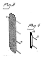
- Fig. 3 illustrates an embodiment of a current supplier for the electrode chamber units in accordance with the invention, more specifically an expanded metal net 17 with rod-like elements 18.
- This embodiment of the current supplier is the one illustrated in Fig. 1, where the net thus has reference numeral 6 and the rods the numeral 7. In this case the net is of substantially the same shape as the central opening 4 in the frame 3.
- Fig. 4 illustrates another variation of the current supplier with a considerably smaller tongue 19 having rod-like elements 20 connected thereto, i.e. the tongue is intended to occupy only a portion of the central opening in the frame.
- the feed solution was stored at room temperature in a polyethylene container having a volume of 60 liters.
- the solution was pumped into the cell by a centrifugal pump via a calibrated flow meter (rotameter). The flow rate was regulated by a valve on the pump pressure side.
- the metal concentrations in the feed solution and the discharge solution were determined with the aid of an atom absorption spectrophotometer (Varion AA-275).
- the pH of said feed and discharge solutions were measured with a glass electrode.
- the recirculating anode solution was a 0.1 M K Z S0 4 solution.
- the anode reaction was a generation of oxygen.
- the solution was allowed to pass through the particulate bed in a single pass.
Landscapes
- Chemical & Material Sciences (AREA)
- Engineering & Computer Science (AREA)
- Chemical Kinetics & Catalysis (AREA)
- Electrochemistry (AREA)
- Organic Chemistry (AREA)
- Materials Engineering (AREA)
- Metallurgy (AREA)
- Life Sciences & Earth Sciences (AREA)
- General Chemical & Material Sciences (AREA)
- Hydrology & Water Resources (AREA)
- Environmental & Geological Engineering (AREA)
- Water Supply & Treatment (AREA)
- Water Treatment By Electricity Or Magnetism (AREA)
- Hybrid Cells (AREA)
- Electrolytic Production Of Metals (AREA)
- Battery Electrode And Active Subsutance (AREA)
- Secondary Cells (AREA)
Abstract
Description
- The present invention relates to the field of electrochemical cells, particularly electrolytic cells, which contain at least one porous percolation electrode in the form of a bed of electrically conductive particles. More specifically the invention relates to a structure of an electrode in the form of a bed of conductive grains, or rather to a complete electrode chamber unit which can very easily be assembled into an electrochemical cell of the filter press configuration. The invention relates to the field of electrode chamber units in the form of beds of conductive grains, and it is simple to construct electrochemical cells with the desired number of units, with the desired thickness of the respective electrodes, with counter electrodes with the same structure as the electrode chamber units or counter electrodes of another type, e.g. solid plates etc., which in turn enables a simple disassembling of the cell, exchange or regeneration of individual electrodes, adjustment of cell structure and size to the intended field of use etc.
- The invention further relates to an electrochemical cell including the above-mentioned electrode chamber units and to a method of producing such an electrochemical cell.
- The discharge of heavy metals in different waste-waters contaminates the surface water and disturbs the biological purification processes in municipal sewage plants. The dominating purification technique currently used is chemical precipitation of the metals as hydroxides. Hydroxide sludge is obtained as a final product, which results in transport and deposition costs. Metal ions have been replaced by sodium or calcium ions in the wastewater, which further means that this salt-bearing water cannot be returned to the process.
- The ideal method of purifying wastewaters containing heavy metals would be a precipitation of the metals in a pure form with simultaneous desalination of the water to a purity allowing recycling in the process. The present invention enables an electrolytic metal precipitation which gives these advantages. Electrolytic metal precipitation from diluted solutions has previously not come into industrial use, due to the fact that conventional electrolysis with planar electrodes requires too large electrode areas to give a satisfactory purification effect, with the low final contents which are required these days (approximately 1 ppm). Under these conditions the electrolysis process is controlled by the transport of metal ions to the electrode surface (the cathode). To achieve a high material transport rate per volumetric unit, and thereby a small reactor volume, the cathode can instead be formed in accordance with the invention as a percolated porous body or a stable particulate bed with a high specific area.
- The basic principle of using beds of conductive grains as electrodes to obtain high specific areas is indeed described 'in the literature..In this connection reference is made to e.g. DOS 2,622,497, DOS 2,904,539, US 3,974,049, 3,859,195, 3,459,646, 3,647,653 and 3,650,925 and DE 2,424,091, 2,620,792, 2,705,007 and 2,723,708 and US 4,123,340 and 4,217,191 and SE 413,446. However, none of these more or less sophisticated structures should be particularly suitable for industrial application with the severe requirements now made on wastewaters, and the structures are furthermore so fixed in thier constructions that they cannot be adapted or modified simply and easily to different applications or conditions, as is the case with the electrode chamber units in accordance with the present invention. Furthermore, EP 122,736 published 24.10.84, mentions the use of electrically conductive particles in connection with a filter press electrochemical cell.
- Cell structures of the filter press type are indeed also known, reference e.g. being made to US 4,274,939 and to DE-A-2948579, but in these cases the electrodes are of completely different structures, viz. in the form of solid plates or hanging carbon fibers respectively, which structures cannot possibly be compared with the beds of conductive grains which have so far been used within the field of porous percolation electrodes. Other examples of frames with solid electrodes are those disclosed in DE 3,221,371 A1 and SU 619 551.
- The art of using a bed of conductive grains as a percolation electrode must be considered specifically distinct from the art of using planar electrodes. Frames with planar electrodes have been known for a long time.
- This document in one embodiment sets forth a method and device wherein packed bed technology is combined with a thin sheet filter press arrangement.
- The present invention has been found particularly usable in conjunction with the purification of wastewaters, e.g. washing water from the galvanizing industry, or mine water, but the new electrode chamber units and cells are by no means limited to just this use, but one of the great advantages of the invention is just that electrochemical cells can be tailored for practically any kind of electrochemical reaction of the electrolysis type. The current conductors of the electrode chamber units according to the invention can be implemented in different ways, most important, however, being that they do not disturb the electrolyte flow through the bed to any appreciable extent.
- The electrode chamber unit in accordance with the invention includes at least one substantially flat frame having a thickness within the range of 0.2-5 cm and defining a central opening that is filled with the electrically conductive grains so that these form a flat porous bed within said opening, the grains being kept in place within the central opening of the frame by sufficiently dense separators, which are arranged to cover the central opening on either side of the frame to form an electrode chamber, the frame being provided with at least one hole for supply and at least one hole for discharge of electrolyte, where said holes are in communication via inlet and outlet channels respectively with the central opening of the frame, and the frame including current conductors for the supply of electric current to the conductive particles via said frame, said current conductors comprising an electrode element located within said bed which element is a substantially flat tongue arranged with a space to the edge of the central opening or a metal net the dimensions of which are similar to or smaller than the dimensions of the central opening, and conducting means inserted through the peripheral edge of the frame.
- By the expression "at least one frame" it is to be understood in the present case that an alternative to a thick frame is two or more thinner frames, which make it possible to work with one and the same frame thickness but still vary the thickness of the electrode. In such a case the frames are placed against each other and can be regarded in relation to the remaining components of the electrode chamber unit as a single cohesive frame, the term "frame" being used for the sake of simplicity even in the cases where two or more frames are used in one and the same electrode.
- However, both the frame and the separators are preferably made in a polymeric material, thus enabling the achievement of the above-mentioned advantages, particularly if this polymeric material is a thermoplastic, injection mouldable material. The material for the frame and the separators respectively does not necessarily need to be the same polymeric material. Thus, polyethylene and polypropylene can be mentioned as examples of suitable materials for the frame, whereas the separator, if made from another material than the frame, can be moulded e.g. from polyamide or polyester. In this connection it can also be mentioned that in the applications requiring ion-selective diaphragms, these diaphragms can also function as separators. Thus, in this case the diaphragm has a double function. Separate diaphragms can be used of course, which is illustrated more closely below.
- Since one and the same frame of the electrode chamber unit in accordance with the invention contains holes for the supply as well as holes for the discharge of electrolyte, an electrochemical cell made up from the electrode chamber units will function in a way where the electric current and electrolyte flow are directed in a cross-flow pattern in relation to each other, which has been found to give considerably better performance than in those cases where the electric current and electrolyte flow are directed in a concurrent or countercurrent flow in relation to each other.
- The central opening of the frame, and thereby the electrode bed, can be given different configurations, but it has been found that particularly favourable flow conditions and performances are achieved if the central opening has a substantially rectangular shape. The ratio longside:shortside of the rectangle is suitably at least 2:1 and preferably at least 4:1, a particularly favourable range being 4:1-10:1. Furthermore, if the channels for supply and discharge of electrolyte to and from the central opening open out in the respective shortside of the rectangle, i.e. at opposing shortsides, advantageous conditions for the electrolysis are achieved.
- Particularly in the case of metal recovery from diluted solutions, there is a requirement for low ohmic losses and the avoidance of secondary reactions, apart from the requirement of a large electrode surface per unit of volume and good material transfer, which are met by the electrode chamber unit in accordance with the invention. In turn, this means that the thickness of the electrode frame, and thereby of the electrode, should be kept comparatively small compared with the length and width, respectively, of the frame. In absolute numbers this more specifically means that the frame generally has a thickness within the range of 0.2-5 cm, more preferably 0.5-2 cm and most preferably 0.5-1 cm. By the structure of the new units in accordance with the invention, as well as the opportunity of assembling electrochemical cells with the desired capacities by assembling a desired number of frames, the small bed thickness does not involve any disadvantage.
- With regard to the electrode material, the requirements of the particulate electrode are the following: a good electrical conductor, chemically inert, usable both as a cathode and an anode and cheapness. The material which presently has shown to meet these demands in the best way is graphite, which is thus the preferred material for the conductive particles, but the invention is of course not limited to the use of this material only, since the idea is applicable to all other materials with similar properties.
- The size of the electrically conductive particles is easily determined by one skilled in the art for each individual case, depending on the particular conditions applying to the application in question. In general, however, the risk of channel formations and the requirement of reasonable pressure drops contradict too small particles or grains in the bed. A balance must be struck with the requirement of high specific area, which grows inversely proportional to the particle size. A usable range for particle size is, however, 0.5-5 mm, preferably 1-2 mm. Furthermore, the best purification conditions have been found to occur when the particles have an irregular shape, this being often preferable to a homogeneous spherical shape.
- An important demand on the electrode chamber units is that they give good mutual sealing in the electrochemical cell in which they are incorporated. For this reason the frame should preferably be surrounded on either side by a separate gasket, which is suitably a planar or flat gasket. Apart from its purely sealing function, the gasket can also have the function of regulating the packing density of the bed of the electrically conductive particles. This means that the gasket is preferably manufactured from a soft or elastic material, e.g. rubber, which can be compressed, or allowed to expand, respectively, in response to how tightly it is required to pack the bed.
- To enable the cell to operate as a continuous concentrator, where large volumes of low-concentrated waste solution are refined into small volumes of highly concentrated metal solution, there is further required in this special application dense and effective ion-selective diaphragms, i.e. in this case anion-selective diaphragms. In order that this diaphragm will not be punctured by the particles in the bed it is suitably disposed such that it is protected by the separator. In accordance with a preferable embodiment this is done by selecting as the separator a net or fabric or cloth material, preferably a polymeric material which surrounds the diaphragm on both sides. The separator net or fabric must be so dense as to protect the diaphragm from said puncturing by the electrically conductive particles, while at the same time not being so dense as to disturb the electrolytic current.
- Current supply via the frame is required to the electrically conductive particle bed. The current conductors can be implemented in different ways, most important being that they do not disturb the electrolyte flow through the bed to any appreciable extent. As was mentioned above one embodiment of current supplier which has been found to fulfil this requirement is one in the form of a substantially flat tongue arranged in the bed of conductive particles, the tongue being connectable to a current source via bar-like elements, preferably of a substantially circular cross-section which are inserted through the peripheral edge of the frame. It has been found that the tongue should be thrust a distance into the bed, i.e. with a space to the edge of the central opening of the frame, whereby the electrolyte flow is disturbed as little as possible. A particularly preferred combination of materials in this case is a graphite tongue with rodlike elements of titanium. Another embodiment of current conductor which has also been found effective is a large-mesh metal net, e.g. expanded metal of titanium, arranged inside the bed, its dimensions being similar to or smaller than the dimensions of the central opening of the frame.
- For the supply of electrolyte from the holes of the frame to its central opening there is at least one channel. In accordance with a preferable embodiment of the invention, this channel contains means enabling the electrolyte to be distributed over the entire width of the central opening of the frame, so that the electrolyte flow will be uniform over the entire bed. According to a variant, these means are several smaller channels, but other embodiments of such distribution or throttling means are conceivable. In the corresponding way, the channel for discharge of electrolyte from the particle bed is suitably provided with similar distribution means.
- Another particularly preferable embodiment of the electrode chamber unit in accordance with the invention is represented by the case where the frame has two holes for the inlet and two holes for the discharge of electrolyte with separate channels from both holes to the central opening. If these channels are arranged to open out on opposite sides of the central opening, this means that one and the same frame is usable both as an anode and a cathode in the cell, by rotating the anode or cathode frames by 180° in relation to each other. The thickness of each electrode can be varied discretely by several frames with the same orientations and without intermediate separators being assembled into a common thicker electrode frame.
- The invention further relates to an electrochemical cell, which includes or is constructed solely from the above-described electrode chamber units. The electrochemical cell in accordance with the invention is thus constructed according to the filter press principle with electrodes being arranged in central openings in frames provided with holes for supply and discharge of electrolyte respectively to and from the electrode. At least one kind of electrode (anode or cathode) consequently consists of porous percolating electrodes, while the counter electrodes can be solid or sintered plates arranged in similar or identical frames.
- In the cases where the anodes as well as the cathodes are to be porous percolation electrodes, the electrode chamber units mentioned above, which have two holes for inlet and two holes for discharge of electrolyte are suitably used, the frames being turned 180° in relation to each other.
- In the electrochemical cell according to the invention the shortside of the central opening, in the case where the central opening is a rectangle, is arranged along a horizontal plane. By this the electrolyte flow will be directed upwardly or downwardly in the vertical plane.
- It will be seen from the above that the expression "electrochemical cell" is used in a broad sense, i.e. not in the sense of a single cell with only one anode and one cathode, but a cell with the desired number of anodes and cathodes. Synonymous expressions in conjunction with the present invention are thus "electrochemical reactor" or "electrolysis apparatus".
- The term "separator" in the present case also intends to convey a broad meaning which means that the separator is not necessarily arranged between two electrodes, but ultimately it may also constitute the end plate of the cell and "separate" the outermost electrode from the surroundings.
- According to another aspect of the present invention, a method is provided for producing or assembling the electrochemical cell described above. Distinguishing for this method is that a separator is placed horizontally, the first separator according to the definition above usually consisting of the end plate of the cell, that at least one frame is placed on top of the separator; that the central opening of the frame is filled with the particles of the electrically conductive material; that the next separator is placed thereupon so as to keep the particles in place; and then optionally an ion-selective diaphragm or membrane; and on top thereof another separator, and that the procedure is repeated with the number of electrode chamber units which are to be included in the electrochemical cell, the units then being locked together with conventional locking or clamping means.
- In agreement with what has been discussed above, gaskets of an elastic material, e.g. rubber, are used between the frames in accordance with a preferred embodiment of the method, the central opening being filled with the conductive particles up to the edge of the gasket, and the gaskets being compressed to obtain the desired packing density for the conductive particles. This compression, together with the above-mentioned locking, can e.g. be made with through-going metal rods with screwed ends for nuts. Another example of the clamping means are so-called snap-on means, by which the plastic frames can be connected to each other, although these means can be more difficult to implement as compression means.
- The electrochemical cell in accordance with the invention is especially useful for the purification of wastewaters, particularly for the purification of water contaminated by heavy metals.
- However, the cell claimed is by no means limited to this particular use, one of the great advantages of the invention being instead the new possibilities of tailoring an electrochemical cell for practically every type of electrochemical reaction. Other examples of fields of uses will be illustrated below and can moreover be easily worked out by one skilled in the art. The size of the cell can be simply adjusted to the needs by selection of a suitable number of frames, where each frame is built up for a given capacity. To increase the total reliability and reduce the risks of leakage it may be advisable not to make the individual modules too large. The desired size of the plant can be obtained instead by a connection in parallel of several modules or by a connection in series of parallel modules. Among further advantages in this connection there can be mentioned doubled electrolyte speed in the electrodes for the same total residence time in the system, which gives an improved material transport, and that the lower current loading in the second step means that the electrode thickness can be increased and the total diaphragm area thereby decreased. The electrode thickness can be increased in discrete steps by putting together several frames for each electrode.
- The invention will now be disclosed more in detail with reference to the accompanying drawings, on which
- Fig. 1 is a so-called exploded view of an electrochemical cell in accordance with the invention, constructed according to the filter press principle and containing an embodiment of the electrode chamber unit in accordance with the invention;
- Fig. 2 illustrates the cell of Fig. 1 in the assembled condition;
- Fig. 3 illustrates an embodiment of a current conductor intended for use in the electrode chamber unit in accordance with the invention; and
- Fig. 4 illustrates another embodiment of a current conductor for use in the electrode chamber unit in accordance with the invention.
- The cell illustrated by an exploded view in Fig. 1 contains a number of cathodes 1 and
anodes 2, which are of the same principle structures. The electrode as well as the counter electrode are built up from a frame 3 with a rectangular form defining acentral opening 4, which is also of a substantially rectangular shape, although the rectangle has oblique corners for providing a more homogeneous electrolyte flow across the electrode. Thecentral opening 4 is filled with a porous bed 5 of electrically conductive particles. This bed 5 covers substantially theentire opening 4, but for the sake of clarity only part thereof is shown in the Figure. The reason for this is that the Figure also shows the current conductor 6. In the illustrated case this conductor 6 is an expanded metal net embedded in the particle bed 5. Rod-like members 7 furthermore project via the edge of the frame 3 for supply of current to the metal net 6. In the illustrated embodiment, the elements 7 from the cathodes are directed towards the viewer, while the corresponding elements from the anodes are not visible but are directed in the opposite direction, so that it will be simpler to keep apart the current conductors to the respective kind of electrode. Each frame is furthermore provided with two holes 8 for inlet and twoholes 9 for discharge of electrolyte. In the illustrated case, the electrolyte is fed to the cathodes 1 via the right hand hole 8 while it is fed to theanodes 2 via the left hand hole 8. The arrow drawn in full thus represents the electrolyte flow to and from the cathodes while the arrow drawn with a dashed line represents the corresponding flow to and from the anodes. - On either sides of each cathode 1 and each
anode 2 there is aseparator net 10 of the same configuration as the central opening of the respective electrode. This net 10 is surrounded by agasket 11 of an elastic material, said gasket enabling regulation of the packing density for the particles of the conductive material. - In the illustrated embodiment the electrode chamber unit also includes an ion-
selective diaphragm 12 arranged between twoseparators 10. - As will be seen from the Figure, the
gaskets 11 anddiaphragm 12 are also provided with electrolyte passage holes in register with theholes 8 and 9, respectively, in the electrodes. - The cell from Fig. 1 is illustrated in Fig. 2 in an assembled state, additional illustrated details being
end plates 13, e.g. of metal, with inlet holes 14 and outlet holes (not visible) for electrolyte,rods 15 andnuts 16 for clamping the cell together in an assembled condition. As is clear from the above description, theend plates 13 are called separators forthe sake of simplicity and forthe purpose of the invention, although they have a different structure and partially another function than theseparators 10. - Fig. 3 illustrates an embodiment of a current supplier for the electrode chamber units in accordance with the invention, more specifically an expanded
metal net 17 with rod-like elements 18. This embodiment of the current supplier is the one illustrated in Fig. 1, where the net thus has reference numeral 6 and the rods the numeral 7. In this case the net is of substantially the same shape as thecentral opening 4 in the frame 3. - Fig. 4 illustrates another variation of the current supplier with a considerably
smaller tongue 19 having rod-like elements 20 connected thereto, i.e. the tongue is intended to occupy only a portion of the central opening in the frame. - The invention is finally illustrated by the following non-restricting working examples.
- The experiments were carried out while varying the following parameters: input concentration, kind of metal ion, flow rate, graphite grain size and electrolyte resistivity. Most of the experiments were carried out with a single particulate electrode of the type described, closed in on either side by an anion-selective diaphragm (Selemion ASV from Asahi Glass, Japan) and counter electrodes of lead plates. A polypropylene net was also applied as a separator between the lead electrodes and the diaphragms. Experiments were also carried out with several particulate electrodes (four, every second cathodic and every second anodic) according to Fig. 1.
- The feed solution was stored at room temperature in a polyethylene container having a volume of 60 liters. The solution was pumped into the cell by a centrifugal pump via a calibrated flow meter (rotameter). The flow rate was regulated by a valve on the pump pressure side. The metal concentrations in the feed solution and the discharge solution were determined with the aid of an atom absorption spectrophotometer (Varion AA-275). The pH of said feed and discharge solutions were measured with a glass electrode.
- The recirculating anode solution was a 0.1 M KZS04 solution. The anode reaction was a generation of oxygen.
- The solution was allowed to pass through the particulate bed in a single pass.
- Experiments were made with both synthetic solutions made up from KsS04 (0.1-0.5 M) solutions and CUS04 to the desired concentration, and authentic waste solutions from the surface finishing industry.
- The results are apparent from Table 1 below.

- Due to the very non-precious nature of zinc (electrode potential=-0.76 V relative to a hydrogen gas electrode) an electrochemical precipitation of zinc is very difficult. A series of experiments with different pH:s were carried out. The results are presented in Table 2:

- As expected, the purification effect was not as good as for copper. The higher the pH value the better is the purification.
- With very dilute solutions the electrolyte resistivity can be very low. A trial series was therefore carried out with varying contents of supporting electrolyte in the precipitation of copper.
- The results are accounted for in Table 3 (dp=1.2 mm).

- Experiments were also made with a complete cell consisting of two particulate anodes and two particulate cathodes; see Fig. 1. The same experimental procedure was used as above. The experiments embraced copper precipitation only. The results corresponded substantially to those in Table 1.
Claims (23)
Priority Applications (1)
| Application Number | Priority Date | Filing Date | Title |
|---|---|---|---|
| AT84850183T ATE46722T1 (en) | 1983-06-17 | 1984-06-13 | ELECTRODE CHAMBER UNIT FOR AN ELECTROCHEMICAL CELL WITH A POROUS FILTER ELECTRODE. |
Applications Claiming Priority (2)
| Application Number | Priority Date | Filing Date | Title |
|---|---|---|---|
| SE8303494A SE451855B (en) | 1983-06-17 | 1983-06-17 | ELECTROCEDOM CELL UNIT INTENDED TO BE USED IN AN ELECTROCHEMICAL CELL WITH PORO'S FLOW ELECTRODE, ELECTROCHEMICAL CELL, PROCEDURE FOR THE PREPARATION OF THE ELECTROCHEMICAL CELL AND USED FOR USING IT |
| SE8303494 | 1983-06-17 |
Publications (2)
| Publication Number | Publication Date |
|---|---|
| EP0129523A1 EP0129523A1 (en) | 1984-12-27 |
| EP0129523B1 true EP0129523B1 (en) | 1989-09-27 |
Family
ID=20351667
Family Applications (1)
| Application Number | Title | Priority Date | Filing Date |
|---|---|---|---|
| EP84850183A Expired EP0129523B1 (en) | 1983-06-17 | 1984-06-13 | An electrode chamber unit intended for an electrochemical cell having a porous percolation electrode |
Country Status (7)
| Country | Link |
|---|---|
| US (1) | US4692229A (en) |
| EP (1) | EP0129523B1 (en) |
| JP (1) | JPS6022987A (en) |
| AT (1) | ATE46722T1 (en) |
| CA (1) | CA1230080A (en) |
| DE (1) | DE3479903D1 (en) |
| SE (1) | SE451855B (en) |
Families Citing this family (16)
| Publication number | Priority date | Publication date | Assignee | Title |
|---|---|---|---|---|
| IT1203373B (en) * | 1987-03-18 | 1989-02-15 | Silvestri Silvestri | DEVICE FOR THE TRANSFORMATION OF ELECTROLYTIC CELLS OF THE FILTER TYPE PRESS IN CELLS WITH CONTINUOUS RENEWABLE SACRIFICAL ELECTRODES |
| US4954228A (en) * | 1987-05-27 | 1990-09-04 | Cheminuest, A.S. | Drum electrolysis |
| NO164921C (en) * | 1987-05-27 | 1990-11-28 | Cheminvest As | PROCEDURE FOR ELECTRICAL EXTRACTION OF METAL AND DEVICE FOR CARRYING OUT THE PROCEDURE. |
| US4770756A (en) * | 1987-07-27 | 1988-09-13 | Olin Corporation | Electrolytic cell apparatus |
| EP0311575A1 (en) * | 1987-10-06 | 1989-04-12 | Siam Trade Equipment Co., Ltd. | Electrolysis cell and method of producing chlorine |
| FI903683A0 (en) * | 1988-11-21 | 1990-07-20 | Uk I Inzh Vodnogo Khoz | ELECTROYSOER FOER VATTENRENING FRAON FLUORHALTIGA INGREDIENSER. |
| DE4000505C1 (en) * | 1990-01-10 | 1991-05-08 | Hoechst Ag, 6230 Frankfurt, De | |
| US5804044A (en) * | 1990-05-07 | 1998-09-08 | Eastman Kodak Company | Electrolysis device and method using a porous electrode |
| US5425858A (en) * | 1994-05-20 | 1995-06-20 | The Regents Of The University Of California | Method and apparatus for capacitive deionization, electrochemical purification, and regeneration of electrodes |
| GB9822958D0 (en) | 1998-10-20 | 1998-12-16 | Adept Technologies As | Reactor for treating liquids |
| US6274028B1 (en) | 1999-04-23 | 2001-08-14 | Clyde Kuen-Hua Hu | Electrolytic wastewater treatment method and apparatus |
| US6814840B2 (en) | 2001-02-14 | 2004-11-09 | National Research Council Of Canada | Flow-through electrochemical reactor for wastewater treatment |
| CN100450937C (en) * | 2007-01-11 | 2009-01-14 | 常州爱思特净化设备有限公司 | Liquid Handling Module |
| US20120118757A1 (en) * | 2010-11-16 | 2012-05-17 | Ronald Charles Mehl | Disposable Electrolytic Cell with Bi-polar Electrode, and Method of Use Thereof |
| MY202878A (en) * | 2018-03-27 | 2024-05-28 | Tokuyama Corp | Electrolysis vessel for alkaline water electrolysis |
| JP7169021B1 (en) * | 2021-12-28 | 2022-11-10 | 株式会社アクト | generator |
Citations (1)
| Publication number | Priority date | Publication date | Assignee | Title |
|---|---|---|---|---|
| EP0122736A1 (en) * | 1983-03-21 | 1984-10-24 | Reilly Industries, Inc. | Filter press electrochemical cell with improved fluid distribution system |
Family Cites Families (19)
| Publication number | Priority date | Publication date | Assignee | Title |
|---|---|---|---|---|
| US1239443A (en) * | 1913-10-31 | 1917-09-11 | Frank L Antisell | Apparatus for electrolytic deposition. |
| US1231967A (en) * | 1914-11-14 | 1917-07-03 | Urlyn Clifton Tainton | Electrolytic recovery of metals from their solutions and in apparatus therefor. |
| US3236760A (en) * | 1959-11-09 | 1966-02-22 | Oronzio De Nora Impianti | Cells for the production of chlorine from hydrochloric acid |
| GB1052569A (en) * | 1964-11-30 | |||
| US3748238A (en) * | 1972-05-08 | 1973-07-24 | Sybron Corp | Electrolytic process for the preparation of sodium hydrosulfite |
| US3954594A (en) * | 1974-09-04 | 1976-05-04 | Rockwell International Corporation | Electrochemical cell for decreasing the cyanide and heavy metal content of an aqueous solution |
| DE2622497C2 (en) * | 1976-05-20 | 1986-03-06 | Dechema Deutsche Gesellschaft für chemisches Apparatewesen e.V., 6000 Frankfurt | Electrochemical cell |
| CH610935A5 (en) * | 1976-09-03 | 1979-05-15 | Battelle Memorial Institute | Electrochemical reactor intended to be incorporated into a plant for the production of titanium dioxide from ilmenite by the sulphate process |
| CA1159008A (en) * | 1978-12-04 | 1983-12-20 | Sankar Das Gupta | Reactor with working and secondary electrodes and polarity reversal means for treating waste water |
| US4226685A (en) * | 1978-10-23 | 1980-10-07 | Kennecott Copper Corporation | Electrolytic treatment of plating wastes |
| DE2904539C2 (en) * | 1979-02-07 | 1982-08-05 | Deutsche Carbone Ag, 6000 Frankfurt | Process for electrolytic wastewater purification by means of a fixed-bed electrolysis cell and electrochemical cell for carrying out the process |
| US4292160A (en) * | 1979-08-20 | 1981-09-29 | Kennecott Corporation | Apparatus for electrochemical removal of heavy metals such as chromium from dilute wastewater streams using flow-through porous electrodes |
| US4367132A (en) * | 1980-08-27 | 1983-01-04 | Electro-Petroleum, Inc. | Method for removing liquid from chemically-precipitated sludge |
| US4357224A (en) * | 1981-04-07 | 1982-11-02 | Westinghouse Electric Corp. | Energy efficient electrolyzer for the production of hydrogen |
| US4445990A (en) * | 1981-11-12 | 1984-05-01 | General Electric Company | Electrolytic reactor for cleaning wastewater |
| US4430176A (en) * | 1981-11-13 | 1984-02-07 | Occidental Chemical Corporation | Electrolytic process for producing hydrogen peroxide |
| US4585539A (en) * | 1982-08-17 | 1986-04-29 | Technic, Inc. | Electrolytic reactor |
| IL68773A0 (en) * | 1983-05-24 | 1983-12-30 | Yeda Res & Dev | Modular electrodialysis device |
| US4564432A (en) * | 1983-07-25 | 1986-01-14 | Nanao Kogyo Co., Ltd. | Apparatus for recovering metals dissolved in a solution |
-
1983
- 1983-06-17 SE SE8303494A patent/SE451855B/en not_active IP Right Cessation
-
1984
- 1984-06-13 AT AT84850183T patent/ATE46722T1/en not_active IP Right Cessation
- 1984-06-13 DE DE8484850183T patent/DE3479903D1/en not_active Expired
- 1984-06-13 EP EP84850183A patent/EP0129523B1/en not_active Expired
- 1984-06-15 US US06/621,101 patent/US4692229A/en not_active Expired - Fee Related
- 1984-06-15 CA CA000456746A patent/CA1230080A/en not_active Expired
- 1984-06-15 JP JP59123562A patent/JPS6022987A/en active Pending
Patent Citations (1)
| Publication number | Priority date | Publication date | Assignee | Title |
|---|---|---|---|---|
| EP0122736A1 (en) * | 1983-03-21 | 1984-10-24 | Reilly Industries, Inc. | Filter press electrochemical cell with improved fluid distribution system |
Also Published As
| Publication number | Publication date |
|---|---|
| JPS6022987A (en) | 1985-02-05 |
| ATE46722T1 (en) | 1989-10-15 |
| US4692229A (en) | 1987-09-08 |
| SE451855B (en) | 1987-11-02 |
| EP0129523A1 (en) | 1984-12-27 |
| SE8303494D0 (en) | 1983-06-17 |
| SE8303494L (en) | 1984-12-18 |
| DE3479903D1 (en) | 1989-11-02 |
| CA1230080A (en) | 1987-12-08 |
Similar Documents
| Publication | Publication Date | Title |
|---|---|---|
| US4692229A (en) | Electrode chamber unit for an electro-chemical cell having a porous percolation electrode | |
| US4585539A (en) | Electrolytic reactor | |
| CA1159008A (en) | Reactor with working and secondary electrodes and polarity reversal means for treating waste water | |
| US3919062A (en) | Electrochemical system graduated porous bed sections | |
| US6254762B1 (en) | Process and electrolytic cell for producing hydrogen peroxide | |
| US4834850A (en) | Efficient electrolytic precious metal recovery system | |
| KR100455052B1 (en) | Water treatment method of treated water containing ruins | |
| US3977951A (en) | Electrolytic cells and process for treating dilute waste solutions | |
| US6298996B1 (en) | Three dimensional electrode for the electrolytic removal of contaminants from aqueous waste streams | |
| EP1115909A2 (en) | Flow-through capacitor and method of treating liquids with it | |
| CA1106312A (en) | Electrolytic cell with membrane | |
| CN110217866B (en) | Electrodialysis device and method for treating stainless steel pickling wastewater by using electrodialysis device | |
| WO2024155380A1 (en) | Systems and methods for electrochemical generation of acid and base | |
| US5911859A (en) | Three-dimensional electrode (Law464) | |
| US4981563A (en) | Electrolysis cell and method of producing chlorine | |
| KR200283468Y1 (en) | Water electrolysis cell and electrolysis system using it | |
| CN207047333U (en) | A kind of multistage infiltration electrolysis machine | |
| US5637206A (en) | Process for the electrochemical production of ammonium polysulfide | |
| KR102616273B1 (en) | Apparatus of generating electrolyzed water | |
| CA1050478A (en) | Electrolytic cells | |
| IE37684L (en) | Electrolytic cell having a fluid bed electrode | |
| GB2077294A (en) | Horizontal diaphragmless bipolar brine electrolyzer | |
| Kreysa | Reactor design for electrochemical water treatment | |
| JPS641961Y2 (en) | ||
| JPH10146588A (en) | Apparatus and method for water treatment |
Legal Events
| Date | Code | Title | Description |
|---|---|---|---|
| PUAI | Public reference made under article 153(3) epc to a published international application that has entered the european phase |
Free format text: ORIGINAL CODE: 0009012 |
|
| AK | Designated contracting states |
Designated state(s): AT BE CH DE FR GB IT LI LU NL SE |
|
| 17P | Request for examination filed |
Effective date: 19850607 |
|
| 17Q | First examination report despatched |
Effective date: 19860307 |
|
| RAP1 | Party data changed (applicant data changed or rights of an application transferred) |
Owner name: ELECTROCELL SYSTEMS AB |
|
| GRAA | (expected) grant |
Free format text: ORIGINAL CODE: 0009210 |
|
| AK | Designated contracting states |
Kind code of ref document: B1 Designated state(s): AT BE CH DE FR GB IT LI LU NL SE |
|
| ITF | It: translation for a ep patent filed | ||
| PG25 | Lapsed in a contracting state [announced via postgrant information from national office to epo] |
Ref country code: SE Effective date: 19890927 Ref country code: NL Effective date: 19890927 Ref country code: BE Effective date: 19890927 Ref country code: AT Effective date: 19890927 |
|
| REF | Corresponds to: |
Ref document number: 46722 Country of ref document: AT Date of ref document: 19891015 Kind code of ref document: T |
|
| ET | Fr: translation filed | ||
| REF | Corresponds to: |
Ref document number: 3479903 Country of ref document: DE Date of ref document: 19891102 |
|
| NLV1 | Nl: lapsed or annulled due to failure to fulfill the requirements of art. 29p and 29m of the patents act | ||
| PG25 | Lapsed in a contracting state [announced via postgrant information from national office to epo] |
Ref country code: LU Free format text: LAPSE BECAUSE OF NON-PAYMENT OF DUE FEES Effective date: 19900630 |
|
| PLBE | No opposition filed within time limit |
Free format text: ORIGINAL CODE: 0009261 |
|
| STAA | Information on the status of an ep patent application or granted ep patent |
Free format text: STATUS: NO OPPOSITION FILED WITHIN TIME LIMIT |
|
| 26N | No opposition filed | ||
| ITTA | It: last paid annual fee | ||
| PGFP | Annual fee paid to national office [announced via postgrant information from national office to epo] |
Ref country code: GB Payment date: 19970523 Year of fee payment: 14 |
|
| PGFP | Annual fee paid to national office [announced via postgrant information from national office to epo] |
Ref country code: FR Payment date: 19970620 Year of fee payment: 14 |
|
| PGFP | Annual fee paid to national office [announced via postgrant information from national office to epo] |
Ref country code: DE Payment date: 19970621 Year of fee payment: 14 |
|
| PGFP | Annual fee paid to national office [announced via postgrant information from national office to epo] |
Ref country code: CH Payment date: 19970627 Year of fee payment: 14 |
|
| PG25 | Lapsed in a contracting state [announced via postgrant information from national office to epo] |
Ref country code: GB Free format text: LAPSE BECAUSE OF NON-PAYMENT OF DUE FEES Effective date: 19980613 |
|
| PG25 | Lapsed in a contracting state [announced via postgrant information from national office to epo] |
Ref country code: LI Free format text: LAPSE BECAUSE OF NON-PAYMENT OF DUE FEES Effective date: 19980630 Ref country code: CH Free format text: LAPSE BECAUSE OF NON-PAYMENT OF DUE FEES Effective date: 19980630 |
|
| GBPC | Gb: european patent ceased through non-payment of renewal fee |
Effective date: 19980613 |
|
| REG | Reference to a national code |
Ref country code: CH Ref legal event code: PL |
|
| PG25 | Lapsed in a contracting state [announced via postgrant information from national office to epo] |
Ref country code: FR Free format text: LAPSE BECAUSE OF NON-PAYMENT OF DUE FEES Effective date: 19990226 |
|
| PG25 | Lapsed in a contracting state [announced via postgrant information from national office to epo] |
Ref country code: DE Free format text: LAPSE BECAUSE OF NON-PAYMENT OF DUE FEES Effective date: 19990401 |
|
| REG | Reference to a national code |
Ref country code: FR Ref legal event code: ST |