EP0129444B2 - Methods for obtaining high-purity carbon monoxide - Google Patents
Methods for obtaining high-purity carbon monoxide Download PDFInfo
- Publication number
- EP0129444B2 EP0129444B2 EP84304148A EP84304148A EP0129444B2 EP 0129444 B2 EP0129444 B2 EP 0129444B2 EP 84304148 A EP84304148 A EP 84304148A EP 84304148 A EP84304148 A EP 84304148A EP 0129444 B2 EP0129444 B2 EP 0129444B2
- Authority
- EP
- European Patent Office
- Prior art keywords
- adsorption
- column
- stage
- gas
- columns
- Prior art date
- Legal status (The legal status is an assumption and is not a legal conclusion. Google has not performed a legal analysis and makes no representation as to the accuracy of the status listed.)
- Expired - Lifetime
Links
- 238000000034 method Methods 0.000 title claims description 33
- 229910002091 carbon monoxide Inorganic materials 0.000 title claims description 31
- UGFAIRIUMAVXCW-UHFFFAOYSA-N Carbon monoxide Chemical compound [O+]#[C-] UGFAIRIUMAVXCW-UHFFFAOYSA-N 0.000 title claims description 28
- 238000001179 sorption measurement Methods 0.000 claims description 148
- 239000007789 gas Substances 0.000 claims description 138
- CURLTUGMZLYLDI-UHFFFAOYSA-N Carbon dioxide Chemical compound O=C=O CURLTUGMZLYLDI-UHFFFAOYSA-N 0.000 claims description 86
- 229910002092 carbon dioxide Inorganic materials 0.000 claims description 43
- 238000010926 purge Methods 0.000 claims description 33
- 239000003463 adsorbent Substances 0.000 claims description 26
- 239000001569 carbon dioxide Substances 0.000 claims description 20
- 239000000203 mixture Substances 0.000 claims description 13
- 239000008246 gaseous mixture Substances 0.000 claims description 9
- 239000002912 waste gas Substances 0.000 claims description 9
- 230000001747 exhibiting effect Effects 0.000 claims description 7
- 238000003795 desorption Methods 0.000 claims description 2
- 238000007599 discharging Methods 0.000 claims 1
- 239000000047 product Substances 0.000 description 29
- IJGRMHOSHXDMSA-UHFFFAOYSA-N Atomic nitrogen Chemical compound N#N IJGRMHOSHXDMSA-UHFFFAOYSA-N 0.000 description 24
- 229910052757 nitrogen Inorganic materials 0.000 description 10
- XEEYBQQBJWHFJM-UHFFFAOYSA-N Iron Chemical compound [Fe] XEEYBQQBJWHFJM-UHFFFAOYSA-N 0.000 description 8
- HNPSIPDUKPIQMN-UHFFFAOYSA-N dioxosilane;oxo(oxoalumanyloxy)alumane Chemical class O=[Si]=O.O=[Al]O[Al]=O HNPSIPDUKPIQMN-UHFFFAOYSA-N 0.000 description 7
- 238000007670 refining Methods 0.000 description 6
- 238000000926 separation method Methods 0.000 description 6
- 229910021536 Zeolite Inorganic materials 0.000 description 5
- 239000006227 byproduct Substances 0.000 description 5
- 239000010457 zeolite Substances 0.000 description 5
- XKRFYHLGVUSROY-UHFFFAOYSA-N Argon Chemical compound [Ar] XKRFYHLGVUSROY-UHFFFAOYSA-N 0.000 description 4
- OKTJSMMVPCPJKN-UHFFFAOYSA-N Carbon Chemical compound [C] OKTJSMMVPCPJKN-UHFFFAOYSA-N 0.000 description 4
- 229910052742 iron Inorganic materials 0.000 description 4
- VNWKTOKETHGBQD-UHFFFAOYSA-N methane Chemical compound C VNWKTOKETHGBQD-UHFFFAOYSA-N 0.000 description 4
- 238000006243 chemical reaction Methods 0.000 description 3
- 238000007710 freezing Methods 0.000 description 3
- 229910052751 metal Inorganic materials 0.000 description 3
- 239000002184 metal Substances 0.000 description 3
- 239000008188 pellet Substances 0.000 description 3
- 239000000126 substance Substances 0.000 description 3
- 238000003786 synthesis reaction Methods 0.000 description 3
- 229910000831 Steel Inorganic materials 0.000 description 2
- 238000010521 absorption reaction Methods 0.000 description 2
- 229910052786 argon Inorganic materials 0.000 description 2
- 230000015572 biosynthetic process Effects 0.000 description 2
- 229910052680 mordenite Inorganic materials 0.000 description 2
- MWUXSHHQAYIFBG-UHFFFAOYSA-N nitrogen oxide Inorganic materials O=[N] MWUXSHHQAYIFBG-UHFFFAOYSA-N 0.000 description 2
- 230000003647 oxidation Effects 0.000 description 2
- 238000007254 oxidation reaction Methods 0.000 description 2
- 239000002245 particle Substances 0.000 description 2
- 238000011084 recovery Methods 0.000 description 2
- 239000010959 steel Substances 0.000 description 2
- 239000004215 Carbon black (E152) Substances 0.000 description 1
- RYGMFSIKBFXOCR-UHFFFAOYSA-N Copper Chemical compound [Cu] RYGMFSIKBFXOCR-UHFFFAOYSA-N 0.000 description 1
- UFHFLCQGNIYNRP-UHFFFAOYSA-N Hydrogen Chemical compound [H][H] UFHFLCQGNIYNRP-UHFFFAOYSA-N 0.000 description 1
- 239000002250 absorbent Substances 0.000 description 1
- 230000002745 absorbent Effects 0.000 description 1
- -1 activated carbon Chemical compound 0.000 description 1
- 230000000274 adsorptive effect Effects 0.000 description 1
- 239000011230 binding agent Substances 0.000 description 1
- 238000009835 boiling Methods 0.000 description 1
- 230000000052 comparative effect Effects 0.000 description 1
- 229910052802 copper Inorganic materials 0.000 description 1
- 239000010949 copper Substances 0.000 description 1
- 230000003247 decreasing effect Effects 0.000 description 1
- 239000000446 fuel Substances 0.000 description 1
- 238000000227 grinding Methods 0.000 description 1
- 229930195733 hydrocarbon Natural products 0.000 description 1
- 150000002430 hydrocarbons Chemical class 0.000 description 1
- 239000001257 hydrogen Substances 0.000 description 1
- 229910052739 hydrogen Inorganic materials 0.000 description 1
- 230000004048 modification Effects 0.000 description 1
- 238000012986 modification Methods 0.000 description 1
- 239000002808 molecular sieve Substances 0.000 description 1
- 239000003345 natural gas Substances 0.000 description 1
- 239000003921 oil Substances 0.000 description 1
- 230000001590 oxidative effect Effects 0.000 description 1
- 239000003208 petroleum Substances 0.000 description 1
- 239000002994 raw material Substances 0.000 description 1
- 238000005245 sintering Methods 0.000 description 1
- URGAHOPLAPQHLN-UHFFFAOYSA-N sodium aluminosilicate Chemical compound [Na+].[Al+3].[O-][Si]([O-])=O.[O-][Si]([O-])=O URGAHOPLAPQHLN-UHFFFAOYSA-N 0.000 description 1
Images


Classifications
-
- C—CHEMISTRY; METALLURGY
- C01—INORGANIC CHEMISTRY
- C01B—NON-METALLIC ELEMENTS; COMPOUNDS THEREOF; METALLOIDS OR COMPOUNDS THEREOF NOT COVERED BY SUBCLASS C01C
- C01B32/00—Carbon; Compounds thereof
- C01B32/40—Carbon monoxide
-
- B—PERFORMING OPERATIONS; TRANSPORTING
- B01—PHYSICAL OR CHEMICAL PROCESSES OR APPARATUS IN GENERAL
- B01D—SEPARATION
- B01D53/00—Separation of gases or vapours; Recovering vapours of volatile solvents from gases; Chemical or biological purification of waste gases, e.g. engine exhaust gases, smoke, fumes, flue gases, aerosols
- B01D53/02—Separation of gases or vapours; Recovering vapours of volatile solvents from gases; Chemical or biological purification of waste gases, e.g. engine exhaust gases, smoke, fumes, flue gases, aerosols by adsorption, e.g. preparative gas chromatography
- B01D53/04—Separation of gases or vapours; Recovering vapours of volatile solvents from gases; Chemical or biological purification of waste gases, e.g. engine exhaust gases, smoke, fumes, flue gases, aerosols by adsorption, e.g. preparative gas chromatography with stationary adsorbents
- B01D53/047—Pressure swing adsorption
- B01D53/0476—Vacuum pressure swing adsorption
-
- B—PERFORMING OPERATIONS; TRANSPORTING
- B01—PHYSICAL OR CHEMICAL PROCESSES OR APPARATUS IN GENERAL
- B01D—SEPARATION
- B01D53/00—Separation of gases or vapours; Recovering vapours of volatile solvents from gases; Chemical or biological purification of waste gases, e.g. engine exhaust gases, smoke, fumes, flue gases, aerosols
- B01D53/02—Separation of gases or vapours; Recovering vapours of volatile solvents from gases; Chemical or biological purification of waste gases, e.g. engine exhaust gases, smoke, fumes, flue gases, aerosols by adsorption, e.g. preparative gas chromatography
- B01D53/04—Separation of gases or vapours; Recovering vapours of volatile solvents from gases; Chemical or biological purification of waste gases, e.g. engine exhaust gases, smoke, fumes, flue gases, aerosols by adsorption, e.g. preparative gas chromatography with stationary adsorbents
-
- C—CHEMISTRY; METALLURGY
- C10—PETROLEUM, GAS OR COKE INDUSTRIES; TECHNICAL GASES CONTAINING CARBON MONOXIDE; FUELS; LUBRICANTS; PEAT
- C10K—PURIFYING OR MODIFYING THE CHEMICAL COMPOSITION OF COMBUSTIBLE GASES CONTAINING CARBON MONOXIDE
- C10K1/00—Purifying combustible gases containing carbon monoxide
- C10K1/32—Purifying combustible gases containing carbon monoxide with selectively adsorptive solids, e.g. active carbon
-
- B—PERFORMING OPERATIONS; TRANSPORTING
- B01—PHYSICAL OR CHEMICAL PROCESSES OR APPARATUS IN GENERAL
- B01D—SEPARATION
- B01D2253/00—Adsorbents used in seperation treatment of gases and vapours
- B01D2253/10—Inorganic adsorbents
- B01D2253/102—Carbon
-
- B—PERFORMING OPERATIONS; TRANSPORTING
- B01—PHYSICAL OR CHEMICAL PROCESSES OR APPARATUS IN GENERAL
- B01D—SEPARATION
- B01D2253/00—Adsorbents used in seperation treatment of gases and vapours
- B01D2253/10—Inorganic adsorbents
- B01D2253/106—Silica or silicates
- B01D2253/108—Zeolites
-
- B—PERFORMING OPERATIONS; TRANSPORTING
- B01—PHYSICAL OR CHEMICAL PROCESSES OR APPARATUS IN GENERAL
- B01D—SEPARATION
- B01D2256/00—Main component in the product gas stream after treatment
- B01D2256/10—Nitrogen
-
- B—PERFORMING OPERATIONS; TRANSPORTING
- B01—PHYSICAL OR CHEMICAL PROCESSES OR APPARATUS IN GENERAL
- B01D—SEPARATION
- B01D2256/00—Main component in the product gas stream after treatment
- B01D2256/20—Carbon monoxide
-
- B—PERFORMING OPERATIONS; TRANSPORTING
- B01—PHYSICAL OR CHEMICAL PROCESSES OR APPARATUS IN GENERAL
- B01D—SEPARATION
- B01D2257/00—Components to be removed
- B01D2257/10—Single element gases other than halogens
- B01D2257/102—Nitrogen
-
- B—PERFORMING OPERATIONS; TRANSPORTING
- B01—PHYSICAL OR CHEMICAL PROCESSES OR APPARATUS IN GENERAL
- B01D—SEPARATION
- B01D2257/00—Components to be removed
- B01D2257/10—Single element gases other than halogens
- B01D2257/104—Oxygen
-
- B—PERFORMING OPERATIONS; TRANSPORTING
- B01—PHYSICAL OR CHEMICAL PROCESSES OR APPARATUS IN GENERAL
- B01D—SEPARATION
- B01D2257/00—Components to be removed
- B01D2257/10—Single element gases other than halogens
- B01D2257/108—Hydrogen
-
- B—PERFORMING OPERATIONS; TRANSPORTING
- B01—PHYSICAL OR CHEMICAL PROCESSES OR APPARATUS IN GENERAL
- B01D—SEPARATION
- B01D2257/00—Components to be removed
- B01D2257/50—Carbon oxides
- B01D2257/502—Carbon monoxide
-
- B—PERFORMING OPERATIONS; TRANSPORTING
- B01—PHYSICAL OR CHEMICAL PROCESSES OR APPARATUS IN GENERAL
- B01D—SEPARATION
- B01D2257/00—Components to be removed
- B01D2257/50—Carbon oxides
- B01D2257/504—Carbon dioxide
-
- B—PERFORMING OPERATIONS; TRANSPORTING
- B01—PHYSICAL OR CHEMICAL PROCESSES OR APPARATUS IN GENERAL
- B01D—SEPARATION
- B01D2259/00—Type of treatment
- B01D2259/40—Further details for adsorption processes and devices
- B01D2259/40001—Methods relating to additional, e.g. intermediate, treatment of process gas
-
- B—PERFORMING OPERATIONS; TRANSPORTING
- B01—PHYSICAL OR CHEMICAL PROCESSES OR APPARATUS IN GENERAL
- B01D—SEPARATION
- B01D2259/00—Type of treatment
- B01D2259/40—Further details for adsorption processes and devices
- B01D2259/40011—Methods relating to the process cycle in pressure or temperature swing adsorption
- B01D2259/40013—Pressurization
- B01D2259/40015—Pressurization with two sub-steps
-
- B—PERFORMING OPERATIONS; TRANSPORTING
- B01—PHYSICAL OR CHEMICAL PROCESSES OR APPARATUS IN GENERAL
- B01D—SEPARATION
- B01D2259/00—Type of treatment
- B01D2259/40—Further details for adsorption processes and devices
- B01D2259/40011—Methods relating to the process cycle in pressure or temperature swing adsorption
- B01D2259/40028—Depressurization
- B01D2259/4003—Depressurization with two sub-steps
-
- B—PERFORMING OPERATIONS; TRANSPORTING
- B01—PHYSICAL OR CHEMICAL PROCESSES OR APPARATUS IN GENERAL
- B01D—SEPARATION
- B01D2259/00—Type of treatment
- B01D2259/40—Further details for adsorption processes and devices
- B01D2259/40011—Methods relating to the process cycle in pressure or temperature swing adsorption
- B01D2259/40035—Equalization
- B01D2259/40037—Equalization with two sub-steps
-
- B—PERFORMING OPERATIONS; TRANSPORTING
- B01—PHYSICAL OR CHEMICAL PROCESSES OR APPARATUS IN GENERAL
- B01D—SEPARATION
- B01D2259/00—Type of treatment
- B01D2259/40—Further details for adsorption processes and devices
- B01D2259/40011—Methods relating to the process cycle in pressure or temperature swing adsorption
- B01D2259/40058—Number of sequence steps, including sub-steps, per cycle
- B01D2259/40064—Five
-
- B—PERFORMING OPERATIONS; TRANSPORTING
- B01—PHYSICAL OR CHEMICAL PROCESSES OR APPARATUS IN GENERAL
- B01D—SEPARATION
- B01D2259/00—Type of treatment
- B01D2259/40—Further details for adsorption processes and devices
- B01D2259/40011—Methods relating to the process cycle in pressure or temperature swing adsorption
- B01D2259/40058—Number of sequence steps, including sub-steps, per cycle
- B01D2259/40066—Six
-
- B—PERFORMING OPERATIONS; TRANSPORTING
- B01—PHYSICAL OR CHEMICAL PROCESSES OR APPARATUS IN GENERAL
- B01D—SEPARATION
- B01D2259/00—Type of treatment
- B01D2259/40—Further details for adsorption processes and devices
- B01D2259/40011—Methods relating to the process cycle in pressure or temperature swing adsorption
- B01D2259/40058—Number of sequence steps, including sub-steps, per cycle
- B01D2259/40069—Eight
-
- B—PERFORMING OPERATIONS; TRANSPORTING
- B01—PHYSICAL OR CHEMICAL PROCESSES OR APPARATUS IN GENERAL
- B01D—SEPARATION
- B01D2259/00—Type of treatment
- B01D2259/40—Further details for adsorption processes and devices
- B01D2259/402—Further details for adsorption processes and devices using two beds
-
- B—PERFORMING OPERATIONS; TRANSPORTING
- B01—PHYSICAL OR CHEMICAL PROCESSES OR APPARATUS IN GENERAL
- B01D—SEPARATION
- B01D2259/00—Type of treatment
- B01D2259/40—Further details for adsorption processes and devices
- B01D2259/404—Further details for adsorption processes and devices using four beds
-
- Y—GENERAL TAGGING OF NEW TECHNOLOGICAL DEVELOPMENTS; GENERAL TAGGING OF CROSS-SECTIONAL TECHNOLOGIES SPANNING OVER SEVERAL SECTIONS OF THE IPC; TECHNICAL SUBJECTS COVERED BY FORMER USPC CROSS-REFERENCE ART COLLECTIONS [XRACs] AND DIGESTS
- Y02—TECHNOLOGIES OR APPLICATIONS FOR MITIGATION OR ADAPTATION AGAINST CLIMATE CHANGE
- Y02C—CAPTURE, STORAGE, SEQUESTRATION OR DISPOSAL OF GREENHOUSE GASES [GHG]
- Y02C20/00—Capture or disposal of greenhouse gases
- Y02C20/40—Capture or disposal of greenhouse gases of CO2
-
- Y—GENERAL TAGGING OF NEW TECHNOLOGICAL DEVELOPMENTS; GENERAL TAGGING OF CROSS-SECTIONAL TECHNOLOGIES SPANNING OVER SEVERAL SECTIONS OF THE IPC; TECHNICAL SUBJECTS COVERED BY FORMER USPC CROSS-REFERENCE ART COLLECTIONS [XRACs] AND DIGESTS
- Y02—TECHNOLOGIES OR APPLICATIONS FOR MITIGATION OR ADAPTATION AGAINST CLIMATE CHANGE
- Y02P—CLIMATE CHANGE MITIGATION TECHNOLOGIES IN THE PRODUCTION OR PROCESSING OF GOODS
- Y02P20/00—Technologies relating to chemical industry
- Y02P20/151—Reduction of greenhouse gas [GHG] emissions, e.g. CO2
Definitions
- the present invention relates to a method for obtaining high-purity carbon monoxide from a feed gas, such as off-gases from converters furnace or blast furnaces, containing carbon dioxide and nitrogen in addition to carbon monoxide by a modification of the pressure swing adsorption (PSA) technique.
- a feed gas such as off-gases from converters furnace or blast furnaces
- PSA pressure swing adsorption
- Off-gases from refining vessels used in iron mills contain fairly large amounts of carbon monoxide.
- the chemical composition of off-gases from a converter and a blast furnace are listed below. CO CO2 N2 H2 Off-gas from converter furnace 60-87% 3-20% 3-20% 1-10% Off-gas from blast furnace 20-30% 20-30% 40-60% 1-10%
- High-purity CO recovered from these off-gases at low cost could be used as a raw material for synthesis of chemicals or as a gas to be blown into molten metal in refining vessels.
- Most reactions for the synthesis of chemicals require high temperatures and pressures, and therefore, the CO used should have the lowest possible content of CO2 that corrodes the reactor by oxidation.
- N2 that usually does not take part in the reaction should be removed as much as possible.
- gases are blown into a refining vessel for the purpose of increasing the efficiency of metal refining; argon that is expensive is typically used in order to avoid the increase in the concentrations of impure gases (e.g. H2 and N2) in the molten metal.
- the nitrogen content of the high-purity CO should be as low as possible for the purpose of preventing the increase in the N2 content of molten iron.
- the CO2 concentration should desirably be low in order to prevent oxidative attack of the carbon-base refractory lining of refining vessel.
- the present inventors looked to adsorption techniques for recovering high-purity CO by a simpler and less expensive process.
- the objective of the inventors was to recover high-purity CO not only from off-gases from refining furnaces but also from off-gases from petroleum refineries and chemical synthesis plants, as well as from off-gases resulting from the partial oxidation or hydroreforming of natural gas and heavy hydrocarbon oils.
- EP-A-0 008 512 discloses a pressure swing adsorption process for recovering hydrogen and carbon dioxide from a mixture of H2, CO2 and CO. When present, N2 contained in said mixture is recovered as part of a so-called “secondary component" in admixture with CO.
- An object of this invention is to provide a process for separating CO from a mixture comprising at least CO2, CO and N2 through PSA process.
- Another object of this invention is to provide a process for separating CO from a mixture comprising at least CO2, CO and N2 in which Matsui et al process is improved.
- Still another object of this invention is to provide a process for separating CO from a mixture comprising at least CO2, CO and N2 in which adsorption step is carried out at a near atmospheric pressure for saving energy for pressurizing adsorption columns.
- a process for separating carbon monoxide from a feed gas comprising CO2, CO and N2 by PSA in a two stage adsorption operation which comprises a first adsorption stage for removing CO2 from said feed gas and a second adsorption stage for separating CO from gaseous mixture withdrawn as first stage product gas from the first adsorption stage:
- step (ii) After step (ii) is completed and before step (iii) is started, part of the gaseous mixture remaining in the column may be removed outside all the adsorption columns.
- said first adsorption stage comprises:
- the adsorbents employed in the practice of the first and second adsorption stages of this invention include natural or synthetic zeolites, molecular sieves, activated carbon and the like. Mordenite type zeolite and adsorbent obtained by grinding mordenite type zeolite, followed by sintering the reformed zeolite with a binding agent are preferable.
- carbon dioxide is removed from a mixture comprising CO, CO2 and more poorly adsorbable component than CO, such as nitrogen through PSA.
- the preferable first adsorption stage comprises in the following:
- At least two adsorption columns containing an adsorbent exhibiting selective absorb property to carbon dioxide are used.
- the process comprises:
- the first stage product gas is introduced into an adsorption column to increase pressure in the columns. Since gas to be recovered according to this invention is easily adsorbable component, too high adsorption pressure is unnecessary.
- the adsorption pressure of as low as 3 kg/cm2 ⁇ G (400 kPa) is sufficient.
- the adsorption pressure of less than 1 kg/cm2 ⁇ G (200 kPa), for example 0.1 kg/cm2 ⁇ G (110 kPa) can also be used.
- adsorption pressure of more than 3 kg/cm2 ⁇ G (400 kPa) may be used.
- Adsorption step is continued until the concentration of the easily adsorbable component, for example CO, in the gas leaving the adsorption column becomes equal to the concentration of the same component entering the adsorption column, or until just before the time when the two concentrations become equal.
- the easily adsorbable component for example CO
- step (ii) When step (ii) is completed, the concentration of the poorly adsorbable component is relatively high around the exit of the column.
- part of the gaseous mixture remaining in the column may be removed outside all the adsorption columns in order to enhance purity of the product gas. It is preferable that the gaseous mixture remaining in the column may be removed to a pressure of three fourth-one fifth of adsorption pressure. This step is optional.
- the adsorption column in which step (iii) was previously completed, is connected to the other adsorption column, in which step (vi) is previously completed to withdraw the gas component from the former column and introduce it into the latter column, thereby reducing the pressure in the former adsorption column to one atmosphere or a pressure close to it.
- the pressure in the former adsorption column may be reduced to near pressure equalization of the two columns.
- Product gas is passed through the adsorption column, in which step (iv) was previously completed, to purge nitrogen between the adsorbent particles. It is preferable that the pressure in this step is lower than the adsorption pressure and is higher than one atmosphere. In general, it may be unnecessary to use pump; and the step may be carried out by connecting the adsorption column to storage tank for product gas. The product gas is cocurrently passed through the column.
- the adsorption column in which step (v) was previously completed, is evacuated to a pressure below one atmospheric pressure by means of vacuum pump, blower ejector in order to recover product gas, CO. It is preferable that the column is evacuated to a pressure less than 300 Torr (40 kPa), more preferable to 30-100 Torr (4-13.3 kPa).
- the adsorption column in which step (vi) was previously completed, is connected to the other adsorption column, in which step (ii) was previously completed, to pressurize the former column by introducing gas from the latter column to the former column. Preferably, introduction of the gas is cocurrently carried out.
- This step is continued until the pressure in the latter column is reduced to one atmosphere or a pressure close to it. In end of this step, the pressure in the former column is less than one atmosphere.
- the pressure in the former adsorption column may be increased to near pressure equalization of the two columns.
- step (v) of the other adsorption column is introduced into the adsorption column, in which step (vii) was previously completed.
- adsorption is carried out at nearly atmospheric pressure.
- the present invention generally relates to a method of separating carbon monoxide in a feed gas containing nitrogen as well as carbon monoxide, using at least two adsorption columns packed with an adsorbent selective for carbon monoxide such as activated carbon, synthetic or natural zeolite or a mixture thereof.
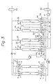
- Figure 3 is a flowsheet of the continuous adsorptive process of separating and concentrating carbon monoxide after removing carbon dioxide and nitrogen from converter off-gases.
- Adsorption columns A and B are packed with an adsorbent selective for carbon dioxide. The two columns are evacuated to 100 Torr (13.3 kPa), preferably to 60 Torr (8 kPa), with a vacuum pump. Then, the feed gas is introduced into column A through a valve 1, with the other valves in the system left closed.
- column B is maintained in at under-pressure, that is, in vacuum.
- column A is pressurized, and is maintained at 0.01-3.0 kg/cm2 ⁇ G (101-400 kPa), preferably 0.2-1.0 kg/cm2 ⁇ G (120-200 kPa).
- Valve 2 is opened, and CO2 and part of CO are adsorbed on or in the adsorbent and the remainder of the feed gas.
- valves 1 and 2 are closed.
- valve 3 is open, and pressure of column A is decreased to near one atmospheric pressure.
- Valve 3 is closed and valve 4 is open, so column A is evacuated by vacuum pump, blower or ejector to, preferably 100 Torr (13.3 kPa) and more preferably, 30 Torr (4 kPa) in order to desorb carbon dioxide.
- Valve 5 is open (at this time, amount of gas for purge is adjusted by hand valve 14), whereby CO2 remaining on or in the adsorbent is purged by passing through the waste gas of the second adsorption stage. Then the pressure of column A is 270 Torr. Then valves 4 and 5 are closed, and valve 6 is open, so column A is pressurized by introducing the product gas thereto. The flow between or among said columns is switched.
- Adsorption columns C, D, E and F contain an adsorbent exhibiting selective adsorbing property to carbon monoxide.
- Adsorption columns C, D, E and F are evacuated to 100 Torr (1.33 kPa), preferably 30 Torr (4 kPa) by means of vacuum pump 41.
- Valve 16 is open.
- the first stage product gas is introduced into adsorption column C.
- the rate of increase in pressure of column C is adjusted by valve 15.
- valves 17 and 18 are open and at the same time, valve 16 is closed.
- Introduction of the first stage product gas is continued.
- Carbon monoxide is adsorbed on or in the adsorbent and more poorly adsorbable component, i.e. nitrogen is passed through column C.
- Some of the component passing through column C is used as a gas for purge in the first adsorption stage.
- the remainder of the component can be used as fuel, because it contains considerable amount of CO.
- the remainder of the component is stored in tank 43.
- Adsorption step is continued by passing definite amount of the first stage product gas through column C for a given time. Valves 17 and 18 are closed and valve 19 is open. Pressure of column C is reduced to one atmospheric pressure and the gas withdrawn from column C is introduced into column D. Then valve 20 is open and part of the second stage product gas is introduced from product tank 42 for purging the gas remaining in the portion between the absorbent particles. The gas withdrawn in the purging step is utilized for pressurizing the other column.
- column C is evacuated by vacuum pump to desorb carbon monoxide from the adsorbent.
- the pressure of column C is reduced to less than 300 Torr (40 kPa), preferably 300-30 Torr (40-4 kPa).
- the flow between or among said columns is switched so as to repeat the above steps in the columns.
- Tank for waste gas is shown at 43.
- Carbon monoxide can be separated from a mixture comprising CO, CO2 and more poorly adsorbable component, N2 by combining the first adsorption stage and the second adsorption stage.
- the waste gas of the second adsorption stage can be used as a gas for purge of the first adsorption stage.
- the product gas, CO separated according to the present invention contains CO2 of less than 0.5% and N2 of less than 1%.
- the embodiments shown in Figures 4 and 5 relate to separation of CO from the first stage product gas and another feed gas comprising carbon monoxide and more poorly adsorbable component, such as nitrogen.
- the embodiment shown in Figure 4 is explained in the following.
- Adsorption columns A and B contain adsorbent exhibiting selective adsorbing property to carbon monoxide.
- Columns A and B are evaporated to 30 Torr, preferably 60 Torr by means of vacuum pump 111.
- Valve 101 is open and valves 102-110 are closed.
- Column A is pressurized by introducing feed gas thereinto.
- Column B is still maintained at a pressure close to vacuum.
- Valve 103 is open.
- Introduction of feed gas into column A is continued at a pressure of 0.1-3.0 kg/cm2 ⁇ G (110-400 kPa), preferably 0.2-1.0 kg/cm2 ⁇ G (120-200 kPa). Then valve 101 is closed.
- Valve 103 is open and part of the gas remaining in proportion around exit of column A is discharged to 0.1-0.75 kg/cm2 ⁇ G (110-175 kPa) outside all of the columns. Then valve 103 is open and valve 105 is closed to connect column A to column B. The gas discharged from column A is introduced to column B until pressure of column is reduced to near one atmospheric pressure. The valve 105 is closed and valve 107 is open, so part of the product gas is passed through column A from tank 112 for product gas to purge poorly adsorbable component, N2 remaining in column A. CO concentration of gas withdrawn in the purging step is higher than that in feed gas. So, the gas withdrawn in the purging step can be utilized for pressurizing the other column.
- valve 107 is closed and valve 109 is open, so column A is evacuated by means of vacuum pump to recover product gas, CO from the adsorbent of column A.
- pressure of column A is reduced to less than 300 Torr (40 kPa), preferably 300-30 Torr (40-4 kPa).
- Tank for waste gas is shown at 113.
- PSA consisting of adsorption, depressurization, evacuation, purge, and pressurization by product, pressurization by feed gas was used in the first adsorption stage.
- PSA consisting of pressurization by first stage product gas, adsorption, depressurization, purge, evacuation and pressurization by gas withdrawn from the other column was used in the second adsorption stage.
- the product gas had the following components: CO 98.6% CO2 0.5% N2 0.9% H2 0 O2 0
- Example 1 The procedure of Example 1 was repeated except that the following off-gas from convert furnace was used and the following conditions were used.
- Off-gas CO 86% CO2 4% N2 4% H2 6% Operation temperature 25°C
- Adsorbent ZE-501 Line speed of off-gas 6.5 cm/sec.
- Adsorption pressure 1.1 kg/cm2 ⁇ G (110 kPa)
- Amount of CO recovered 25.7 m3 Yield of CO was 68.6%.
- Feed gas had the following components: CO 85.3% N2 5.7% CO2 0.15% H2 8.55%
- Adsorption cycle was in the following:
- Example 3 The procedure of Example 3 was repeated except that pressurization (7) by gas discharged is depressurization (4) was not used. Amount of feed gas fed was 50.5 NM3 and amount of CO recovered was 10.8 NM3. Yield was 25.09%. Purity of CO was 99.9%.
- Time sequence of the best process of this invention is as follows: TABLE 1 First stage Cycle time (second) Column A Column B 0-15 adsorption depressurization 15-60 " evacuation 60-100 " purge by waste gas of second stage 100-120 “ pressurization by product gas TABLE 2 Second stage Cycle time (second) Column A Column B 0-60 evacuation pressurization by first stage product gas (1.0 kg/cm2 ⁇ G) 200 kPa 60-120 evacuation (80 Torr (10.6 kPa) adsorption (1.0 kg/cm2 ⁇ G) 200 kPa 120-180 pressurization by gas withdrawn from the other column (380 Torr 50 kPa)) depressurization (760 Torr 96 kPa) 180-240 pressurization by purge gas purge (0 kg/cm2 ⁇ G) 100 kPa 240-300 pressurization by first stage product gas (1.0 kg/cm2 ⁇ G) 200 kPa evacuation 300-360 adsorption (1.0 kg/cm2 ⁇ G
- Table 3 shows the step cycle by using four adsorption columns according to this invention.
- adsorption column A adsorption column B adsorption column C adsorption column D 1 evacuation pressurization by feed gas depressurization pressurization by gas withdrawn from the other column 2 evacuation adsorption purge by product gas pressurization by purge gas 3 pressurization by gas withdrawn from the other column depressurization evacuation pressurization by feed gas 4 pressurization by purge gas purge by product gas evacuation adsorption 5 pressurization by feed gas evacuation pressurization by gas withdrawn from the other column depressurization 6 adsorption evacuation pressurization by purge gas purge by product gas 7 depressurization pressurization by gas withdrawn from the other column pressurization by feed gas evacuation 8 purge by feed gas pressurization by purge gas adsorption evacuation
- Example 1 The procedure of Example 1 was repeated under the following experimental conditions: feed gas CO 21% CO2 8% CH4 3% H2 67% Temperature 25°C Line speed of feed gas 8.5 cm/sec. Adsorption pressure 2.0 kg/cm2 ⁇ G Degree of evacuation 80 Torr (10 kPa) (first stage) 30 Torr (4 kPa) (second stage) Amount of feed gas fed 103 NM3 Amount of CO recovered 12.6 NM3 Product Gas: CO 99% CH4 0.15% H2 0.05% CO2 0.02% Yield 58%
Landscapes
- Chemical & Material Sciences (AREA)
- Organic Chemistry (AREA)
- Engineering & Computer Science (AREA)
- General Chemical & Material Sciences (AREA)
- Oil, Petroleum & Natural Gas (AREA)
- Chemical Kinetics & Catalysis (AREA)
- Combustion & Propulsion (AREA)
- Analytical Chemistry (AREA)
- Inorganic Chemistry (AREA)
- Separation Of Gases By Adsorption (AREA)
- Carbon And Carbon Compounds (AREA)
Description
- The present invention relates to a method for obtaining high-purity carbon monoxide from a feed gas, such as off-gases from converters furnace or blast furnaces, containing carbon dioxide and nitrogen in addition to carbon monoxide by a modification of the pressure swing adsorption (PSA) technique.
- Off-gases from refining vessels used in iron mills contain fairly large amounts of carbon monoxide. The chemical composition of off-gases from a converter and a blast furnace are listed below.
CO CO₂ N₂ H₂ Off-gas from converter furnace 60-87% 3-20% 3-20% 1-10% Off-gas from blast furnace 20-30% 20-30% 40-60% 1-10% - High-purity CO recovered from these off-gases at low cost could be used as a raw material for synthesis of chemicals or as a gas to be blown into molten metal in refining vessels. Most reactions for the synthesis of chemicals require high temperatures and pressures, and therefore, the CO used should have the lowest possible content of CO₂ that corrodes the reactor by oxidation. In order to ensure a high reaction efficiency, N₂ that usually does not take part in the reaction should be removed as much as possible. While various gases are blown into a refining vessel for the purpose of increasing the efficiency of metal refining; argon that is expensive is typically used in order to avoid the increase in the concentrations of impure gases (e.g. H₂ and N₂) in the molten metal. Since off-gases are produced in large quantities from converters and blast furnaces in an iron mill, high-purity CO recovered from these gases at low cost could be used as an almost equally effective alternative to argon. In this case, the nitrogen content of the high-purity CO should be as low as possible for the purpose of preventing the increase in the N₂ content of molten iron. Furthermore, the CO₂ concentration should desirably be low in order to prevent oxidative attack of the carbon-base refractory lining of refining vessel.
- It has been proposed to recover high-purity CO from off-gases from iron mills either by deep-freezing separation or by solution absorption techniques such as the copper solution method and cosorb method. However, the deep-freezing separation technique requires low temperature and high pressure, whereas the solution absorption technique requires high temperature and pressure. Furthermore, both techniques need complicated and expensive equipment. Another disadvantage with the deep-freezing technique is that the boiling points of N₂ and CO are so close to each other that their complete separation is very difficult.
- Therefore, the present inventors looked to adsorption techniques for recovering high-purity CO by a simpler and less expensive process. The objective of the inventors was to recover high-purity CO not only from off-gases from refining furnaces but also from off-gases from petroleum refineries and chemical synthesis plants, as well as from off-gases resulting from the partial oxidation or hydroreforming of natural gas and heavy hydrocarbon oils.
- Separation of gases by pressure-swing adsorption is known, and methods for recovery of less strongly adsorbable gases (those components which are not easily adsorbed on an adsorbent) are shown in Japanese Patent Publication Nos. 23928/63 and 15045/63. However, as far as the inventors know, nobody has succeeded in recovery of high-purity CO from off-gases containing not only nitrogen but also carbon dioxide which has a high tendency to be absorbed together with carbon monoxide.
- U.S. Serial No. 517,272 by Matsui et al filed on July 26, 1983 (US-A-4.468.238) which was assigned to the assignee of this invention discloses removal of nitrogen from mixture comprising nitrogen and carbon monoxide or nitrogen, carbon monoxide and carbon dioxide. However, Matsui et al does not disclose separation of carbon dioxide from said mixture.
- EP-A-0 008 512 discloses a pressure swing adsorption process for recovering hydrogen and carbon dioxide from a mixture of H₂, CO₂ and CO. When present, N₂ contained in said mixture is recovered as part of a so-called "secondary component" in admixture with CO.
- An object of this invention is to provide a process for separating CO from a mixture comprising at least CO₂, CO and N₂ through PSA process.
- Another object of this invention is to provide a process for separating CO from a mixture comprising at least CO₂, CO and N₂ in which Matsui et al process is improved.
- Still another object of this invention is to provide a process for separating CO from a mixture comprising at least CO₂, CO and N₂ in which adsorption step is carried out at a near atmospheric pressure for saving energy for pressurizing adsorption columns.
- According to the invention there is provided a process for separating carbon monoxide from a feed gas comprising CO₂, CO and N₂ by PSA in a two stage adsorption operation which comprises a first adsorption stage for removing CO₂ from said feed gas and a second adsorption stage for separating CO from gaseous mixture withdrawn as first stage product gas from the first adsorption stage:
- (1) the first adsorption stage comprising pressure swing adsorption with repeated adsorption and desorption using at least two adsorption columns containing an adsorbent exhibiting selective adsorption properties for carbon dioxide to remove carbon dioxide from said feed gas, and
- (2) the second adsorption stage comprising a process for separating carbon monoxide from the gaseous mixture, which has been withdrawn from the first adsorption stage, through PSA using at least two adsorption columns containing an adsorbent exhibiting selective adsorption properties for carbon monoxide, characterised in that the second adsorption stage comprises:
- (i) pressurizing an adsorption column by gaseous mixture which has been withdrawn from the first adsorption stage;
- (ii) continuing the introduction of the gas mixture referred to in step (i) into the adsorption column pressurised in step (i) so as to adsorb carbon monoxide on or in the adsorbent until the concentration of the CO in the gas leaving the adsorption column becomes equal to the concentration of the CO in the gas entering the adsorption column or until just before the time when the two concentrations become equal;
- (iii) connecting the adsorption column in which step (ii) has been completed to another adsorption column in which step (v) was previously completed, to reduce the pressure in the former adsorption column to atmospheric pressure;
- (iv) purging N₂ by cocurrently introducing product gas into the first-mentioned adsorption column of step (iii), and in which step (iii) has been completed
- (v) evacuating the adsorption column in which step (iv) has been completed to recover carbon monoxide adsorbed on or in the adsorbent of the adsorption column; and
- (vi) connecting the adsorption column which step (v) has been completed, to an adsorption column, in which step (ii) was previously completed to increase pressure in said adsorption column referred to in step (v),
- (vii) after step (vi) is completed, pressurising the first of the two columns mentioned in step (vi) by gas withdrawn in the purging step of another column,
- After step (ii) is completed and before step (iii) is started, part of the gaseous mixture remaining in the column may be removed outside all the adsorption columns.
- Preferably said first adsorption stage comprises:
- (i) pressurizing an adsorption column by the product gas of the first adsorption stage,
- (ii) introducing said feed gas into the adsorption column, pressurized in step (i), so as to adsorb carbon dioxide as a main component on or in the adsorbent,
- (iii) depressurizing the adsorption column in which step (ii) has been completed to near one atmospheric pressure,
- (iv) evacuating the column in which step (iii) has been completed, and
- (v) purging carbon dioxide by introducing waste gas obtained in the adsorbing step of the second stage, into the column in which step (iv) was previously completed,
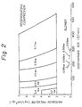
- Figure 1 is a graph showing relationship between adsorption pressure and adsorbed CO;
- Figure 2 is a graph showing comparison of energy in case of using reciprocating compressor with that in case of using blower; and
- Figures 3 and 4 are flowsheets showing preferable apparatuses of this invention.
- The adsorbents employed in the practice of the first and second adsorption stages of this invention include natural or synthetic zeolites, molecular sieves, activated carbon and the like. Mordenite type zeolite and adsorbent obtained by grinding mordenite type zeolite, followed by sintering the reformed zeolite with a binding agent are preferable.
- In the first adsorption stage, carbon dioxide is removed from a mixture comprising CO, CO₂ and more poorly adsorbable component than CO, such as nitrogen through PSA.
- The preferable first adsorption stage comprises in the following:
- At least two adsorption columns containing an adsorbent exhibiting selective absorb property to carbon dioxide are used. The process comprises:
- (i) a step of pressurizing the adsorption column, in which step (v) was previously completed, to a pressure of 0.2-3.0 kg/cm² · G (120-400 kPa) by introducing the first stage product gas into the column countercurrently;
- (ii) a step of introducing the feed gas into the adsorption column, in which step (i) was previously completed, so as to adsorb carbon dioxide on or in the adsorbent;
- (iii) a step of depressurizing the adsorption column, in which step (ii) was previously completed, to near atmospheric pressure countercurrently;
- (iv) a step of evacuating the adsorption column, in which step (iii) was previously completed by means of vacuum pump blower or ejector, and preferably the column is evaporated to 30-300 (4-40 kPa) Torr; and
- (v) a step of purging carbon dioxide by countercurrently passing the waste gas of the second adsorption stage through the adsorption column, in which step (iv) was previously completed;
- Steps of the second adsorption stage are explained in detail in the following:
- In this step, the first stage product gas is introduced into an adsorption column to increase pressure in the columns. Since gas to be recovered according to this invention is easily adsorbable component, too high adsorption pressure is unnecessary. In general, the adsorption pressure of as low as 3 kg/cm² · G (400 kPa) is sufficient. The adsorption pressure of less than 1 kg/cm² · G (200 kPa), for example 0.1 kg/cm² · G (110 kPa) can also be used. However, adsorption pressure of more than 3 kg/cm² · G (400 kPa) may be used.
- Adsorption step is continued until the concentration of the easily adsorbable component, for example CO, in the gas leaving the adsorption column becomes equal to the concentration of the same component entering the adsorption column, or until just before the time when the two concentrations become equal.
- When step (ii) is completed, the concentration of the poorly adsorbable component is relatively high around the exit of the column.
- So, part of the gaseous mixture remaining in the column may be removed outside all the adsorption columns in order to enhance purity of the product gas. It is preferable that the gaseous mixture remaining in the column may be removed to a pressure of three fourth-one fifth of adsorption pressure. This step is optional.
- The adsorption column, in which step (iii) was previously completed, is connected to the other adsorption column, in which step (vi) is previously completed to withdraw the gas component from the former column and introduce it into the latter column, thereby reducing the pressure in the former adsorption column to one atmosphere or a pressure close to it. The pressure in the former adsorption column may be reduced to near pressure equalization of the two columns.
- Product gas is passed through the adsorption column, in which step (iv) was previously completed, to purge nitrogen between the adsorbent particles. It is preferable that the pressure in this step is lower than the adsorption pressure and is higher than one atmosphere. In general, it may be unnecessary to use pump; and the step may be carried out by connecting the adsorption column to storage tank for product gas. The product gas is cocurrently passed through the column.
- The adsorption column, in which step (v) was previously completed, is evacuated to a pressure below one atmospheric pressure by means of vacuum pump, blower ejector in order to recover product gas, CO. It is preferable that the column is evacuated to a pressure less than 300 Torr (40 kPa), more preferable to 30-100 Torr (4-13.3 kPa).
- The adsorption column, in which step (vi) was previously completed, is connected to the other adsorption column, in which step (ii) was previously completed, to pressurize the former column by introducing gas from the latter column to the former column. Preferably, introduction of the gas is cocurrently carried out. This step is continued until the pressure in the latter column is reduced to one atmosphere or a pressure close to it. In end of this step, the pressure in the former column is less than one atmosphere. The pressure in the former adsorption column may be increased to near pressure equalization of the two columns.
- The gas withdrawn in step (v) of the other adsorption column is introduced into the adsorption column, in which step (vii) was previously completed.
- According to one aspect of the present invention, adsorption is carried out at nearly atmospheric pressure. The present invention generally relates to a method of separating carbon monoxide in a feed gas containing nitrogen as well as carbon monoxide, using at least two adsorption columns packed with an adsorbent selective for carbon monoxide such as activated carbon, synthetic or natural zeolite or a mixture thereof.
- The present invention is explained by typical embodiment, but not limit the scope of this invention.
- Figure 3 is a flowsheet of the continuous adsorptive process of separating and concentrating carbon monoxide after removing carbon dioxide and nitrogen from converter off-gases. Adsorption columns A and B are packed with an adsorbent selective for carbon dioxide. The two columns are evacuated to 100 Torr (13.3 kPa), preferably to 60 Torr (8 kPa), with a vacuum pump. Then, the feed gas is introduced into column A through a valve 1, with the other valves in the system left closed.
- At this time, column B is maintained in at under-pressure, that is, in vacuum. After column A is pressurized, and is maintained at 0.01-3.0 kg/cm² · G (101-400 kPa), preferably 0.2-1.0 kg/cm² · G (120-200 kPa).
Valve 2 is opened, and CO₂ and part of CO are adsorbed on or in the adsorbent and the remainder of the feed gas. After a definite amount of the feed gas is passed through column A for a given time,valves 1 and 2 are closed. Then,valve 3 is open, and pressure of column A is decreased to near one atmospheric pressure.Valve 3 is closed and valve 4 is open, so column A is evacuated by vacuum pump, blower or ejector to, preferably 100 Torr (13.3 kPa) and more preferably, 30 Torr (4 kPa) in order to desorb carbon dioxide.Valve 5 is open (at this time, amount of gas for purge is adjusted by hand valve 14), whereby CO₂ remaining on or in the adsorbent is purged by passing through the waste gas of the second adsorption stage. Then the pressure of column A is 270 Torr. Thenvalves 4 and 5 are closed, andvalve 6 is open, so column A is pressurized by introducing the product gas thereto. The flow between or among said columns is switched. - In the second adsorption stage, CO is separated from the first stage product gas. Adsorption columns C, D, E and F contain an adsorbent exhibiting selective adsorbing property to carbon monoxide.
- Adsorption columns C, D, E and F are evacuated to 100 Torr (1.33 kPa), preferably 30 Torr (4 kPa) by means of
vacuum pump 41. Valve 16 is open. The first stage product gas is introduced into adsorption column C. The rate of increase in pressure of column C is adjusted byvalve 15. In the adsorption step,valves tank 43. - Adsorption step is continued by passing definite amount of the first stage product gas through column C for a given time.
Valves valve 19 is open. Pressure of column C is reduced to one atmospheric pressure and the gas withdrawn from column C is introduced into column D. Thenvalve 20 is open and part of the second stage product gas is introduced fromproduct tank 42 for purging the gas remaining in the portion between the absorbent particles. The gas withdrawn in the purging step is utilized for pressurizing the other column. - Then
valves valve 21 is open. So, column C is evacuated by vacuum pump to desorb carbon monoxide from the adsorbent. The pressure of column C is reduced to less than 300 Torr (40 kPa), preferably 300-30 Torr (40-4 kPa). The flow between or among said columns is switched so as to repeat the above steps in the columns. Tank for waste gas is shown at 43. - Carbon monoxide can be separated from a mixture comprising CO, CO₂ and more poorly adsorbable component, N₂ by combining the first adsorption stage and the second adsorption stage. Particularly, the waste gas of the second adsorption stage can be used as a gas for purge of the first adsorption stage. The product gas, CO separated according to the present invention contains CO₂ of less than 0.5% and N₂ of less than 1%.
- The embodiments shown in Figures 4 and 5 relate to separation of CO from the first stage product gas and another feed gas comprising carbon monoxide and more poorly adsorbable component, such as nitrogen. The embodiment shown in Figure 4 is explained in the following.
- Adsorption columns A and B contain adsorbent exhibiting selective adsorbing property to carbon monoxide. Columns A and B are evaporated to 30 Torr, preferably 60 Torr by means of
vacuum pump 111.Valve 101 is open and valves 102-110 are closed. Column A is pressurized by introducing feed gas thereinto. Column B is still maintained at a pressure close to vacuum.Valve 103 is open. Introduction of feed gas into column A is continued at a pressure of 0.1-3.0 kg/cm² · G (110-400 kPa), preferably 0.2-1.0 kg/cm² · G (120-200 kPa). Thenvalve 101 is closed.Valve 103 is open and part of the gas remaining in proportion around exit of column A is discharged to 0.1-0.75 kg/cm² · G (110-175 kPa) outside all of the columns. Thenvalve 103 is open andvalve 105 is closed to connect column A to column B. The gas discharged from column A is introduced to column B until pressure of column is reduced to near one atmospheric pressure. Thevalve 105 is closed andvalve 107 is open, so part of the product gas is passed through column A fromtank 112 for product gas to purge poorly adsorbable component, N₂ remaining in column A. CO concentration of gas withdrawn in the purging step is higher than that in feed gas. So, the gas withdrawn in the purging step can be utilized for pressurizing the other column. - Then
valve 107 is closed andvalve 109 is open, so column A is evacuated by means of vacuum pump to recover product gas, CO from the adsorbent of column A. In general, pressure of column A is reduced to less than 300 Torr (40 kPa), preferably 300-30 Torr (40-4 kPa). - The flow between or among the columns is switched. Tank for waste gas is shown at 113.
- This invention is further illustrated by the following examples, but not limit the scope.
- In this example, off-gas from converter furnace having the following components was used.
CO 83% CO₂ 2.7% N₂ 4.9% H₂ 9.3% O₂ 0.1% - PSA consisting of adsorption, depressurization, evacuation, purge, and pressurization by product, pressurization by feed gas was used in the first adsorption stage. PSA consisting of pressurization by first stage product gas, adsorption, depressurization, purge, evacuation and pressurization by gas withdrawn from the other column was used in the second adsorption stage.
- In the first stage, steel columns (12⁸ × 1.7 m) containing Zeoharb (available by Osaka Sanso Kogyo Ltd.) (50 kg 1/8 inch pellet) were used. In the second stage, steel columns (16⁸ × 2.4 m) containing activated Zeoharb (166 kg 1/8 inch pellet) were used. All columns were evacuated to 100 Torr (13 kPa) in the first stage and all columns were evacuated to 60 Torr (8 kPa) in the second stage.
- Said off-gas was fed into first stage columns at line speed of 6 cm/sec. 32.8 Cubic meter of said off-gas was used. 19.3 Cubic meter of product gas, carbon monoxide was obtained. Amount of waste gas was 13.5 cubic meter. Yield of CO was 68%.
- The product gas had the following components:
CO 98.6% CO₂ 0.5% N₂ 0.9% H₂ 0 O₂ 0 - The procedure of Example 1 was repeated except that the following off-gas from convert furnace was used and the following conditions were used.
Off-gas CO 86% CO₂ 4% N₂ 4 % H₂ 6 % Operation temperature 25°C Adsorbent ZE-501 Line speed of off-gas 6.5 cm/sec. Adsorption pressure 1.1 kg/cm² · G (110 kPa) Amount of off-gas fed 42.9 m³ Amount of CO recovered 25.7 m³ Yield of CO was 68.6%. - The product, CO had the following components:
CO 98.7% CO₂ 0.5% N₂ 0.8% - In this example, only second adsorption stage was conducted. Feed gas had the following components:
CO 85.3% N₂ 5.7% CO₂ 0.15% H₂ 8.55% - Adsorption cycle was in the following:
- 1. Pressurization by feed gas-adsorption-adsorption-depressurization (gas discharged from column is not utilized in other column)-depressurization (gas discharged in column is utilized in other column)-purge-evacuation-pressurization.
- 1. Pressurization by feed gas
- 2. Adsorption
- 3. Depressurization (gas discharged from column is not utilized in other column)
- 4. Depressurization (gas discharged from column is utilized in other column)
- 5. Purge
- 6. Evacuation
- 7. Pressurization by gas discharged by gas in 4 depressurization.
- 8. Pressurization by purge gas
- The procedure of Example 3 was repeated except that pressurization (7) by gas discharged is depressurization (4) was not used. Amount of feed gas fed was 50.5 NM³ and amount of CO recovered was 10.8 NM³. Yield was 25.09%. Purity of CO was 99.9%.
- Time sequence of the best process of this invention is as follows:
TABLE 1 First stage Cycle time (second) Column A Column B 0-15 adsorption depressurization 15-60 " evacuation 60-100 " purge by waste gas of second stage 100-120 " pressurization by product gas TABLE 2 Second stage Cycle time (second) Column A Column B 0-60 evacuation pressurization by first stage product gas (1.0 kg/cm² · G) 200 kPa 60-120 evacuation (80 Torr (10.6 kPa) adsorption (1.0 kg/cm² · G) 200 kPa 120-180 pressurization by gas withdrawn from the other column (380 Torr 50 kPa)) depressurization (760 Torr 96 kPa) 180-240 pressurization by purge gas purge (0 kg/cm² · G) 100 kPa 240-300 pressurization by first stage product gas (1.0 kg/cm² · G) 200 kPa evacuation 300-360 adsorption (1.0 kg/cm² · G) 200 kPa evacuation (80 Torr 10.6 kPa) 360-420 depressurization (760 Torr 96 kPa) pressurization by gas withdrawn from other column (360 Torr 48 kPa) 420-480 purge (0 kg/cm² · G) 100 kPa pressurization by purge gas (730 Torr (97 kPa)) - The following Table 3 shows the step cycle by using four adsorption columns according to this invention.
TABLE 3 adsorption column A adsorption column B adsorption column C adsorption column D 1 evacuation pressurization by feed gas depressurization pressurization by gas withdrawn from the other column 2 evacuation adsorption purge by product gas pressurization by purge gas 3 pressurization by gas withdrawn from the other column depressurization evacuation pressurization by feed gas 4 pressurization by purge gas purge by product gas evacuation adsorption 5 pressurization by feed gas evacuation pressurization by gas withdrawn from the other column depressurization 6 adsorption evacuation pressurization by purge gas purge by product gas 7 depressurization pressurization by gas withdrawn from the other column pressurization by feed gas evacuation 8 purge by feed gas pressurization by purge gas adsorption evacuation - The procedure of Example 1 was repeated under the following experimental conditions:
feed gas CO 21% CO₂ 8 % CH₄ 3% H₂ 67 % Temperature 25°C Line speed of feed gas 8.5 cm/sec. Adsorption pressure 2.0 kg/cm² · G Degree of evacuation 80 Torr (10 kPa) (first stage) 30 Torr (4 kPa) (second stage) Amount of feed gas fed 103 NM³ Amount of CO recovered 12.6 NM³ Product Gas: CO 99% CH₄ 0.15% H₂ 0.05% CO₂ 0.02% Yield 58%
Claims (5)
- A process for separating carbon monoxide from a feed gas comprising CO₂, CO and N₂ by PSA in a two stage adsorption operation which comprises a first adsorption stage for removing CO₂ from said feed gas and a second adsorption stage for separating CO from gaseous mixture withdrawn as first stage product gas from the first adsorption stage:(1) the first adsorption stage comprising pressure swing adsorption with repeated adsorption and desorption using at least two adsorption columns containing an adsorbent exhibiting selective adsorption properties for carbon dioxide to remove carbon dioxide from said feed gas, and(2) the second adsorption stage comprising a process for separating carbon monoxide from the gaseous mixture, which has been withdrawn from the first adsorption stage, through PSA using at least two adsorption columns containing an adsorbent exhibiting selective adsorption properties for carbon monoxide, characterised in that the second adsorption stage comprises:(i) pressurising an adsorption column by gaseous mixture which has been withdrawn from the first adsorption stage;(ii) continuing the introduction of the gas mixture referred to in step (i) into the adsorption column pressurised in step (i) so as to adsorb carbon monoxide on or in the adsorbent until the concentration of the CO in the gas leaving the adsorption column becomes equal to the concentration of the CO in the gas entering the adsorption column or until just before the time when the two concentrations became equal;(iii) connecting the adsorption column in which step (ii) has been completed to another adsorption column in which step (v) was previously completed, to reduce the pressure in the former adsorption column to atmospheric pressure;(iv) purging N₂ by cocurrently introducing product gas into the first-mentioned adsorption column of step (iii), and in which step (iii) has been completed;(v) evacuating the adsorption column in which step (iv) has been completed to recover carbon monoxide adsorbed on or in the adsorbent of the adsorption column;(vi) connecting the adsorption column in which step (v) has been completed to another adsorption column, in which step (ii) was previously completed to increase pressure in said adsorption column referred to in step (v), and(vii) after step (vi) is completed, pressurising the first of the two columns mentioned in step (vi) by gas withdrawn in the purging step of another column,periodically switching the flow between or among said adsorption columns so as to repeat the above steps in the columns.
- The process as defined in Claim 1, wherein said first adsorption stage comprises:(i) pressurizing an adsorption column by the product gas of the first adsorption stage(ii) introducing said feed gas into the adsorption column, pressurized in step (i), so as to adsorb carbon dioxide as a main component on or in the adsorbent,(iii) depressurizing the adsorption column in which step (ii) has been completed to near one atmospheric pressure,(iv) evacuating the column in which step (iii) has been completed, and(v) purging carbon dioxide by introducing waste gas obtained in the absorbing step of the second stage, into the column in which step (iv) was previously completed,periodically switching the flow between or among said columns so as to repeat the above steps in the columns.
- The process as defined in Claim 1 or Claim 2 wherein after step (ii) of the second stage is completed and before step (iii) of the second stage is started, the second stage further contains a step of depressuring the column, thereby discharging part of the gas remaining in the column outside all the columns.
- The process according to Claim 1 wherein step (iii) is countercurrently carried out.
- The process according to Claim 1 wherein the evacuation is countercurrently carried out.
Applications Claiming Priority (6)
| Application Number | Priority Date | Filing Date | Title |
|---|---|---|---|
| JP110616/83 | 1983-06-20 | ||
| JP58110616A JPS605012A (en) | 1983-06-20 | 1983-06-20 | Purification of carbon monoxide from mixed gas containing carbon monoxide by using adsorption |
| JP187479/83 | 1983-10-06 | ||
| JP58187479A JPS6078612A (en) | 1983-10-06 | 1983-10-06 | Concentration of carbon monoxide in gaseous mixture containing carbon monoxide by using adsorbing method |
| JP58188117A JPS6078615A (en) | 1983-10-07 | 1983-10-07 | Purification of carbon monoxide in gaseous mixture containing at least carbon monoxide by using adsorbing method |
| JP188117/83 | 1983-10-07 |
Publications (4)
| Publication Number | Publication Date |
|---|---|
| EP0129444A2 EP0129444A2 (en) | 1984-12-27 |
| EP0129444A3 EP0129444A3 (en) | 1987-06-24 |
| EP0129444B1 EP0129444B1 (en) | 1990-11-28 |
| EP0129444B2 true EP0129444B2 (en) | 1995-04-19 |
Family
ID=27311775
Family Applications (1)
| Application Number | Title | Priority Date | Filing Date |
|---|---|---|---|
| EP84304148A Expired - Lifetime EP0129444B2 (en) | 1983-06-20 | 1984-06-19 | Methods for obtaining high-purity carbon monoxide |
Country Status (5)
| Country | Link |
|---|---|
| US (1) | USRE32590E (en) |
| EP (1) | EP0129444B2 (en) |
| KR (1) | KR900001537B1 (en) |
| CA (1) | CA1238868A (en) |
| DE (1) | DE3483664D1 (en) |
Families Citing this family (18)
| Publication number | Priority date | Publication date | Assignee | Title |
|---|---|---|---|---|
| US4705541A (en) * | 1987-02-12 | 1987-11-10 | Air Products And Chemicals, Inc. | Production of mixed gases of controlled composition by pressure swing adsorption |
| FR2624759B1 (en) * | 1987-12-22 | 1990-05-04 | Air Liquide | PROCESS FOR TREATING A GAS MIXTURE BY ADSORPTION |
| US5002591A (en) * | 1988-10-14 | 1991-03-26 | Vbm Corporation | High efficiency PSA gas concentrator |
| JPH02129014A (en) * | 1988-11-04 | 1990-05-17 | Mitsui Eng & Shipbuild Co Ltd | Production of carbon monoxide gas |
| US4914218A (en) * | 1989-02-17 | 1990-04-03 | Ravi Kumar | Adsorptive process for separating multicomponent gas mixtures |
| US4913709A (en) * | 1989-02-17 | 1990-04-03 | Ravi Kumar | Adsorption process for recovering two high purity gas products from multicomponent gas mixtures |
| US4915711A (en) | 1989-05-18 | 1990-04-10 | Air Products And Chemicals, Inc. | Adsorptive process for producing two gas streams from a gas mixture |
| US5293449A (en) * | 1990-11-23 | 1994-03-08 | Comsat Corporation | Analysis-by-synthesis 2,4 kbps linear predictive speech codec |
| US5531809A (en) * | 1994-09-14 | 1996-07-02 | Air Products And Chemicals, Inc. | Pretreatment layer for CO-VSA |
| US6045603A (en) | 1998-08-21 | 2000-04-04 | The Boc Group, Inc. | Two phase pressure swing adsorption process |
| US6113672A (en) | 1999-01-21 | 2000-09-05 | The Boc Group, Inc. | Multiple equalization pressure swing adsorption process |
| US6083299A (en) | 1999-01-21 | 2000-07-04 | The Boc Group, Inc. | High pressure purge pressure swing adsorption process |
| CN100340324C (en) * | 2004-06-11 | 2007-10-03 | 成都天立化工科技有限公司 | Two-section totally recovering pressure swing adsorption gas separating method |
| DK2989233T3 (en) * | 2013-03-26 | 2020-10-12 | Haldor Topsoe As | Process for the production of carbon monoxide (CO) from carbon dioxide (CO2) in a solid oxide electrolysis cell |
| EP2832421B1 (en) | 2013-07-30 | 2016-05-25 | Haldor Topsøe A/S | Process for producing high purity co by membrane purification of soec-produced co |
| KR101986632B1 (en) * | 2017-08-10 | 2019-06-07 | 울산과학기술원 | Blast furnace top gas recycle system |
| CN108977234B (en) * | 2018-07-25 | 2020-08-04 | 戴乐亭 | Decarburization method for coke oven gas and converter and/or blast furnace gas |
| KR102059068B1 (en) * | 2019-04-11 | 2019-12-24 | 한국화학연구원 | Separation and recovery process of carbon monoxide from by-product gas of steel industry |
Family Cites Families (10)
| Publication number | Priority date | Publication date | Assignee | Title |
|---|---|---|---|---|
| US2944627A (en) * | 1958-02-12 | 1960-07-12 | Exxon Research Engineering Co | Method and apparatus for fractionating gaseous mixtures by adsorption |
| NL297067A (en) * | 1962-09-04 | 1900-01-01 | ||
| US3226913A (en) * | 1963-09-04 | 1966-01-04 | Union Carbide Corp | Separation process |
| US3430418A (en) * | 1967-08-09 | 1969-03-04 | Union Carbide Corp | Selective adsorption process |
| BE792039A (en) * | 1971-11-30 | 1973-05-29 | Air Liquide | PROCESS AND PLANT FOR FRACTIONING A GAS MIXTURE BY ADSORPTION |
| DE2604305A1 (en) * | 1976-02-04 | 1977-08-11 | Linde Ag | PROCEDURE FOR SEPARATING GAS MIXTURES |
| US4171206A (en) * | 1978-08-21 | 1979-10-16 | Air Products And Chemicals, Inc. | Separation of multicomponent gas mixtures |
| US4470829A (en) * | 1981-08-31 | 1984-09-11 | Nippon Steel Corporation | Solid adsorbent for carbon monoxide and process for separation from gas mixture |
| DE3222560A1 (en) * | 1982-06-16 | 1983-12-22 | Bergwerksverband Gmbh, 4300 Essen | METHOD FOR SEPARATING AND DETERMINING RELATIVELY STRONG ON ADSORPTION AGENTS, ADSORBABLE GASES FROM GAS MIXTURES OTHERWHERE THEREOUGH ONLY LESS ADSORBABLE GASES, AND SYSTEM FOR CARRYING OUT THIS |
| JPS5922625A (en) * | 1982-07-27 | 1984-02-04 | Osaka Oxgen Ind Ltd | Method for removing gaseous nitrogen contained in gaseous carbon monoxide or gaseous mixture of carbon monoxide and carbon dioxide by adsorption method |
-
1984
- 1984-06-19 DE DE8484304148T patent/DE3483664D1/en not_active Expired - Fee Related
- 1984-06-19 CA CA000456879A patent/CA1238868A/en not_active Expired
- 1984-06-19 EP EP84304148A patent/EP0129444B2/en not_active Expired - Lifetime
- 1984-06-20 KR KR1019840003468A patent/KR900001537B1/en not_active IP Right Cessation
-
1986
- 1986-10-23 US US06/922,323 patent/USRE32590E/en not_active Expired - Lifetime
Also Published As
| Publication number | Publication date |
|---|---|
| KR850000361A (en) | 1985-02-26 |
| EP0129444B1 (en) | 1990-11-28 |
| CA1238868A (en) | 1988-07-05 |
| KR900001537B1 (en) | 1990-03-12 |
| EP0129444A2 (en) | 1984-12-27 |
| USRE32590E (en) | 1988-02-02 |
| DE3483664D1 (en) | 1991-01-10 |
| EP0129444A3 (en) | 1987-06-24 |
Similar Documents
| Publication | Publication Date | Title |
|---|---|---|
| US4539020A (en) | Methods for obtaining high-purity carbon monoxide | |
| EP0129444B2 (en) | Methods for obtaining high-purity carbon monoxide | |
| US4915711A (en) | Adsorptive process for producing two gas streams from a gas mixture | |
| EP0307843B1 (en) | Production of hydrogen and carbon monoxide | |
| US4770676A (en) | Recovery of methane from land fill gas | |
| EP0489555B1 (en) | Hydrogen and carbon monoxide production by pressure swing adsorption purification | |
| EP0008512B1 (en) | Separation of multicomponent gas mixtures | |
| US4775394A (en) | Process for separation of high purity gas from mixed gas | |
| KR880000513B1 (en) | Process for removing a nitrogen gas from mixture comprising n2 and co | |
| EP0767349B1 (en) | The use of nitrogen from an air separation plant in carbon dioxide removal from a feed gas to a further process | |
| EP0281876A1 (en) | Preparation of high purity oxygen | |
| EP0257493A1 (en) | Adsorptive separation of gas mixtures | |
| EP0385174A2 (en) | Adsorptive process for separating multicomponent gas mixtures | |
| EP0750934A2 (en) | VSA adsorption process | |
| JPH04227812A (en) | Method for recovering nitrogen gas from air | |
| EP0640376B1 (en) | Method for recovering ethylene from ethylene oxide plant vent gas | |
| EP0398339B1 (en) | Adsorptive process for producing two gas streams from a gas mixture | |
| EP0354259B1 (en) | Improved pressure swing adsorption process | |
| JPS60176901A (en) | Method for concentrating and purifying hydrogen, etc. in mixed gas containing at least hydrogen by using adsorption | |
| JP3219612B2 (en) | Method for co-producing carbon monoxide and hydrogen from mixed gas | |
| JPH0112529B2 (en) | ||
| JPS60155520A (en) | Process for purifying carbon monoxide from mixed gas containing carbon monoxide gas by adsorption process | |
| JPS60155519A (en) | Process for purifying carbon monoxide from mixed gas containing carbon monoxide using adsorption process | |
| JPS6097022A (en) | Concentration and separation of carbon monoxide in carbon monoxide-containing gaseous mixture by using adsorbing method | |
| JPS6139087B2 (en) |
Legal Events
| Date | Code | Title | Description |
|---|---|---|---|
| PUAI | Public reference made under article 153(3) epc to a published international application that has entered the european phase |
Free format text: ORIGINAL CODE: 0009012 |
|
| AK | Designated contracting states |
Designated state(s): BE DE FR GB IT SE |
|
| PUAL | Search report despatched |
Free format text: ORIGINAL CODE: 0009013 |
|
| RHK1 | Main classification (correction) |
Ipc: B01D 53/04 |
|
| AK | Designated contracting states |
Kind code of ref document: A3 Designated state(s): BE DE FR GB IT SE |
|
| 17P | Request for examination filed |
Effective date: 19871103 |
|
| RAP1 | Party data changed (applicant data changed or rights of an application transferred) |
Owner name: OSAKA SANSO KOGYO LIMITED Owner name: KAWASAKI STEEL CORPORATION |
|
| 17Q | First examination report despatched |
Effective date: 19880318 |
|
| ITF | It: translation for a ep patent filed | ||
| GRAA | (expected) grant |
Free format text: ORIGINAL CODE: 0009210 |
|
| AK | Designated contracting states |
Kind code of ref document: B1 Designated state(s): BE DE FR GB IT SE |
|
| ET | Fr: translation filed | ||
| REF | Corresponds to: |
Ref document number: 3483664 Country of ref document: DE Date of ref document: 19910110 |
|
| PLBI | Opposition filed |
Free format text: ORIGINAL CODE: 0009260 |
|
| 26 | Opposition filed |
Opponent name: LINDE AKTIENGESELLSCHAFT, WIESBADEN Effective date: 19910826 |
|
| ITTA | It: last paid annual fee | ||
| PG25 | Lapsed in a contracting state [announced via postgrant information from national office to epo] |
Ref country code: SE Free format text: LAPSE BECAUSE OF NON-PAYMENT OF DUE FEES Effective date: 19940620 |
|
| PGFP | Annual fee paid to national office [announced via postgrant information from national office to epo] |
Ref country code: BE Payment date: 19940705 Year of fee payment: 11 |
|
| EAL | Se: european patent in force in sweden |
Ref document number: 84304148.4 |
|
| PUAH | Patent maintained in amended form |
Free format text: ORIGINAL CODE: 0009272 |
|
| STAA | Information on the status of an ep patent application or granted ep patent |
Free format text: STATUS: PATENT MAINTAINED AS AMENDED |
|
| 27A | Patent maintained in amended form |
Effective date: 19950419 |
|
| AK | Designated contracting states |
Kind code of ref document: B2 Designated state(s): BE DE FR GB IT SE |
|
| PGFP | Annual fee paid to national office [announced via postgrant information from national office to epo] |
Ref country code: SE Payment date: 19950424 Year of fee payment: 12 |
|
| ET3 | Fr: translation filed ** decision concerning opposition | ||
| PG25 | Lapsed in a contracting state [announced via postgrant information from national office to epo] |
Ref country code: BE Free format text: LAPSE BECAUSE OF NON-PAYMENT OF DUE FEES Effective date: 19950630 |
|
| APAC | Appeal dossier modified |
Free format text: ORIGINAL CODE: EPIDOS NOAPO |
|
| APAC | Appeal dossier modified |
Free format text: ORIGINAL CODE: EPIDOS NOAPO |
|
| PGFP | Annual fee paid to national office [announced via postgrant information from national office to epo] |
Ref country code: GB Payment date: 19990601 Year of fee payment: 16 |
|
| PGFP | Annual fee paid to national office [announced via postgrant information from national office to epo] |
Ref country code: FR Payment date: 19990629 Year of fee payment: 16 |
|
| PGFP | Annual fee paid to national office [announced via postgrant information from national office to epo] |
Ref country code: DE Payment date: 19990813 Year of fee payment: 16 |
|
| PG25 | Lapsed in a contracting state [announced via postgrant information from national office to epo] |
Ref country code: GB Free format text: LAPSE BECAUSE OF NON-PAYMENT OF DUE FEES Effective date: 20000619 |
|
| GBPC | Gb: european patent ceased through non-payment of renewal fee |
Effective date: 20000619 |
|
| PG25 | Lapsed in a contracting state [announced via postgrant information from national office to epo] |
Ref country code: FR Free format text: LAPSE BECAUSE OF NON-PAYMENT OF DUE FEES Effective date: 20010228 |
|
| REG | Reference to a national code |
Ref country code: FR Ref legal event code: ST |
|
| PG25 | Lapsed in a contracting state [announced via postgrant information from national office to epo] |
Ref country code: DE Free format text: LAPSE BECAUSE OF NON-PAYMENT OF DUE FEES Effective date: 20010403 |
|
| APAH | Appeal reference modified |
Free format text: ORIGINAL CODE: EPIDOSCREFNO |