EP0129053B1 - Vertically tiered particle filtering apparatus - Google Patents
Vertically tiered particle filtering apparatus Download PDFInfo
- Publication number
- EP0129053B1 EP0129053B1 EP84105459A EP84105459A EP0129053B1 EP 0129053 B1 EP0129053 B1 EP 0129053B1 EP 84105459 A EP84105459 A EP 84105459A EP 84105459 A EP84105459 A EP 84105459A EP 0129053 B1 EP0129053 B1 EP 0129053B1
- Authority
- EP
- European Patent Office
- Prior art keywords
- vessel
- filter
- outlet
- assemblies
- tube
- Prior art date
- Legal status (The legal status is an assumption and is not a legal conclusion. Google has not performed a legal analysis and makes no representation as to the accuracy of the status listed.)
- Expired
Links
Images


Classifications
-
- B—PERFORMING OPERATIONS; TRANSPORTING
- B01—PHYSICAL OR CHEMICAL PROCESSES OR APPARATUS IN GENERAL
- B01D—SEPARATION
- B01D46/00—Filters or filtering processes specially modified for separating dispersed particles from gases or vapours
- B01D46/02—Particle separators, e.g. dust precipitators, having hollow filters made of flexible material
- B01D46/04—Cleaning filters
-
- B—PERFORMING OPERATIONS; TRANSPORTING
- B01—PHYSICAL OR CHEMICAL PROCESSES OR APPARATUS IN GENERAL
- B01D—SEPARATION
- B01D46/00—Filters or filtering processes specially modified for separating dispersed particles from gases or vapours
- B01D46/0002—Casings; Housings; Frame constructions
- B01D46/0005—Mounting of filtering elements within casings, housings or frames
- B01D46/0009—Tray-like arrangements of filters in a vessel
-
- B—PERFORMING OPERATIONS; TRANSPORTING
- B01—PHYSICAL OR CHEMICAL PROCESSES OR APPARATUS IN GENERAL
- B01D—SEPARATION
- B01D46/00—Filters or filtering processes specially modified for separating dispersed particles from gases or vapours
- B01D46/42—Auxiliary equipment or operation thereof
- B01D46/48—Removing dust other than cleaning filters, e.g. by using collecting trays
-
- B—PERFORMING OPERATIONS; TRANSPORTING
- B01—PHYSICAL OR CHEMICAL PROCESSES OR APPARATUS IN GENERAL
- B01D—SEPARATION
- B01D46/00—Filters or filtering processes specially modified for separating dispersed particles from gases or vapours
- B01D46/56—Filters or filtering processes specially modified for separating dispersed particles from gases or vapours with multiple filtering elements, characterised by their mutual disposition
- B01D46/58—Filters or filtering processes specially modified for separating dispersed particles from gases or vapours with multiple filtering elements, characterised by their mutual disposition connected in parallel
-
- B—PERFORMING OPERATIONS; TRANSPORTING
- B01—PHYSICAL OR CHEMICAL PROCESSES OR APPARATUS IN GENERAL
- B01D—SEPARATION
- B01D46/00—Filters or filtering processes specially modified for separating dispersed particles from gases or vapours
- B01D46/66—Regeneration of the filtering material or filter elements inside the filter
- B01D46/70—Regeneration of the filtering material or filter elements inside the filter by acting counter-currently on the filtering surface, e.g. by flushing on the non-cake side of the filter
- B01D46/71—Regeneration of the filtering material or filter elements inside the filter by acting counter-currently on the filtering surface, e.g. by flushing on the non-cake side of the filter with pressurised gas, e.g. pulsed air
-
- B—PERFORMING OPERATIONS; TRANSPORTING
- B01—PHYSICAL OR CHEMICAL PROCESSES OR APPARATUS IN GENERAL
- B01D—SEPARATION
- B01D2201/00—Details relating to filtering apparatus
- B01D2201/31—Other construction details
- B01D2201/313—Means for protecting the filter from the incoming fluid, e.g. shields
Definitions
- the present invention relates to an apparatus for filtering material from carrier fluid, said apparatus comprising a vertically orientated (extending) vessel, having a material laden carrier fluid inlet, a filtered fluid outlet for axial withdrawal of the filtered fluid and an outlet for separated material; filtering assemblies, comprising a support plate with downwards extending filter tubes and a common chamber for the filtered fluid.
- An apparatus according to the general part of the main claim is disclosed in DE-C-867 780.
- the described filtering apparatus provides a support plate with downwards extending filter tubes, the support plate being supported from the inner wall of the vessel. This is true for the embodiment according to Fig. 2 and also Fig. 5 of the cited publication.
- the French patent publication FR-A-2 103 238 discloses an apparatus for continuous separation of liquid metals from gases, a filtration problem peculiar to the technology of nuclear reactors. Accordingly, a device is described which is a combination of a heat exchanger and a liquid- gas filter.
- the filter elements comprising porous conical shaped disks are attached to a cylinder lying horizontally in the housing. The incoming contaminated gas and the draining liquid effluent both use the same orifice.
- the known apparatus according to the cited German patent is a conventional tube sheet style of filter module construction, widely used for a long time.
- elevated temperatures say up to 1000°C
- the metal is red hot and the tube sheet expands in a diametral direction by several centimeters. This expansion cannot be restrained or such enormous mechanical stresses would be established as to buckle and destroy the tube sheet.
- the containment vessel must be made of thick carbon steel. This means, that the containment vessel is completely rigid. Consequently, there arise very serious stability problems of the apparatus at" extreme temperatures and pressures.
- Object of the present invention is to provide an apparatus according to the general part of the main claim which overcomes the drawbacks and difficulties known from such filtering apparatus.
- a corresponding apparatus which comprises a pipe axially and vertically extending into the vessel, this pipe serving as a discharge pipe for filtered flue gases and at the same time serving as the sole means for supporting the filter assemblies.
- porous filter elements which may comprise a multiplicity of filter tubes supported in parallel relationship to one another by a common.support plate or tube sheet as it is often called.
- the flue gases are generally quite hot, for example 150°C, and are typically at atmospheric pressure.
- the filter tubes are typically made of polyester, acrylic or glass.
- PFBC pressurized fluid bed combustion
- the resultant gases can be as high as 900°C at gas pressures from 5 to 15 times atmospheric pressure, in which case the filter tubes are constructed of porous ceramic or rigid sintered porous stainless steel.
- the particles to be captured by the different tubes vary in size from 0.2 microns to 2.0 micrometers and can weigh in total up to 10 parts per thousand of the weight of gas or more.
- the pressure drop steadily rises and the elements must be cleaned by shaking the tubes, by reversing gas flow or by means of applying high pressure gas pulses through the filter tubes. It is desirable to achieve an overall particle collection efficiency of at least 99% which is required to meet certain EPA performance standards and for protecting gas-turbine blades from erosion and deposition in combined cycle thermal systems when the filtering method is used to clean the gases entering such systems.
- a general difficulty in the design of any industrial filter assembly comprising a multiplicity of small individual filter tubes of the type recited above is to properly and conveniently assemble such elements in a single vessel.
- a vessel may be required to contain many hundreds of tubes and the particulate laden fluid (which may be a gas or a liquid) must enter the vessel in such a way as to be well distributed around the individual filter tubes.
- each filter tube must be cleaned in any one of the ways mentioned above or in any other suitable way and the particulate material cleaned from these tubes must be collected and eventually removed from the vessel.
- the filtered fluid must then be ducted from the vessel at a convenient location. All of these requirements impose many mechanical, thermal and aerodynamic constraints in the design and construction of the overall filtering apparatus.
- a typical apparatus utilizing filtering tubes included a main vessel containing a single plate or tube sheet for supporting the filter tubes in a vertically depending manner.
- This particular type of apparatus has a number of drawbacks.
- the only way that its filter area can be enlarged is by extending its tube sheet diameter in order to support more filter tubes. This quickly leads to a practical mechanical limit.
- the tube sheet is generally supported only at its circumferential edge, it tends to sag at its center as a result of increasing weight, or it must be made sufficiently thick to prevent sagging which eventually becomes economically prohibitive. Even advanced alloy tube sheets do not overcome this problem at high temperatures.
- Another object of the present invention is to overcome the problem of the prior art in an uncomplicated, economical and yet reliable manner.
- the particular apparatus disclosed herein is especially suitable for filtering out particulate material of a predetermined minimum size from flue gases produced by combustion or other such processes in a relatively hot and even pressurized environment.
- This apparatus utilizes a main containment vessel defining an interior compartment having inlet means through which the particulate laden flue gases (or other such carrier fluid being filtered) can pass in order to enter the compartment.
- the vessel also includes separate outlet means through which the carrier fluid, once filtered, can pass in order to leave the compartment.
- a plurality of filter assemblies are disposed within the vessel compartment and are supported in spaced apart relationship with one another and with the containment vessel itself by means of a single support tube also disposed within the vessel compartment.
- This tube extends in a vertical direction serves as a sole means for supporting the filter assemblies, and, at the same time, cooperates with these assemblies and the vessel's outlet means in order to serve as a discharge pipe for directing the filtered fluid out of the vessel through its outlet means.
- the discharge tube just recited is supported within the containment vessel in a vertical direction and the various filter assemblies are located in vertically spaced relationship to one another along the length of the tube so as to present a tiered configuration.
- each filter assembly can have its own relatively small tube sheet while the overall filtering capacity of the apparatus can be increased merely by increasing the length of the discharge tube and the number of filter assemblies supported thereto. While this increases the height of the containment vessel, the wall thickness of the vessel does not have to increase because the hoop stress due to internal pressure is a constant.
- the overall vessel does not increase horizontally as the apparatus increases in filtering capacity, it may be suitably designed for barge, rail or road transportation. Further, because the filtering capacity can be increased, by expansion vertically rather than horizontally, the relatively short but advanced ceramic filter tubes discussed previously can be used without compromising capacity.
- an apparatus for filtering out particulate material of a predetermined minimum size from flue gases produced by combustion or other such processes is illustrated and generally designated by the reference numeral 10.
- This apparatus is comprised of a main containment vessel 12 defining an interior compartment 14, three filter assemblies 16a, 16b and 16c located within compartment 14 and a single tube 18 for supporting the filter assemblies 16 in a tiered fashion, that is, in vertically spaced relationship to one another.
- tube 18 serves as the sole means for supporting the filter assemblies and, at the same time, serves as a discharge pipe for filtered flue gases.
- vessel 12 is supported in a vertically extending position by suitable support means generally indicated at 20 and includes an inlet 22 through which particulate laden flue gases generally indicated at 24 pass in order to enter compartment 14.
- a deflector plate 25 may be provided across the inlet, as shown in order to prevent direct impingement of inlet gases onto filter element surfaces.
- the vessel provides a separate outlet 26 through which the gases generally indicated at 28 pass in order to leave the compartment once they have been cleaned of particulate matter (of a predetermined minimum size) by means of filtering assemblies 16.
- the inlet 22 is shown in the vertical sidewall 30 forming part of vessel 12 near the top end of the latter and the outlet 26 is shown at the very top end of the vessel, actually at the peak of a dome 32 which is removably attached to the top end of sidewall 30 in a sealed manner by suitable seal means not shown.
- Inlet 22 and outlet 26 are the only openings into and out of compartment 14, except for a lowermost outlet 36 forming the bottom end of a dust hopper 38 which also serves as the bottom end of the vessel. While not shown, outlet 36 is provided with means for opening and closing it in a sealed manner.
- tube 18 serves both as a sole means for supporting filter assemblies 16 and also as a discharge pipe for filtered flue gases.
- the tube extends vertically into compartment 14through outlet 26, stopping short of hopper 38 at its lowermost end.
- the tube is fixedly supported to dome 32 in this suspended fashion by means of support arrangement 42,
- This support arrangement is shown including a flange 44 welded or otherwise suitably fixedly connected to and around the tube immediately below outlet 26 and means generally indicated at 46 for bolting the flange directly to the dome.
- the tube is able to support filter assemblies 16 within compartment 14.
- Other suitable means could be provided to support the tube and assemblies 16.
- the tube In order for the tube to serve as a discharge pipe it is provided with three vertically spaced sections 18a, 18b and 18c, each of which has a series of openings 50 around its circumference. In a preferred embodiment, these openings provide as much as 20% open area in each section. At the same time, the lowermost end of the tube is closed off by suitable means. In this way, as will be seen hereinafter, flue gases filtered by means of assemblies 16, pass into the tube through openings 50 and eventually out of vessel 12 at the top end of the tube.
- this assembly includes a plurality of readily providable filter tubes 52 which may be of similar lengths as shown or of varying lengths (see assemblies 18a and 18b). These filter tubes are supported in horizontally spaced vertically depending positions by means of an uppermost support plate (or tube sheet) 54. Accordingly, the support plate includes its own through-holes 56 and suitable means (not shown) for supporting the uppermost open ends of the filter tubes within these through-holes. At the same time, the support plate is welded or otherwise suitably fixedly mounted in a vertically extending position to the lowermost end of tube 18, thereby also serving as the means for closing the bottom end of this tube.
- hood 60 which forms part of filter assembly 16c has a bottom open end which is fixedly connected to and closed by the support plate 54.
- the hood extends up from the support plate around apertured section 18c of tube 18 and may be fixedly connected thereto or it may merely rest on or be fixedly connected to the support plate.
- hood 60 includes an outwardly and downwardly tapering top surface which bettter serves to shed dust accumulating thereon, especially dust from filter assembly 16b directly above it, since this latter assembly, and in fact, all of the assemblies are periodically cleaned in place, as will be discussed hereinafter.
- filter assemblies 16a and 16b This latter assembly may be identical to filter assembly 16c, with two exceptions.
- the filter tubes 52 forming part of assembly 16b may vary in length to accommodate the underlying hood 60 and, secondly, its support plate is provided with a central opening for accommodating the tube 18. Otherwise, assembly 16b is welded or otherwise fixedly connected to tube 18 at the lower end of tube section 18b, and the overall assembly includes its own hood 60.
- Filter assembly 16a may be identical to filter assembly 16b to the extent that it includes the same support plate and central opening and identical filter tubes. However, assembly 16a does not require its own hood 60 since it can use dome 32 to this end.
- the dome and underlying support plate together define a chamber 58 surrounding tube section 18a.
- a combination dust seal and expansion joint 62 is provided between the outer circumference of the support plate forming part of assembly 16a and the interior surface of vessel 12 thereby sealing the chamber 58 above it and also taking into account the horizontal expansion and contraction of the support plate.
- the particle laden gas surrounding these tubes is drawn into the latter because of the differential pressure between compartment 14 and the interior of the tubes which are most likely maintained at ambient pressure through support tube 18. As the particle laden gas passes through the various filter tubes it is filtered and thereafter passes through the various hood chambers 58 and into tube 18 through openings 50 for ultimate passage out of vessel 12.
- overall filtering apparatus 10 may be provided with suitable means for periodically cleaning the filter tubes 52.
- One such means 34 utilizes an air pump (not shown) connected with suitable conduit generally indicated at 66 having end sections with cooperating blowback nozzles 68. These end sections are shown only partially in the hood chamber 58 of filter assembly 16b. As seen there, three typical nozzles are located directly over three filter tubes 52. In actuality, sufficient conduit and the necessary number of nozzles are provided so that each tube has a nozzle directly over it. This is true for all three of the assemblies.
- the air pump is sufficiently strong to provide bursts of air through these nozzles for passage through the filter tubes from the inside out, thereby blowing out accumulated particulate material.
- the filtering capacity of overall apparatus 10 can be enlarged merely by extending the containment vessel 12 and tube 18 vertically and by hanging additional filter assemblies from the tube.
- the wall thickness of the vessel itself can remain substantially constant and, of course, its cross-sectional diameter can remain constant.
- incoming flue gas can readily circulate between all of the filter assemblies.
- the uppermost filter assembly 16a could be provided with its own hood and thereby out of direct contact with the containment vessel. However, even as shown, this uppermost filter assembly places no structural load on the vessel other than through tube 18.
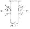
- FIG. 3 illustrates a similar apparatus 80 having a similar containment vessel 82, a similar discharge tube 84 and three similar filter assemblies 86a, 86b and 86c.
- the primary difference between apparatus 80 and apparatus 10 is that the tube 84 is supported vertically upward from the bottom of the containment vessel rather than being suspended downward from its top end.
- vessel 82 includes an inlet 88 at its top end and an outlet 90 at its bottom end.
- the gas inlet could be at position along the side of vessel 82B, along with a corresponding deflector plate, exactly as previously described in apparatus 10.
- the containment vessel does not include a dust hopper similar to hopper 38 but merely utilizes the bottom end of the containment vessel to collect dust.
- One. or more closable chutes 92 extending down from the bottom end of the containment vessel are provided for removing this dust.
- the overall vessel 82 is supported in the same manner as vessel 12, that is, by suitable support means 20.
- the two filter assemblies 86b and 86c may be identical to previously described assembly 16b, or assembly 86c may be provided with filter tubes of uniform lengths.
- the filter assembly 86a could be identical to assembly 16c to the extent that it utilizes its support plate to close the top end of the tube 84.
- its hood 94 is different than any of the other hoods in that it does not have to accommodate tube 84.
- the other difference between apparatus 80 and apparatus 10 is that the tube 84 is placed in compression at its support joint, whereas the tube 18 is placed in tension at its support joint. Otherwise, the various features and modifications associated with apparatus 10 are equally applicable to apparatus 80.
Landscapes
- Chemical & Material Sciences (AREA)
- Chemical Kinetics & Catalysis (AREA)
- Filtering Of Dispersed Particles In Gases (AREA)
- Filtration Of Liquid (AREA)
- Sanitary Device For Flush Toilet (AREA)
- Devices That Are Associated With Refrigeration Equipment (AREA)
- Harvester Elements (AREA)
- Polarising Elements (AREA)
- Separation By Low-Temperature Treatments (AREA)
- External Artificial Organs (AREA)
- Sampling And Sample Adjustment (AREA)
Priority Applications (1)
| Application Number | Priority Date | Filing Date | Title |
|---|---|---|---|
| AT84105459T ATE32664T1 (de) | 1983-05-20 | 1984-05-14 | Vertikal gestaffelter teilchenfilter. |
Applications Claiming Priority (2)
| Application Number | Priority Date | Filing Date | Title |
|---|---|---|---|
| US06/496,520 US4525184A (en) | 1983-05-20 | 1983-05-20 | Vertically tiered particle filtering apparatus |
| US496520 | 1990-03-20 |
Publications (3)
| Publication Number | Publication Date |
|---|---|
| EP0129053A2 EP0129053A2 (en) | 1984-12-27 |
| EP0129053A3 EP0129053A3 (en) | 1985-04-17 |
| EP0129053B1 true EP0129053B1 (en) | 1988-03-02 |
Family
ID=23972996
Family Applications (1)
| Application Number | Title | Priority Date | Filing Date |
|---|---|---|---|
| EP84105459A Expired EP0129053B1 (en) | 1983-05-20 | 1984-05-14 | Vertically tiered particle filtering apparatus |
Country Status (11)
| Country | Link |
|---|---|
| US (1) | US4525184A (ja) |
| EP (1) | EP0129053B1 (ja) |
| JP (1) | JPS6012115A (ja) |
| AT (1) | ATE32664T1 (ja) |
| AU (1) | AU561505B2 (ja) |
| CA (1) | CA1235376A (ja) |
| DE (1) | DE3469490D1 (ja) |
| DK (1) | DK244884A (ja) |
| ES (1) | ES532976A0 (ja) |
| NO (1) | NO159518C (ja) |
| ZA (1) | ZA843407B (ja) |
Cited By (2)
| Publication number | Priority date | Publication date | Assignee | Title |
|---|---|---|---|---|
| DE8914966U1 (ja) * | 1989-12-21 | 1990-02-15 | Deutsche Babcock Anlagen Ag, 4200 Oberhausen, De | |
| WO2014114549A1 (de) | 2013-01-25 | 2014-07-31 | Aixtron Se | Cvd-anlage mit partikelabscheider |
Families Citing this family (25)
| Publication number | Priority date | Publication date | Assignee | Title |
|---|---|---|---|---|
| US4760968A (en) * | 1987-06-30 | 1988-08-02 | Dravo Corporation | Integrated dust containment system for rotary crusher/breakers and the like |
| US4904287A (en) * | 1988-12-22 | 1990-02-27 | Electric Power Research Institute | Compact ceramic tube filter array high-temperature gas filtration |
| US4969937A (en) * | 1989-05-30 | 1990-11-13 | Electric Power Research Institute | Vertically tiered particle filtering apparatus |
| US5152815A (en) * | 1989-09-05 | 1992-10-06 | Zievers James F | Type 114 tiered filter |
| US5185019A (en) * | 1990-10-22 | 1993-02-09 | Westinghouse Electric Corp. | Filtering apparatus |
| US5143530A (en) * | 1990-10-22 | 1992-09-01 | Westinghouse Electric Corp. | Filtering apparatus |
| US5256175A (en) * | 1992-03-04 | 1993-10-26 | Zievers James F | Hot gas filter |
| TW227526B (ja) * | 1992-05-18 | 1994-08-01 | Shell Internat Res Schappj B V | |
| BE1006111A5 (nl) * | 1992-08-05 | 1994-05-17 | Seghers Engineering | Filter voor het filtreren van met partikels beladen gassen. |
| US5458665A (en) * | 1993-07-12 | 1995-10-17 | A. Ahlstrom Corporation | Apparatus for filtering gases |
| US5443806A (en) * | 1994-03-22 | 1995-08-22 | A. Ahlstrom Corporation | Treating exhaust gas from a pressurized fluidized bed reaction system |
| US5474585A (en) * | 1994-05-18 | 1995-12-12 | Pall Corporation | Filtering apparatus |
| US5453108A (en) * | 1994-05-18 | 1995-09-26 | A. Ahlstrom Corporation | Apparatus for filtering gases |
| US5531798A (en) * | 1994-05-26 | 1996-07-02 | Foster Wheeler Energia Oy | Eliminating ash bridging in ceramic filters |
| JP3066247B2 (ja) * | 1994-05-31 | 2000-07-17 | 日本碍子株式会社 | 集塵装置 |
| US5518513A (en) * | 1994-09-16 | 1996-05-21 | Mitsubishi Jukogyo Kabushiki Kaisha | Dust removing apparatus |
| DE19527311A1 (de) * | 1995-07-26 | 1997-01-30 | Lurgi Lentjes Babcock Energie | Verfahren und Vorrichtung zum Reinigen von staubbeladenem Gas |
| DE19527237A1 (de) * | 1995-07-26 | 1997-01-30 | Lurgi Lentjes Babcock Energie | Vorrichtung zum Reinigen von staubbeladenem Gas |
| US6579502B2 (en) * | 1999-03-29 | 2003-06-17 | Uop Llc | Liquid collector assembly for a reactor |
| TW500622B (en) * | 2000-12-04 | 2002-09-01 | Taeyang Tech Co Ltd | Gas scrubber system |
| BRPI0418279A (pt) * | 2003-12-19 | 2007-05-02 | Sintokogio Inc | elemento de cartucho para um coletor de poeira |
| JP2008514426A (ja) * | 2004-10-01 | 2008-05-08 | ハネウェル・インターナショナル・インコーポレーテッド | フィルタ及びその製造方法 |
| DE102006028293A1 (de) * | 2006-06-20 | 2007-12-27 | Walter Kuntschar | Verfahren zur Reinigung von Gasen aus einem Holzvergaser und Filter hierfür |
| CA2709976C (en) * | 2008-01-07 | 2014-04-15 | Von Gortz & Finger Techn. Enttwicklungs Ges.M.B.H. | Pyrolytic gas generator |
| CN110339631A (zh) * | 2018-04-03 | 2019-10-18 | 中国科学院大连化学物理研究所 | 一种煤热解气体高温在线除尘净化装置及其工作方法 |
Family Cites Families (16)
| Publication number | Priority date | Publication date | Assignee | Title |
|---|---|---|---|---|
| CA578549A (en) * | 1959-06-30 | M. Battey Everett | Diatomite filter system | |
| US655841A (en) * | 1899-11-08 | 1900-08-14 | Henry Burnett Watson | Filter. |
| US1000405A (en) * | 1910-10-29 | 1911-08-15 | Christopher J Healy | Varnish-filter. |
| US2317449A (en) * | 1941-10-31 | 1943-04-27 | Universal Oil Prod Co | Reactor |
| US2374976A (en) * | 1942-06-26 | 1945-05-01 | Briggs Clarlfier Company | Clarifying device |
| US2523793A (en) * | 1943-10-06 | 1950-09-26 | Bendix Aviat Corp | Compound filter |
| DE867780C (de) * | 1949-12-07 | 1954-02-01 | Reinhold Dipl-Ing Dr Phi Kamps | Staubabscheide-Anlage |
| DE1407941C3 (de) * | 1962-10-24 | 1979-04-19 | Demag Ag, 4100 Duisburg | Schlauchfilteranlage für Nieder- und Hochdruck-Trockengasreinigung |
| US3491518A (en) * | 1966-09-15 | 1970-01-27 | Ashland Oil Inc | Solid-gas separating means |
| NL172604C (nl) * | 1970-07-23 | 1983-09-16 | Interatom | Inrichting voor het continu afscheiden van metaaldampen of metaalaerosolen in vloeibare vorm uit gassen, in het bijzonder van natriumdamp of -druppeltjes uit het schutgas van een natriumgekoelde kernenergie-installatie. |
| US3986960A (en) * | 1974-06-03 | 1976-10-19 | Wire Philip J | Fluid filter |
| JPS53115207U (ja) * | 1977-02-21 | 1978-09-13 | ||
| ZA786014B (en) * | 1977-11-04 | 1979-10-31 | Nat Res Dev | Improvements in or relating to filtration apparatus |
| FR2454323B1 (fr) * | 1979-04-20 | 1988-04-22 | Degremont | Filtre a elements filtrants verticaux |
| US4264345A (en) * | 1979-09-12 | 1981-04-28 | American Air Filter Company, Inc. | Filter housing |
| US4289630A (en) * | 1979-12-10 | 1981-09-15 | Industrial Filter & Pump Mfg. Co. | Filter cake removal method and apparatus |
-
1983
- 1983-05-20 US US06/496,520 patent/US4525184A/en not_active Ceased
-
1984
- 1984-05-07 ZA ZA843407A patent/ZA843407B/xx unknown
- 1984-05-07 AU AU27732/84A patent/AU561505B2/en not_active Ceased
- 1984-05-14 DE DE8484105459T patent/DE3469490D1/de not_active Expired
- 1984-05-14 EP EP84105459A patent/EP0129053B1/en not_active Expired
- 1984-05-14 AT AT84105459T patent/ATE32664T1/de not_active IP Right Cessation
- 1984-05-17 DK DK244884A patent/DK244884A/da not_active Application Discontinuation
- 1984-05-18 ES ES532976A patent/ES532976A0/es active Granted
- 1984-05-18 NO NO842002A patent/NO159518C/no unknown
- 1984-05-18 CA CA000454657A patent/CA1235376A/en not_active Expired
- 1984-05-21 JP JP59102436A patent/JPS6012115A/ja active Granted
Cited By (3)
| Publication number | Priority date | Publication date | Assignee | Title |
|---|---|---|---|---|
| DE8914966U1 (ja) * | 1989-12-21 | 1990-02-15 | Deutsche Babcock Anlagen Ag, 4200 Oberhausen, De | |
| WO2014114549A1 (de) | 2013-01-25 | 2014-07-31 | Aixtron Se | Cvd-anlage mit partikelabscheider |
| DE102014100092A1 (de) | 2013-01-25 | 2014-07-31 | Aixtron Se | CVD-Anlage mit Partikelabscheider |
Also Published As
| Publication number | Publication date |
|---|---|
| CA1235376A (en) | 1988-04-19 |
| EP0129053A2 (en) | 1984-12-27 |
| AU2773284A (en) | 1984-11-22 |
| AU561505B2 (en) | 1987-05-07 |
| ES8504470A1 (es) | 1985-05-01 |
| NO842002L (no) | 1984-11-21 |
| US4525184A (en) | 1985-06-25 |
| DK244884A (da) | 1984-11-21 |
| ES532976A0 (es) | 1985-05-01 |
| EP0129053A3 (en) | 1985-04-17 |
| JPS6350044B2 (ja) | 1988-10-06 |
| ATE32664T1 (de) | 1988-03-15 |
| NO159518C (no) | 1989-01-11 |
| JPS6012115A (ja) | 1985-01-22 |
| DK244884D0 (da) | 1984-05-17 |
| ZA843407B (en) | 1984-12-24 |
| NO159518B (no) | 1988-10-03 |
| DE3469490D1 (en) | 1988-04-07 |
Similar Documents
| Publication | Publication Date | Title |
|---|---|---|
| EP0129053B1 (en) | Vertically tiered particle filtering apparatus | |
| US5562746A (en) | Air filter assembly for filtering air with particulate matter | |
| US4904287A (en) | Compact ceramic tube filter array high-temperature gas filtration | |
| US4955996A (en) | Top loading dust collector | |
| EP0762923B1 (en) | Eliminating ash bridging in ceramic filters | |
| EP0176362A2 (en) | Filter systems | |
| US5752999A (en) | Hot gas filtering apparatus | |
| EP0572063B1 (en) | Filtration module | |
| US5944859A (en) | Hot gas filter and system assembly | |
| US5474585A (en) | Filtering apparatus | |
| AU628573B2 (en) | Vertically tiered particle filtering apparatus | |
| US5037461A (en) | Filtration apparatus | |
| US5256175A (en) | Hot gas filter | |
| USRE34055E (en) | Vertically tiered particle filtering apparatus | |
| US5284498A (en) | Cylindrical filters in a tube sheet for cleaning high temperature gases | |
| US4553986A (en) | Filtering system and method of using same | |
| US5152815A (en) | Type 114 tiered filter | |
| US5453108A (en) | Apparatus for filtering gases | |
| CA2246643C (en) | Hot gas filtering apparatus | |
| GB2211437A (en) | A filter |
Legal Events
| Date | Code | Title | Description |
|---|---|---|---|
| PUAI | Public reference made under article 153(3) epc to a published international application that has entered the european phase |
Free format text: ORIGINAL CODE: 0009012 |
|
| AK | Designated contracting states |
Designated state(s): AT BE CH DE FR GB IT LI NL SE |
|
| PUAL | Search report despatched |
Free format text: ORIGINAL CODE: 0009013 |
|
| AK | Designated contracting states |
Designated state(s): AT BE CH DE FR GB IT LI NL SE |
|
| 17P | Request for examination filed |
Effective date: 19850604 |
|
| 17Q | First examination report despatched |
Effective date: 19860225 |
|
| GRAA | (expected) grant |
Free format text: ORIGINAL CODE: 0009210 |
|
| AK | Designated contracting states |
Kind code of ref document: B1 Designated state(s): AT BE CH DE FR GB IT LI NL SE |
|
| REF | Corresponds to: |
Ref document number: 32664 Country of ref document: AT Date of ref document: 19880315 Kind code of ref document: T |
|
| REF | Corresponds to: |
Ref document number: 3469490 Country of ref document: DE Date of ref document: 19880407 |
|
| ITF | It: translation for a ep patent filed |
Owner name: STUDIO TORTA SOCIETA' SEMPLICE |
|
| ET | Fr: translation filed | ||
| PLBE | No opposition filed within time limit |
Free format text: ORIGINAL CODE: 0009261 |
|
| STAA | Information on the status of an ep patent application or granted ep patent |
Free format text: STATUS: NO OPPOSITION FILED WITHIN TIME LIMIT |
|
| 26N | No opposition filed | ||
| ITTA | It: last paid annual fee | ||
| PGFP | Annual fee paid to national office [announced via postgrant information from national office to epo] |
Ref country code: NL Payment date: 19910531 Year of fee payment: 8 |
|
| PGFP | Annual fee paid to national office [announced via postgrant information from national office to epo] |
Ref country code: CH Payment date: 19910829 Year of fee payment: 8 Ref country code: DE Payment date: 19910829 Year of fee payment: 8 |
|
| PGFP | Annual fee paid to national office [announced via postgrant information from national office to epo] |
Ref country code: AT Payment date: 19910830 Year of fee payment: 8 Ref country code: GB Payment date: 19910830 Year of fee payment: 8 Ref country code: SE Payment date: 19910830 Year of fee payment: 8 |
|
| PGFP | Annual fee paid to national office [announced via postgrant information from national office to epo] |
Ref country code: FR Payment date: 19910906 Year of fee payment: 8 |
|
| PGFP | Annual fee paid to national office [announced via postgrant information from national office to epo] |
Ref country code: BE Payment date: 19911003 Year of fee payment: 8 |
|
| PG25 | Lapsed in a contracting state [announced via postgrant information from national office to epo] |
Ref country code: AT Effective date: 19920514 Ref country code: GB Effective date: 19920514 |
|
| PG25 | Lapsed in a contracting state [announced via postgrant information from national office to epo] |
Ref country code: SE Effective date: 19920515 |
|
| PG25 | Lapsed in a contracting state [announced via postgrant information from national office to epo] |
Ref country code: LI Effective date: 19920531 Ref country code: BE Effective date: 19920531 Ref country code: CH Effective date: 19920531 |
|
| BERE | Be: lapsed |
Owner name: ELECTRIC POWER RESEARCH INSTITUTE INC. Effective date: 19920531 |
|
| PG25 | Lapsed in a contracting state [announced via postgrant information from national office to epo] |
Ref country code: NL Effective date: 19921201 |
|
| GBPC | Gb: european patent ceased through non-payment of renewal fee |
Effective date: 19920514 |
|
| NLV4 | Nl: lapsed or anulled due to non-payment of the annual fee | ||
| PG25 | Lapsed in a contracting state [announced via postgrant information from national office to epo] |
Ref country code: FR Effective date: 19930129 |
|
| REG | Reference to a national code |
Ref country code: CH Ref legal event code: PL |
|
| PG25 | Lapsed in a contracting state [announced via postgrant information from national office to epo] |
Ref country code: DE Effective date: 19930202 |
|
| REG | Reference to a national code |
Ref country code: FR Ref legal event code: ST |
|
| EUG | Se: european patent has lapsed |
Ref document number: 84105459.6 Effective date: 19921204 |