EP0129011A2 - Device for purifying flue gases - Google Patents
Device for purifying flue gases Download PDFInfo
- Publication number
- EP0129011A2 EP0129011A2 EP84103931A EP84103931A EP0129011A2 EP 0129011 A2 EP0129011 A2 EP 0129011A2 EP 84103931 A EP84103931 A EP 84103931A EP 84103931 A EP84103931 A EP 84103931A EP 0129011 A2 EP0129011 A2 EP 0129011A2
- Authority
- EP
- European Patent Office
- Prior art keywords
- filter
- granulate
- granules
- filter housing
- ring
- Prior art date
- Legal status (The legal status is an assumption and is not a legal conclusion. Google has not performed a legal analysis and makes no representation as to the accuracy of the status listed.)
- Withdrawn
Links
Images
Classifications
-
- B—PERFORMING OPERATIONS; TRANSPORTING
- B01—PHYSICAL OR CHEMICAL PROCESSES OR APPARATUS IN GENERAL
- B01D—SEPARATION
- B01D46/00—Filters or filtering processes specially modified for separating dispersed particles from gases or vapours
- B01D46/30—Particle separators, e.g. dust precipitators, using loose filtering material
- B01D46/32—Particle separators, e.g. dust precipitators, using loose filtering material the material moving during filtering
- B01D46/34—Particle separators, e.g. dust precipitators, using loose filtering material the material moving during filtering not horizontally, e.g. using shoots
Abstract
Description
Die Erfindung betrifft eine Vorrichtung zum Reinigen von Rauchgasen, die unten in ein Filtergehäuse eingeführt, in einen vom Filtergehäuse umschlossenen, durch einen hülsenförmigen Granulatfilter gebildeten Innenraum geleitet und durch den Granulatfilter hindurch in einen diesen umgebenden Außenraum des Fil- tergehäuses gedrückt werden, aus dem das Reingas oben abgeführt wird, wobei das Filtergranulat durch ringförmige Leitvorrichtungen gehalten wird und eine innenliegende rotierende Abstreifeinrichtung vorgesehen ist, über die das verbrauchte Granulat einem Sammelbehälter zugeleitet wird.The invention relates to an apparatus for cleaning flue gases introduced at the bottom of a filter housing, passed into a space enclosed by the filter housing, formed by a sleeve-shaped granules filter interior and through the granular filter and into a surrounding outer space of the F il- tergehäuses be pressed from the the clean gas is removed at the top, the filter granules being held by annular guide devices and an internal rotating scraper device being provided, via which the used granules are fed to a collecting container.
Derartige Vorrichtungen sind erforderlich zum Reinigen der Rauchgase von festen oder gasförmigen Schadstoffen, zum Beispiel von Ruß oder bei Verwendung von Kalksteingranulat auch von Fluor-Wasserstoffen durch Trockensorption.Such devices are required for cleaning the flue gases from solid or gaseous pollutants, for example soot or, when using limestone granules, also from hydrogen fluoride by dry sorption.
Aus der ceramic forum international/Berichte der DKG, Band 58, von 1981, Nr. 6 "Fluor-Trockensorption im GSS-Sorptionsfilter" von B. Rüskamp ist ein Filter mit Kalksteingranulatfüllung bekannt, der hülsenförmig ausgebildet ist, wobei die Hülse aus mehreren Schichtringen besteht, die voneinander getrennt sind und in die das fluorbeladene Rauchgas radial eintritt, innerhalb der Ringe nahezu vertikal umgelenkt wird, und die Filterschicht gereinigt den außenliegenden Reingasraum verläßt.From the ceramic forum international / Reports of the DKG, Volume 58, from 1981, No. 6 "Fluorine dry sorption in the GSS sorption filter" by B. Rüskamp, a filter with limestone granulate filling is known, which is designed in the form of a sleeve, the sleeve being made of there is a plurality of layer rings which are separated from one another and into which the fluorine-laden flue gas radially enters, within which the rings are deflected almost vertically, and the cleaned filter layer leaves the external clean gas space.
Zwischen dem radialen Gaseintritt in die Schüttschichtringe und dem nahezu vertikalen Austritt soll die Geschwindigkeit der Abgase in der Schüttschicht verringert werden, um auf diese Weise die Verweilzeit innerhalb der Filterschicht zu erhöhen.The velocity of the exhaust gases in the bed layer is to be reduced between the radial gas entry into the bed layer rings and the almost vertical outlet, in order in this way to increase the dwell time within the filter layer.
Das Filtermaterial wird über einen Verteilkonus am oberen Ende der Filterzelle durch Verteilrohre in die einzelnen Schüttschichtringe eingebracht, in denen es radial nach innen fließt. Mit rotierenden Abstreifern wird der Überlauf des verbrauchten Filtermaterials in Fangtaschen, die in jeder Schüttschichtebene angeordnet sind, abgestreift und über einen Fallkanal einem Sammelkonus am unteren Ende des Filters zugeführt.The filter material is introduced through a distribution cone at the upper end of the filter cell through distribution pipes into the individual bed layers in which it flows radially inwards. With rotating wipers, the overflow of the used filter material is wiped off in collecting pockets, which are arranged in every bed layer, and fed to a collecting cone at the lower end of the filter via a drop channel.
Hierbei ist nachteilig, daß die Konstruktion der Schichtringe sowie der Granulatzu- und -abführung aufwendig ist und die großen Metallflächen bei aggresiven Rauchgasen dem Säureangriff ausgesetzt sind. Die Umlenkung des Granulats in den Schichtringen, die dessen Ausfließen verhindert und auch die Umlenkung der Rauchgase bewirkt, resultiert in einer geringen Filtereinlaßfläche, so daß eine große Zahl von Schichtringen erforderlich ist und die Vorrichtung sehr groß wird.The disadvantage here is that the construction of the layer rings as well as the granulate feed and discharge is complex and the large metal surfaces are exposed to acid attack in the case of aggressive smoke gases. The deflection of the granulate in the layer rings, which prevents it from flowing out and also causes the deflection of the flue gases, results in a small filter inlet area, so that a large number of layer rings is required and the device becomes very large.
Eine Geschwindigkeitsverringerung der Rauchgase in der Filterschicht wird bestenfalls gegenüber der Geschwindigkeit in der Einlaßöffnung erreicht. Eine nennenswerte Verringerung der Geschwindigkeit gegenüber dem Hülseninnenraum demgegenüber würde eine große Filterstärke oder ebenfalls eine große Zahl von Schichtringen erfordern.At best, the velocity of the flue gases in the filter layer is reduced compared to the velocity in the inlet opening. A significant reduction in speed compared to the interior of the sleeve, on the other hand, would require a large filter thickness or a large number of layer rings.
Aufgabe der Erfindung ist es demnach, einen Filter zu schaffen, der mit möglichst wenig, den aggressiven Rauchgasen an der Rohgasseite des Filters ausgesetzten Metallflächen auskommt, bei dem keine Filterfläche durch Ringwandungen oder ähnliches verlorengeht, bei dem geringe Rauchgasgeschwindigkeiten bei relativ kleiner Baugröße in der Filterschicht erreicht werden, der einen geringen mechanischen Aufwand und geringe Antriebsleistung erfordert.The object of the invention is therefore to provide a filter that with the least possible, the aggressive smoke gases on the Metal surfaces exposed to the raw gas side of the filter, in which no filter surface is lost due to ring walls or the like, in which low flue gas speeds are achieved in the filter layer with a relatively small size, which requires little mechanical effort and low drive power.
Die Aufgabe der Erfindung wird durch die im kennzeichnenden Teil des Anspruchs 1 beschriebenen Maßnahmen gelöst.The object of the invention is achieved by the measures described in the characterizing part of
Die mit der Erfindung erzielbaren Vorteile bestehen insbesondere darin, daß der Filter relativ klein ist, eine große Filterfläche aufweist mit relativ wenig zum Rauchgas exponierte Metallflächen, wobei der mechanische und der Energieaufwand gering ist.The advantages that can be achieved with the invention are, in particular, that the filter is relatively small, has a large filter area with relatively little metal surface exposed to the flue gas, and the mechanical and energy expenditure is low.
Vorteilhafte Ausgestaltungen der Erfindung sind in den Unteransprüchen enthalten.Advantageous embodiments of the invention are contained in the subclaims.
Ein Ausführungsbeispiel der Erfindung ist in der Zeichnung dargestellt und wird im folgenden näher beschrieben. Es zeigen:
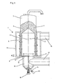
- Fig. 1 einen Schnitt durch die Filteranlage,
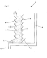
- Fig. 2 einen Detailschnitt des Filters.
- 1 shows a section through the filter system,
- Fig. 2 shows a detail section of the filter.
Die Filteranlage 1 besteht aus einem über einem Filtergehäuse 9 angeordneten Silo 2 mit einem Verteilkonus 3 an dessen unteren Seite, mit dem das Granulat 4 ringförmig nach außen in den Granulatfilter 5 geleitet wird. Der innerhalb des Gehäuses 9 befindliche hülsenförmige Granulatfilter 5 besteht aus übereinander angeordneten äußeren Ringen 6, die konisch nach innen geneigt sind, übereinander angeordneten inneren Ringen 7, die nach außen konisch geneigt sind, und dem Granulat 4, das im Ringspalt zwischen den Ringen 6 und 7 nach unten strömt.The
Der unterste äußere Ring 6' ist breiter als die darüberliegenden, so daß er als Fangvorrichtung für evtl. überlaufendes Granulat dient. Der unterste innere Ring 7 ist in einem Abstand B zum Boden 8 des Filtergehäuses 9 angeordnet, so daß das Granulat 4 unter diesem untersten Ring 7 nach innen abfließen kann.The lowermost outer ring 6 'is wider than the ones above it, so that it serves as a catching device for possibly overflowing granules. The lowest
Die horizontale Breite C der Ringe 6 und 7 (Fig. 2) sowie der Abstand C zwischen den Ringen 6 und 7 ist so gewählt, daß bei Berücksichtigung eines Böschungswinkels α des Granulats 4 kein Überlauf stattfindet.The horizontal width C of the
Am Boden 8 ist ein zylindrischer Fangraum 10 vorgesehen, der einen Durchmesser A hat, der in einem solchen Verhältnis zum Abstand B zwischen dem untersten inneren Ring 7 und dem Boden 8 steht, daß das Granulat 4 mit dem Böschungswinkel α nicht über die Kante 11 in den Fangraum 10 laufen kann, der gleichzeitig den Einlaß 12 für das verschmutzte Rauchgas aufweist.At the
Der Fangraum 10 hat einen nach unten verjüngten Abschnitt. An seiner Unterseite befindet sich seitlich ein Granulatablaß 13 mit Zellradschleuse 14 zum Ablassen des verbrauchten Granulats 4.The
Das Reingas wird zwischen Granulatfilter 5 und dem Filtergehäuse 9 gesammelt und mit dem Leitungsanschluß 15 abgeführt.The clean gas is collected between the
Im Fangraum 10 ist eine Abstreifvorrichtung 17 gelagert, die programmiert innerhalb des äußeren untersten Ringes 6' rotiert und das verbrauchte Granulat 4 in den Fangraum 10 abstreift mit einem Antrieb 16, der im Boden des Fangraumes 10 gelagert ist. Das Granulat 4 läuft aus dem Silo 2 selbsttätig in den Granulatfilter 5 nach.A
Claims (5)
daß der Granulatfilter (5) aus übereinander angeordneten äußeren Ringen (6) gebildet wird, die konisch nach innen geneigt sind und deren unterster Ring (6') breiter ist, um als Fangvorrichtung für überlaufendes Granulat (4) zu dienen, und aus inneren Ringen (7) besteht, die konisch nach außen geneigt sind, wobei deren unterster Ring im Abstand (B) zum Boden (8) des Filtergehäuses (9) angeordnet ist, so daß das Granulat (4) darunter in das Innere des Filtergehäuses (9) abfließen kann, und daß der vertikale Abstand (C) der Ringe (6) und (7) sowie die Ringbreite (D) derart sind, daß mit einem Böschungswinkel (oe) das fließende Granulat (4) nicht überläuft.1. Device for cleaning flue gases, which are introduced at the bottom into a filter housing, introduced into an interior space enclosed by the filter housing and formed by a sleeve-shaped granulate filter, and pressed through the granulate filter into an outer space of the filter housing surrounding it, from which the clean gas is discharged. wherein the filter granules are held by ring-shaped guide devices and an internal, rotating scraper device is provided, via which the used granules are fed to a collecting container, characterized in that
that the granulate filter (5) is formed from superposed outer rings (6) which are conically inclined inwards and whose lower ring (6 ') is wider to serve as a catcher for overflowing granules (4) and from inner rings (7), which are conically inclined outwards, the lowest ring in the Distance (B) to the bottom (8) of the filter housing (9) is arranged so that the granules (4) can flow underneath into the interior of the filter housing (9), and that the vertical distance (C) of the rings (6) and (7) and the ring width (D) are such that the flowing granulate (4) does not overflow with an angle of repose (oe).
Applications Claiming Priority (2)
| Application Number | Priority Date | Filing Date | Title |
|---|---|---|---|
| DE19833317906 DE3317906A1 (en) | 1983-05-17 | 1983-05-17 | DEVICE FOR PURIFYING SMOKE GASES |
| DE3317906 | 1983-05-17 |
Publications (2)
| Publication Number | Publication Date |
|---|---|
| EP0129011A2 true EP0129011A2 (en) | 1984-12-27 |
| EP0129011A3 EP0129011A3 (en) | 1985-03-27 |
Family
ID=6199182
Family Applications (1)
| Application Number | Title | Priority Date | Filing Date |
|---|---|---|---|
| EP84103931A Withdrawn EP0129011A3 (en) | 1983-05-17 | 1984-04-09 | Device for purifying flue gases |
Country Status (2)
| Country | Link |
|---|---|
| EP (1) | EP0129011A3 (en) |
| DE (1) | DE3317906A1 (en) |
Citations (3)
| Publication number | Priority date | Publication date | Assignee | Title |
|---|---|---|---|---|
| CH99514A (en) * | 1922-03-13 | 1923-06-16 | B Fiechter Louis | Drum filter for gaseous media. |
| DE2545218A1 (en) * | 1975-10-09 | 1977-04-21 | Babcock Ag | PROCESS AND DEVICE FOR REMOVING UNWANTED COMPONENTS FROM EXHAUST GASES |
| GB2067918A (en) * | 1980-01-26 | 1981-08-05 | Buechl A Kalk Portland | Apparatus for the treatment of a gas stream with a particulate solid |
Family Cites Families (2)
| Publication number | Priority date | Publication date | Assignee | Title |
|---|---|---|---|---|
| DE2820650C3 (en) * | 1978-05-11 | 1981-07-16 | Viktor Dipl.-Ing. Graz Weiss | Device for replacing a granular filter material of a gas cleaning system that forms the filling of a filter |
| GB2090773A (en) * | 1980-12-18 | 1982-07-21 | Gen Electric | Electrostatically augmented granular bed filter for high temperature particulate removal |
-
1983
- 1983-05-17 DE DE19833317906 patent/DE3317906A1/en not_active Withdrawn
-
1984
- 1984-04-09 EP EP84103931A patent/EP0129011A3/en not_active Withdrawn
Patent Citations (3)
| Publication number | Priority date | Publication date | Assignee | Title |
|---|---|---|---|---|
| CH99514A (en) * | 1922-03-13 | 1923-06-16 | B Fiechter Louis | Drum filter for gaseous media. |
| DE2545218A1 (en) * | 1975-10-09 | 1977-04-21 | Babcock Ag | PROCESS AND DEVICE FOR REMOVING UNWANTED COMPONENTS FROM EXHAUST GASES |
| GB2067918A (en) * | 1980-01-26 | 1981-08-05 | Buechl A Kalk Portland | Apparatus for the treatment of a gas stream with a particulate solid |
Also Published As
| Publication number | Publication date |
|---|---|
| DE3317906A1 (en) | 1983-10-06 |
| EP0129011A3 (en) | 1985-03-27 |
Similar Documents
| Publication | Publication Date | Title |
|---|---|---|
| DE2543063C2 (en) | Gas filter | |
| DE4418045A1 (en) | Plant for wet cleaning of exhaust gases | |
| DE2013192A1 (en) | Wet cleaner | |
| DE2649180C2 (en) | Eddy current column for cleaning gases | |
| DE3541370A1 (en) | LIQUID / GAS SEPARATOR | |
| DE1758357A1 (en) | Device for quenching and / or washing hot gases | |
| EP0270531B1 (en) | Moving bed reactor | |
| DE1645762A1 (en) | Device for separating liquid petroleum products from a petroleum product-water mixture | |
| DE3002773A1 (en) | GAS CLEANING FILTER | |
| DE2301469C3 (en) | Gas scrubber | |
| DE1571778A1 (en) | Separator for separating dust | |
| DE3344571A1 (en) | Sorption unit for purifying industrial exhaust gases | |
| EP0558873B1 (en) | Installation for the separation of aerosols contained in the air from a nuclear reactor containment | |
| EP0490202A1 (en) | Activated carbon filter for separating noxious gases, such as dioxins and furans, from flue gases before entering the chimney | |
| DE1807327A1 (en) | Process for separating dust particles from a gas and device for carrying out this process | |
| DE3217146C2 (en) | ||
| EP0129011A2 (en) | Device for purifying flue gases | |
| DE2509123A1 (en) | WET LAUNDRY | |
| DE1244718B (en) | Device for cleaning a gas containing dust by means of foam | |
| CH637845A5 (en) | METHOD AND DEVICE FOR INTERMITTENT, REGENERATIVE CLEANING OF A FILTER BED. | |
| DE2726083A1 (en) | WET CLEANING DEVICE | |
| DE3309518C2 (en) | Separator for separating fine-grained particles from a gaseous medium | |
| DE2163735B2 (en) | DEVICE FOR SEPARATING LIQUID DROPS FROM A FLOWING GASEOUS MEDIUM | |
| DE2305234A1 (en) | METHOD AND DEVICE FOR DISCHARGING GRAINY MATERIAL FROM A CONTAINER | |
| DE3531416A1 (en) | Gas scrubber |
Legal Events
| Date | Code | Title | Description |
|---|---|---|---|
| PUAI | Public reference made under article 153(3) epc to a published international application that has entered the european phase |
Free format text: ORIGINAL CODE: 0009012 |
|
| AK | Designated contracting states |
Designated state(s): AT BE FR GB IT NL |
|
| PUAL | Search report despatched |
Free format text: ORIGINAL CODE: 0009013 |
|
| AK | Designated contracting states |
Designated state(s): AT BE FR GB IT NL |
|
| STAA | Information on the status of an ep patent application or granted ep patent |
Free format text: STATUS: THE APPLICATION HAS BEEN WITHDRAWN |
|
| 18W | Application withdrawn |
Withdrawal date: 19850401 |
|
| RIN1 | Information on inventor provided before grant (corrected) |
Inventor name: LINGL, HANS |