EP0128879A1 - Device for recovering heat from gas operated ranges - Google Patents
Device for recovering heat from gas operated ranges Download PDFInfo
- Publication number
- EP0128879A1 EP0128879A1 EP84830169A EP84830169A EP0128879A1 EP 0128879 A1 EP0128879 A1 EP 0128879A1 EP 84830169 A EP84830169 A EP 84830169A EP 84830169 A EP84830169 A EP 84830169A EP 0128879 A1 EP0128879 A1 EP 0128879A1
- Authority
- EP
- European Patent Office
- Prior art keywords
- gas operated
- tubular duct
- duct
- recovering device
- heat recovering
- Prior art date
- Legal status (The legal status is an assumption and is not a legal conclusion. Google has not performed a legal analysis and makes no representation as to the accuracy of the status listed.)
- Withdrawn
Links
Images

Classifications
-
- F—MECHANICAL ENGINEERING; LIGHTING; HEATING; WEAPONS; BLASTING
- F24—HEATING; RANGES; VENTILATING
- F24C—DOMESTIC STOVES OR RANGES ; DETAILS OF DOMESTIC STOVES OR RANGES, OF GENERAL APPLICATION
- F24C13/00—Stoves or ranges with additional provisions for heating water
Definitions
- the present invention relates to a device for recovering heat from gas operated ranges of the type used at home,restaurants,hotels and the like.
- the total amount of heat (in the form of fumes,combustion products and radiating power) produced by a gas operated range during its operation consists of the following:
- the task of the present invention is to provide such a device which is able of completely or at least substantially recovering those heat portions which were not used during the food cooking process,without subtracting from the cooking process itself the power required thereby which,as it is known,changes depending on the contingent needs.
- a heat recovering device characterized in that it comprises at least a tubular duct encompassing at least a flame of a gas operated range,said tubular duct being supported by supporting means and being coupled,at the two ends thereof,to a duct for supplying the liquid to be heated and respectively to a duct for removing the heated liquid.
- the above mentioned tubular duct encompasses all of the flames of the gas operated range.
- the liquid passing through said tubular duct consists of water,and the mentioned tubular duct is coupled,from one side,to the home water supplyi network and,from the other side,to a home water heater device.
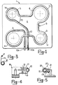
- a gas operated range of the type having four flames 2,3,4 and 5 and on the top surface 6 whereof there is removably associated a grill member 7 (fig.2) for supporting casseroles,pans and the like vessels used for cooking food and generally indicated at 8.
- a heat recovering device is supported on the top surface 6 of the gas operated range l,as it will be illustrated in a more detailed way thereinafter.
- the heat recovering device 9 comprises essentially a tubular duct 10 which encompasses,in a continuous way,all of the flames of the gas operated range.In particular,at the mentioned flames,annular portions 11,12,13 and 14 are formed in the tubular duct 10,not completely closed on themselves, in order to leave an acces space to the flames,for example for electrical lighters,not shown.
- the position of the mentioned tubular duct 10 with respect to the flames from 2 to 5 of the gas operated range 1 and the diameter of the annular portions from 11 to 14 of the tubular duct 10 are so selected that the heat recovering device 9 according to the present invention has,from one side,a satisfactory efficiency and,from the other hand,does not impair the thermal efficiency of the gas operated range thereto it is applied.
- tubular duct 10 be located immediately under the grill 7, and that the mentioned annular portions,formed by said tubular duct 10,have an inner diameter substantially equal to the outer diameter of the flame of the corresponding flame element of the range,as it is in its "maximnm" position, in such a way as to be touched thereby.
- the supporting means of the heat recovering device 9 may be of a different type,for example of the type schematically illustrated in figs.4 and 5.
- fig.4 there is illustrated a bracket or crancked lever supporting member 16, which is particularly useful for large size gas operated ranges,and which is provided with a forkshaped horizontal wing,the legs 17,18 whereof are effective to be resiliently deformed and'clamped by a screw 19.
- a supporting member 20 also of crancked configuration,which is particularly useful for small size gas operated ranges, such as the home ranges.
- a resilient ring 22 At the end portion of the horizontal wing 21 of the supporting member 20 there is formed a resilient ring 22, which is effective to be clamped or "closed” by threaded means 23,to be arranged about the tubular duct 10.
- Fig.6 schematically illustrates a further supporting member 24 for the tubular duct 10.
- that supporting member 24 consists of a metal cylindrical portion which encompasses a respective flame of the range 1 and in the inside whereof there is welded or affixed in any other suitable ways a corresponding annular portion of the tubular duct itself.
- the mentioned cylindrical portion is advantageously arranged above the grill 7 and is is to be provided with one or more openings 25 in order to facilitate the exiting of the fumes or combustion products.
- Said tubular portion 24 forms by itself the means for supporting the pan or cooking vessel.
- tubular duct 10 may also be welded or affixed in any other suitable ways outside of the tubular portion 24 in such a way as to form thereon two or more complete turns.
- the end portions 10a,10b of said tubular duct 10 are respectively communicated with a duct,not shown,for supplying the liquid to be heated(for example water) and with a duct for delivering the heated liquid.
- tubular duct 10 which is preferably made from steel,has a circular cross-section;however it may also have a quadrilateral or polygonal cross-section depending on the use needs and it may be smooth as in the illustrated case,or of finned configuration in order to increase the thermal exchange surface.
- the heat recovering device may be coupled to a tank, not shown, which is thermally insulated as a conventional water heater.More specifically that tank will be coupled to the water supply network and the coupling may consist of a simple cock to be opened and closed by the user together with a floating member for holding the level constant.
- the heat recovering device according to the present invention may be used as an integrating or economizing device in heating systems and/or electrical water heaters thereto it may be coupled in a very simple and economical way,according to conventional methods.
- the main advantage is achieved of using a lot of the heat which would be otherwise dispersed for heating a liquid,for example and preferably water,with a consequent great saving of power.
- the heat recovering device according to the invention provided "indirect" advantages, such as an improved thermal efficiency of the range since it improves the “conveying" of the fumes and combustion products along the walls of the pans;moreover it improves the efficiency of the sucking hood, owing to the improved conveying of the combustion fumes.
- advantages such as an improved thermal efficiency of the range since it improves the "conveying" of the fumes and combustion products along the walls of the pans;moreover it improves the efficiency of the sucking hood, owing to the improved conveying of the combustion fumes.
- a reduced amount of CO 2 released to the room of the gas operated range provided with a heat recovering device according to the present invention.
Abstract
A heat recovering device for gas operated ranges of the type used at homes, restaurants and hotels comprises a tubular duct (10) encompassing, in a continuous way, all of the flames (2, 3, 4 and 5) of the range, the tubular duct being supported by supporting means (15, 16, 20) and coupled, at the two ends thereof, (10a, 10b), respectively to a duct for supplying the liquid to be heated and to a duct for removing the heated liquid.
Description
- The present invention relates to a device for recovering heat from gas operated ranges of the type used at home,restaurants,hotels and the like.
- As it is known the total amount of heat (in the form of fumes,combustion products and radiating power) produced by a gas operated range during its operation consists of the following:
- 1) a first portion which is transmitted to the cooking vessels and then removed through the sucking head and from the room thereat the range is installed,with the exception of a small heat portion possibly absorbed by endothermal reactions occuring during the cooking of the food;
- 2) a second portion which is released into the room thereat the range is located and is due to the combustion products,fumes,radiations not directly involving the cooking vessels and which are removed through the sucking hood;
- 3) a third portion which is removed through the sucking hood(or dispersed through the room as a sucking hood is lacking) without touching the cooking vessels.
- Of the above mentioned portions,only that transmitted to the cooking vessels may be considered as the used one,whereas the remaining ones have represented up to now a great loss of thermal power.
- Thus the task of the present invention is to provide such a device which is able of completely or at least substantially recovering those heat portions which were not used during the food cooking process,without subtracting from the cooking process itself the power required thereby which,as it is known,changes depending on the contingent needs.
- According to one aspect of the present invention that task is achieved by a heat recovering device characterized in that it comprises at least a tubular duct encompassing at least a flame of a gas operated range,said tubular duct being supported by supporting means and being coupled,at the two ends thereof,to a duct for supplying the liquid to be heated and respectively to a duct for removing the heated liquid.
- Advantageously,the above mentioned tubular duct encompasses all of the flames of the gas operated range.
- According to a further aspect of the present invention, the liquid passing through said tubular duct consists of water,and the mentioned tubular duct is coupled,from one side,to the home water supplyi network and,from the other side,to a home water heater device.
- Further characteristics and advantages of the present invention will become more apparent hereinafter from the following detailed description of an exemplary embodiment of a heat recovering device according to the invention,being illustrated in the accompanying drawings,where:
- fig.l is a schematic plan view of a gas operated range including a heat recovering device according to the present invention;
- fig.2 is a cross-section elevation view illustrating a top portion of the gas operated range illustrated in fig.l;
- figs. 3 to 5 represent schematically and by a partial cross-sectional view some variations of means for supporting a heat recovering device according to the present invention;and
- fig.6 is a schematic cross-sectional,partial view illustrating a further embodiment of the means for supporting the heat recovering device according to the invention.
- With reference to the mentioned figures, at 1 there is schematically indicated the top portion of a gas operated range,of the type having four
flames top surface 6 whereof there is removably associated a grill member 7 (fig.2) for supporting casseroles,pans and the like vessels used for cooking food and generally indicated at 8. - A heat recovering device according to the present invention,overally indicated at 9,is supported on the
top surface 6 of the gas operated range l,as it will be illustrated in a more detailed way thereinafter. - The heat recovering
device 9 comprises essentially atubular duct 10 which encompasses,in a continuous way,all of the flames of the gas operated range.In particular,at the mentioned flames,annular portions tubular duct 10,not completely closed on themselves, in order to leave an acces space to the flames,for example for electrical lighters,not shown. - The position of the mentioned
tubular duct 10 with respect to the flames from 2 to 5 of the gas operated range 1 and the diameter of the annular portions from 11 to 14 of thetubular duct 10 are so selected that theheat recovering device 9 according to the present invention has,from one side,a satisfactory efficiency and,from the other hand,does not impair the thermal efficiency of the gas operated range thereto it is applied. - In the practice,in order to meet the above mentioned need,it is advantageous that the
tubular duct 10 be located immediately under the grill 7, and that the mentioned annular portions,formed by saidtubular duct 10,have an inner diameter substantially equal to the outer diameter of the flame of the corresponding flame element of the range,as it is in its "maximnm" position, in such a way as to be touched thereby. - In order to support the
tubular duct 10 with all of the related annular portions from 11 to 14 at the above mentioned position,there are advantageously provided hook members l5,suspended atop of the grill 7 and engaged at the bottom with thetubular duct 10 in order to hold the latter suspended at a suitable height with respect to the top surface of the gas operated range. - It should be noted that the supporting means of the
heat recovering device 9 according to the present invention may be of a different type,for example of the type schematically illustrated in figs.4 and 5.In fig.4 there is illustrated a bracket or cranckedlever supporting member 16, which is particularly useful for large size gas operated ranges,and which is provided with a forkshaped horizontal wing,thelegs screw 19. - In fig.5 there is illustrated a supporting member 20,also of crancked configuration,which is particularly useful for small size gas operated ranges, such as the home ranges.At the end portion of the
horizontal wing 21 of the supporting member 20 there is formed aresilient ring 22,which is effective to be clamped or "closed" by threadedmeans 23,to be arranged about thetubular duct 10. - Fig.6 schematically illustrates a further supporting
member 24 for the tubular duct 10.More specifically, that supportingmember 24 consists of a metal cylindrical portion which encompasses a respective flame of the range 1 and in the inside whereof there is welded or affixed in any other suitable ways a corresponding annular portion of the tubular duct itself. - The mentioned cylindrical portion is advantageously arranged above the grill 7 and is is to be provided with one or
more openings 25 in order to facilitate the exiting of the fumes or combustion products.Saidtubular portion 24 forms by itself the means for supporting the pan or cooking vessel. - It should be noted that the
tubular duct 10 may also be welded or affixed in any other suitable ways outside of thetubular portion 24 in such a way as to form thereon two or more complete turns. - The
end portions tubular duct 10 are respectively communicated with a duct,not shown,for supplying the liquid to be heated(for example water) and with a duct for delivering the heated liquid. - More specifically, the
tubular duct 10, which is preferably made from steel,has a circular cross-section;however it may also have a quadrilateral or polygonal cross-section depending on the use needs and it may be smooth as in the illustrated case,or of finned configuration in order to increase the thermal exchange surface. - The heat recovering
device 9 according to the present invention may be coupled to a cold water cock,and the water,after heating,may be directly used.In the absence of water circulation through thetubular duct 10, theheat recovering device 9 would be susceptible to become red- hot at some regions whereof.This, on the other hand,will be not a risk since the small steam jet which will be formed as the water delivery is started would be caused to condense in theportion 10b at the outlet of thetubular duct 10,which portion in that case would be coiled and downwardly oriented. - The heat recovering device according to the present invention may be coupled to a tank, not shown, which is thermally insulated as a conventional water heater.More specifically that tank will be coupled to the water supply network and the coupling may consist of a simple cock to be opened and closed by the user together with a floating member for holding the level constant.
- Moreover the heat recovering device according to the present invention may be used as an integrating or economizing device in heating systems and/or electrical water heaters thereto it may be coupled in a very simple and economical way,according to conventional methods.
- As a heat recovering device according to the present invention is installed on a gas operated range, the main advantage is achieved of using a lot of the heat which would be otherwise dispersed for heating a liquid,for example and preferably water,with a consequent great saving of power.
- Moreover the heat recovering device according to the invention provided "indirect" advantages, such as an improved thermal efficiency of the range since it improves the "conveying" of the fumes and combustion products along the walls of the pans;moreover it improves the efficiency of the sucking hood, owing to the improved conveying of the combustion fumes.To this connection it has been observed a reduced amount of CO2 released to the room of the gas operated range provided with a heat recovering device according to the present invention.
Claims (4)
1- A heat recovering device for gas operated ranges of the type used at homes,restaurants,hotels and the like,characterized in that it comprises at least a tubular duct (10) encompassing at least a flame (2,3,4,5) of a gas operated range (l),said tubular duct (10) being supported by supporting means (15,16,20) and being coupled,at the two ends whereof,(10a,10b), to a duct for supplying the liquid to be heated and respectively to a duct for removing the heated liquid.
2- A heat recovering device according to claim 1, characterized in that said tubular duct (10) encompasses all of the flames (2,3,4,5) of said gas operated range.
3- A heat recovering device according to claim 2, characterized in that in said tubular duct (10) and at the flames (2,3,4,5) of said gas operated range (1) there are formed annular portions (11,12,13,14) which are non completely closed on themselves in order to leave an acces space to said flames for example by a lighter.
4- A heat recovering device according to claim 1, characterized in that the liquid passing through said tubular duct consists of water,said tubular duct (10) being coupled,at one side,to the water supply network and,at the other side,to a home water heater device.
Applications Claiming Priority (2)
| Application Number | Priority Date | Filing Date | Title |
|---|---|---|---|
| IT2150983 | 1983-06-07 | ||
| IT8321509A IT1212749B (en) | 1983-06-07 | 1983-06-07 | HEAT RECOVERY FROM GAS COOKERS. |
Publications (1)
| Publication Number | Publication Date |
|---|---|
| EP0128879A1 true EP0128879A1 (en) | 1984-12-19 |
Family
ID=11182856
Family Applications (1)
| Application Number | Title | Priority Date | Filing Date |
|---|---|---|---|
| EP84830169A Withdrawn EP0128879A1 (en) | 1983-06-07 | 1984-06-05 | Device for recovering heat from gas operated ranges |
Country Status (2)
| Country | Link |
|---|---|
| EP (1) | EP0128879A1 (en) |
| IT (1) | IT1212749B (en) |
Cited By (4)
| Publication number | Priority date | Publication date | Assignee | Title |
|---|---|---|---|---|
| AT393020B (en) * | 1987-11-03 | 1991-07-25 | Vaillant Gmbh | Burner, in particular gas burner |
| DE19758023A1 (en) * | 1997-12-29 | 1999-07-01 | Volkswagen Ag | Gas cooker, particularly for camping vehicle |
| WO2001039641A2 (en) * | 1999-12-01 | 2001-06-07 | Twan Poa Lau | A cooking accessory |
| GB2442055A (en) * | 2006-09-19 | 2008-03-26 | Yin Lun Allen Wong | Heat recovery from a Chinese wok cooker with a folded tube within a ring |
Citations (4)
| Publication number | Priority date | Publication date | Assignee | Title |
|---|---|---|---|---|
| US1404134A (en) * | 1920-07-01 | 1922-01-17 | Meister Daniel Joseph | Water-heating apparatus |
| US1439490A (en) * | 1921-03-07 | 1922-12-19 | William A Siebert | Water heater |
| US1481665A (en) * | 1922-02-10 | 1924-01-22 | William J Elliott | Water heater for stoves |
| DE2647740A1 (en) * | 1976-10-22 | 1978-04-27 | Georg Graetzer | Water heater built into gas cooker top - has pipe section between supply and return formed as endless looped pipe |
-
1983
- 1983-06-07 IT IT8321509A patent/IT1212749B/en active
-
1984
- 1984-06-05 EP EP84830169A patent/EP0128879A1/en not_active Withdrawn
Patent Citations (4)
| Publication number | Priority date | Publication date | Assignee | Title |
|---|---|---|---|---|
| US1404134A (en) * | 1920-07-01 | 1922-01-17 | Meister Daniel Joseph | Water-heating apparatus |
| US1439490A (en) * | 1921-03-07 | 1922-12-19 | William A Siebert | Water heater |
| US1481665A (en) * | 1922-02-10 | 1924-01-22 | William J Elliott | Water heater for stoves |
| DE2647740A1 (en) * | 1976-10-22 | 1978-04-27 | Georg Graetzer | Water heater built into gas cooker top - has pipe section between supply and return formed as endless looped pipe |
Cited By (6)
| Publication number | Priority date | Publication date | Assignee | Title |
|---|---|---|---|---|
| AT393020B (en) * | 1987-11-03 | 1991-07-25 | Vaillant Gmbh | Burner, in particular gas burner |
| DE19758023A1 (en) * | 1997-12-29 | 1999-07-01 | Volkswagen Ag | Gas cooker, particularly for camping vehicle |
| WO2001039641A2 (en) * | 1999-12-01 | 2001-06-07 | Twan Poa Lau | A cooking accessory |
| SG87063A1 (en) * | 1999-12-01 | 2002-03-19 | Twan Poa Lau | A cooking accessory |
| WO2001039641A3 (en) * | 1999-12-01 | 2002-09-12 | Twan Poa Lau | A cooking accessory |
| GB2442055A (en) * | 2006-09-19 | 2008-03-26 | Yin Lun Allen Wong | Heat recovery from a Chinese wok cooker with a folded tube within a ring |
Also Published As
| Publication number | Publication date |
|---|---|
| IT1212749B (en) | 1989-11-30 |
| IT8321509A0 (en) | 1983-06-07 |
Similar Documents
| Publication | Publication Date | Title |
|---|---|---|
| EP1441628B1 (en) | An interchangeable multi-purpose cooking apparatus | |
| US7708006B2 (en) | Removable flame heat regulating apparatus including an inner hollow shell and an outer wall for a burner of a gas stove | |
| US3824984A (en) | Charcoal grill conversion apparatus | |
| US4660542A (en) | Cooking system with closed loop heat transfer means | |
| AU2002233013A1 (en) | An interchangeable multi-purpose cooking apparatus | |
| US4493308A (en) | Radiant/conductive broiler | |
| US3292528A (en) | Broiler grid and pan | |
| JP6913824B2 (en) | Multi-functional food cooker with water purification function | |
| EP0233219A1 (en) | Portable grill | |
| US2235886A (en) | Stove | |
| EP0128879A1 (en) | Device for recovering heat from gas operated ranges | |
| GB2151771A (en) | Cooking apparatus | |
| US2269480A (en) | Combined cooking unit | |
| US10203118B2 (en) | Removable apparatus to regulate flame heat transfer and retain dripping liquid substance for a gas stove burner | |
| US3291112A (en) | Portable water heater | |
| US2633523A (en) | Range top structure | |
| US5090369A (en) | Heat-absorbing/heating device with high efficiency and a supporting device therefor | |
| US2630518A (en) | Combined surface and deep well cooker | |
| US1156087A (en) | Flame-shield for gas-stoves. | |
| US3014114A (en) | Broilers | |
| US5865103A (en) | Open fryer griddle | |
| US2016729A (en) | Insulator for kitchen ranges | |
| US2155567A (en) | Water heater | |
| US1239788A (en) | Cooking-utensil attachment. | |
| US3487198A (en) | Electric oven type egg cooker |
Legal Events
| Date | Code | Title | Description |
|---|---|---|---|
| PUAI | Public reference made under article 153(3) epc to a published international application that has entered the european phase |
Free format text: ORIGINAL CODE: 0009012 |
|
| AK | Designated contracting states |
Designated state(s): AT BE CH DE FR GB LI NL SE |
|
| 17P | Request for examination filed |
Effective date: 19850521 |
|
| STAA | Information on the status of an ep patent application or granted ep patent |
Free format text: STATUS: THE APPLICATION IS DEEMED TO BE WITHDRAWN |
|
| 18D | Application deemed to be withdrawn |
Effective date: 19860402 |