EP0128634B1 - Steuersystem für eine elektrische Vorrichtung - Google Patents
Steuersystem für eine elektrische Vorrichtung Download PDFInfo
- Publication number
- EP0128634B1 EP0128634B1 EP84300914A EP84300914A EP0128634B1 EP 0128634 B1 EP0128634 B1 EP 0128634B1 EP 84300914 A EP84300914 A EP 84300914A EP 84300914 A EP84300914 A EP 84300914A EP 0128634 B1 EP0128634 B1 EP 0128634B1
- Authority
- EP
- European Patent Office
- Prior art keywords
- cam
- switch
- operable
- interval
- actuation
- Prior art date
- Legal status (The legal status is an assumption and is not a legal conclusion. Google has not performed a legal analysis and makes no representation as to the accuracy of the status listed.)
- Expired
Links
- 238000010411 cooking Methods 0.000 claims description 16
- 230000001351 cycling effect Effects 0.000 claims description 9
- 230000000694 effects Effects 0.000 claims description 7
- 125000004122 cyclic group Chemical group 0.000 claims description 3
- 230000007246 mechanism Effects 0.000 description 3
- 238000000034 method Methods 0.000 description 3
- 239000007787 solid Substances 0.000 description 3
- 230000010355 oscillation Effects 0.000 description 2
- 230000001360 synchronised effect Effects 0.000 description 2
- 241001288024 Lagascea mollis Species 0.000 description 1
- 230000003213 activating effect Effects 0.000 description 1
- 238000004519 manufacturing process Methods 0.000 description 1
- 230000002093 peripheral effect Effects 0.000 description 1
- 230000005855 radiation Effects 0.000 description 1
- 238000010257 thawing Methods 0.000 description 1
Images


Classifications
-
- H—ELECTRICITY
- H01—ELECTRIC ELEMENTS
- H01H—ELECTRIC SWITCHES; RELAYS; SELECTORS; EMERGENCY PROTECTIVE DEVICES
- H01H43/00—Time or time-programme switches providing a choice of time-intervals for executing one or more switching actions and automatically terminating their operations after the programme is completed
- H01H43/10—Time or time-programme switches providing a choice of time-intervals for executing one or more switching actions and automatically terminating their operations after the programme is completed with timing of actuation of contacts due to a part rotating at substantially constant speed
-
- H—ELECTRICITY
- H01—ELECTRIC ELEMENTS
- H01L—SEMICONDUCTOR DEVICES NOT COVERED BY CLASS H10
- H01L21/00—Processes or apparatus adapted for the manufacture or treatment of semiconductor or solid state devices or of parts thereof
- H01L21/02—Manufacture or treatment of semiconductor devices or of parts thereof
- H01L21/02104—Forming layers
- H01L21/02365—Forming inorganic semiconducting materials on a substrate
- H01L21/02612—Formation types
- H01L21/02617—Deposition types
- H01L21/02623—Liquid deposition
- H01L21/02625—Liquid deposition using melted materials
-
- C—CHEMISTRY; METALLURGY
- C30—CRYSTAL GROWTH
- C30B—SINGLE-CRYSTAL GROWTH; UNIDIRECTIONAL SOLIDIFICATION OF EUTECTIC MATERIAL OR UNIDIRECTIONAL DEMIXING OF EUTECTOID MATERIAL; REFINING BY ZONE-MELTING OF MATERIAL; PRODUCTION OF A HOMOGENEOUS POLYCRYSTALLINE MATERIAL WITH DEFINED STRUCTURE; SINGLE CRYSTALS OR HOMOGENEOUS POLYCRYSTALLINE MATERIAL WITH DEFINED STRUCTURE; AFTER-TREATMENT OF SINGLE CRYSTALS OR A HOMOGENEOUS POLYCRYSTALLINE MATERIAL WITH DEFINED STRUCTURE; APPARATUS THEREFOR
- C30B19/00—Liquid-phase epitaxial-layer growth
- C30B19/02—Liquid-phase epitaxial-layer growth using molten solvents, e.g. flux
-
- C—CHEMISTRY; METALLURGY
- C30—CRYSTAL GROWTH
- C30B—SINGLE-CRYSTAL GROWTH; UNIDIRECTIONAL SOLIDIFICATION OF EUTECTIC MATERIAL OR UNIDIRECTIONAL DEMIXING OF EUTECTOID MATERIAL; REFINING BY ZONE-MELTING OF MATERIAL; PRODUCTION OF A HOMOGENEOUS POLYCRYSTALLINE MATERIAL WITH DEFINED STRUCTURE; SINGLE CRYSTALS OR HOMOGENEOUS POLYCRYSTALLINE MATERIAL WITH DEFINED STRUCTURE; AFTER-TREATMENT OF SINGLE CRYSTALS OR A HOMOGENEOUS POLYCRYSTALLINE MATERIAL WITH DEFINED STRUCTURE; APPARATUS THEREFOR
- C30B19/00—Liquid-phase epitaxial-layer growth
- C30B19/12—Liquid-phase epitaxial-layer growth characterised by the substrate
-
- C—CHEMISTRY; METALLURGY
- C30—CRYSTAL GROWTH
- C30B—SINGLE-CRYSTAL GROWTH; UNIDIRECTIONAL SOLIDIFICATION OF EUTECTIC MATERIAL OR UNIDIRECTIONAL DEMIXING OF EUTECTOID MATERIAL; REFINING BY ZONE-MELTING OF MATERIAL; PRODUCTION OF A HOMOGENEOUS POLYCRYSTALLINE MATERIAL WITH DEFINED STRUCTURE; SINGLE CRYSTALS OR HOMOGENEOUS POLYCRYSTALLINE MATERIAL WITH DEFINED STRUCTURE; AFTER-TREATMENT OF SINGLE CRYSTALS OR A HOMOGENEOUS POLYCRYSTALLINE MATERIAL WITH DEFINED STRUCTURE; APPARATUS THEREFOR
- C30B29/00—Single crystals or homogeneous polycrystalline material with defined structure characterised by the material or by their shape
- C30B29/10—Inorganic compounds or compositions
- C30B29/40—AIIIBV compounds wherein A is B, Al, Ga, In or Tl and B is N, P, As, Sb or Bi
-
- H—ELECTRICITY
- H01—ELECTRIC ELEMENTS
- H01L—SEMICONDUCTOR DEVICES NOT COVERED BY CLASS H10
- H01L21/00—Processes or apparatus adapted for the manufacture or treatment of semiconductor or solid state devices or of parts thereof
- H01L21/02—Manufacture or treatment of semiconductor devices or of parts thereof
- H01L21/02104—Forming layers
- H01L21/02365—Forming inorganic semiconducting materials on a substrate
- H01L21/02367—Substrates
- H01L21/0237—Materials
- H01L21/02387—Group 13/15 materials
-
- H—ELECTRICITY
- H01—ELECTRIC ELEMENTS
- H01L—SEMICONDUCTOR DEVICES NOT COVERED BY CLASS H10
- H01L21/00—Processes or apparatus adapted for the manufacture or treatment of semiconductor or solid state devices or of parts thereof
- H01L21/02—Manufacture or treatment of semiconductor devices or of parts thereof
- H01L21/02104—Forming layers
- H01L21/02365—Forming inorganic semiconducting materials on a substrate
- H01L21/02518—Deposited layers
- H01L21/02521—Materials
- H01L21/02538—Group 13/15 materials
-
- H—ELECTRICITY
- H01—ELECTRIC ELEMENTS
- H01L—SEMICONDUCTOR DEVICES NOT COVERED BY CLASS H10
- H01L21/00—Processes or apparatus adapted for the manufacture or treatment of semiconductor or solid state devices or of parts thereof
- H01L21/02—Manufacture or treatment of semiconductor devices or of parts thereof
- H01L21/02104—Forming layers
- H01L21/02365—Forming inorganic semiconducting materials on a substrate
- H01L21/02612—Formation types
- H01L21/02617—Deposition types
- H01L21/02623—Liquid deposition
- H01L21/02628—Liquid deposition using solutions
-
- H—ELECTRICITY
- H05—ELECTRIC TECHNIQUES NOT OTHERWISE PROVIDED FOR
- H05B—ELECTRIC HEATING; ELECTRIC LIGHT SOURCES NOT OTHERWISE PROVIDED FOR; CIRCUIT ARRANGEMENTS FOR ELECTRIC LIGHT SOURCES, IN GENERAL
- H05B6/00—Heating by electric, magnetic or electromagnetic fields
- H05B6/64—Heating using microwaves
- H05B6/66—Circuits
- H05B6/68—Circuits for monitoring or control
Definitions
- the present invention relates to program timing for electrically operated appliances and in particular relates to program timing for microwave cooking appliances.
- control of the inverval or duration of electrical energization of a microwave cooking device has been effected by employing a set of switch contacts opened and closed by rotation of a cam drum advanced by a mechanism driven from a sub-fractional horsepower timing motor.
- the cam drum is initially rotated manually by the appliance operator to a position representing the desired cooking interval and the manual rotation of the drum closes a set of contacts for starting the timing motor and a set of contacts for energizing the microwave magnetron.
- the cam drum is thereafter rotated by the timing motor by the amount representing the selected cooking program interval or "time-out"; and, the cam drum is operable to open the contacts for de-energizing the magnetron and cutting off power to the timing motor.
- the appliance was automatically turned off by the programmer timer.
- US-A-3 824 365 (Fig. 2) describes a microwave oven where a single motor drives a timer and also a sub-interval cycling arrangement for defrosting which is entirely automatically switched out as well as in. This is unsuitable for functions such as "KEEP-WARM" which are to be selected and terminated by the housewife.
- This reference discloses the pre-characterizing parts of independent Claims 1 and 6, the characterizing portions of which propose features simply facilitating such an extra function (including an optional alarm).
- Embodiments provide a simple low cost electromechanical programmer timer powered by a single sub-fractional horsepower synchronous timing motor driving a cam drum for actuating a plurality of circuit function control switches.
- the timing motor is connected through a gear reduction train to drive an oscillating advance pawl operative to successively index a ratchet wheel for rotating a cam drum.
- the drum has a plurality of cam tracks each operable to actuate and de-actuate a set of switch contacts in the appropriate sequence and for a desired interval.
- the ratchet wheel is provided with a toothless space immediately prior to the "time-out" or shut-off position.
- the advance pawl upon contacting the toothless space, is rendered inoperative to advance the ratchet wheel.
- the magnetron is de-energized prior to the advance pawl reaching the toothless space; however, the timing motor continues to run thereby providing advance pawl oscillation.
- a sub-interval cam is provided on the drive shaft providing the pawl oscillation and a set of switch contacts responsive to the sub-interval cam causes the magnetron to be cycled at the rate of rotation of the sub-interval cam.
- the sub-interval cam rotation provides for continued cyclic energization of the magnetron for only a minor, fraction of the sub-interval cycle thereby providing a "KEEP-WARM" mode of operation.
- An optional alarm bell is provided which is also cycled by the sub-interval cam to provide a reminder that the appliance is operating in the "KEEP-WARM" mode.
- a control system indicated generally at 10 which the invention is embodied in a microwave cooking oven having an electrically energized magnetron 12 operative to emit radio frequency radiation for cooking.
- One power lead 14 from the magnetron is connected through junction 16 to one side of a power line L 1 and the other power lead 18 of the magnetron is connected to junction 20 which comprises the one terminal of a magnetron power switch indicated generally at 22.
- the remaining terminal of switch 23 connected via level 25 to junction 27 on power line L 2 .
- a programmer timer indicated generally at 24 has a timing motor 26, preferably of the sub-fractional horsepower synchronous type, with one power lead 28 thereof connected to power line junction 16.
- the remaining power lead 30 of the timing motor is connected to junction 32 which comprises the common terminal of a single pole double throw MODE SELECTOR switch indicated generally at 34 which is manually operated.
- Switch 34 has one stationary contact thereof connected via junction 36 to connecting terminal 38 of a timer power switch indicated generally at 40.
- Switch 40 has one stationary contact thereof connected via terminal 42 to the remaining side of the power line L 2 .
- switch 34 The remaining stationary contact of switch 34 is connected via terminal 44 and lead 46 to junction 20.
- a switch indicated generally at 48 is connected across the power line L 2 and lead 46 by connecting junctions 50, 52. Switch 48 is thus in parallel with switch 22. With reference to Figure 1, it will be understood that closure of either switch 22 will energize magnetron 12 irrespective of the position of switch 40; whereas, switch 48 can energize magnetron 12 only in the event switch 40 is closed.
- the timer motor 26 is connected to a gear box 54 having an output shaft 56 rotatable at a suitable rate, which in the presently preferred practice invention is four revolutions per minute.
- An advance pawl 58 is connected to shaft 56 by means of having an end thereof apertured and received over an eccentric 60 on the shaft such that pawl 58 is oscillated thereby upon rotation of the shaft 56.
- An advance ratchet 62 is provided having a plurality of ratchet teeth 64 provided about the periphery thereof for engagement by the free end of advance pawl 58 which is suitably chisel- pointed.
- the wheel 62 has a toothless space 66 provided about the periphery thereof for permitting the oscillating pawl 58 to engage the ratchet wheel 62 in lost-motion engagement for preventing indexing of the ratchet wheel.
- Ratchet wheel 62 is connected to a cam shaft or drum 68 in a rotationally driving connection such that advancement of the ratchet wheel 62 by pawl 58 indexes the drum 68.
- Drum 68 has a plurality of spaced peripheral cam tracks 70, 72, 74 preferably spaced axially therealong for rotation with shaft 68.
- Cam track 70 has a cam follower 76 in contact therewith and switch 40 is disposed for actuation by the cam follower 76.
- Cam track 72 similarly has a cam follower 78 in contact therewith for effecting actuation of switch 22 which is appropriately disposed adjacent follower 78.
- the eccentric shaft 56 has a sub-interval cam lobe 80 provided thereon and secured by any suitable expedient, as for example key 82, for rotation with the shaft 56.
- Cam lobe 80 has switch 48 disposed in contact therewith for cyclic actuation and de-actuation upon rotation of cam lobe 80.
- cam tracks 70, 72, 74 are so disposed and configured in the presently preferred arrangement that, upon completion of the program interval or "time-out", cam follower 78 moves to effect opening of switch 22 for cutting off power to the magnetron as the advance pawl contacts the toothless space 66 on ratchet wheel 62.
- the consequent lost motion movement of the pawl 58 is space 66 permits ratchet wheel 62 to remain stationary.
- cam follower 76 maintains switch 40 in the closed position thereby continuing power to timer motor 26 for continuing rotation of shaft 56.
- the ratchet wheel 62 and cam drum are manually advanced a small amount by the appliance operator to cause cam track 70 to effect movement of cam follower 76 for opening switch 40.
- Switch 40 cuts off power to the timer motor and thereby stopping the cycling of switch 48.
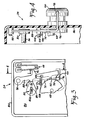
- FIG. 3 and 4 the feature of the invention is illustrated wherein, during the "KEEP WARM" mode of operation, an alarm bell is continuously cycled indicating that the appliance is operating in "KEEP WARM” mode.
- the programmer timer 24 is mounted in a housing or body 84 having a wall or mounting deck 86 apertured to receive drive shaft 56 therethrough.
- Sub-interval cam 80 is disposed adjacent the upper surface of the deck or the left hand side as shown in Figure 4.
- a moveable arm 88 is pivotally mounted at one end thereof about pin 90 which extends from the left hand or upper surface of the deck 86 and has an actuator portion 92 preferably formed integrally therewith, for contacting the blade of switch 48.
- Arm 88 has a cam follower 94 formed thereon for contact with the lobe on sub-interval cam 80.
- the free end of arm 88 is formed at right angles to the upper or left hand surface of the deck 86 and extends through an aperture 96 formed in the deck.
- the end of arm 88 which extends through aperture 96 has attached thereto a suitable striker of clapper 98 disposed for impact against an alarm bell 100 mounted on the lower or right hand side of the deck 86.
- Arm 88 also has cam follower 94 disposed intermediate the ends thereof.
- a second cam follower 102 is disposed intermediate the free end of arm 88 and cam follower 94.
- Shaft 68 and cam track 74 are disposed adjacent the upper or left hand face of deck 86 such that cam follower 102 on arm 88 is in a position for contacting cam track 74.
- sub-interval cam 80 is shown as contacting cam follower 94 in solid outline in the position of maximum lift by cam 80.
- Switch actuating portion 92 has closed switch 48 and striker 98 is lifted from contacting bell 100.
- arm 88 also prevents cam follower 102 on arm 88 from contacting cam track 74.
- a bias spring 104 has one end thereof anchored to a lug 106 provided on arm 88 and the other end anchored to a stationary lug 108 extending from the upper left hand face of deck 86.
- Spring 104thus biases arm 88 leftward in Figure 3 or in a direction to urge the cam follower 94 into contact with sub-interval cam 80 and cam follower 102 into contact with cam track 74.
- the drive shaft 56 has a lost motion connection indicated generally at 110 wherein shaft 56 has a key 82a provided thereon and preferably in theform of a double headed key.
- Cam lobe 80 has a slot 83 provided therein and configured to conform generally to the shape of the double headed key 82a. Slot 83 is configured so as to permit a desired amou nt of rotational movement of shaft 56 before causing rotational movement of cam lobe 80. This minor amount of rotational lost motion is operative to cause a snap-action of the cam 80 when follower 94 is in contact with the descending ramp of the cam lobe.
- cam drum shaft 68 In operation, upon the advance pawl 58 encountering the toothless space 66 on rachet wheel 62, rotation of the cam drum shaft 68 is terminated and cam track 70 maintains switch 40 closed.
- the timer motor 26 continues to run and to cycle cam lobe 80 for raising and lowering arm 88 thereby cycling magnetron switch 48 and the striker against bell 100. In the position shown in Figure 3, cam track 74 does not prevent the striker 98 from contacting bell 100.
- cam drum shaft 68 is manually advanced by the operator causing cam follower 76 to drop into the notch on cam track 70 for opening switch 40 to stop the timing motor.
- cam track 74 is operative to cause the lobe thereon to engage cam follower 102 on arm 88 thereby lifting the arm and permitting the lobe to pass by follower 100 and permitting the striker 98 to contact bell 102 to thereby signal the end of the "COOK" cycle. It will be understood that upon completion of the "COOK" cycle arm 88 is thereafter cycled by rotation of the sub-interval cam 80. Thus, cam track 74 must have a diameter sufficiently small to permit the follower 102 to drop without contacting the cam trackto thereby enable the striker 98 to contact bell 100.
- the present invention thus provides a novel control of an electrical appliance and particularly a microwave cooking oven, in a manner permitting the appliance to be pulsed for short duration "ON" time upon completion of the normal "COOK” mode of operation.
- the present inventtion permits the appliance to continue intermittent "KEEP WARM" mode of operation upon the conclusion of normal duty cycle.
- An audible warning that such intermittent operations is, in process is provided until such time as the operator manually advances the prog rammer cam drum to shut the power off to the appliance and programmer timer.
Landscapes
- Engineering & Computer Science (AREA)
- Chemical & Material Sciences (AREA)
- Physics & Mathematics (AREA)
- Power Engineering (AREA)
- Materials Engineering (AREA)
- Manufacturing & Machinery (AREA)
- Computer Hardware Design (AREA)
- Microelectronics & Electronic Packaging (AREA)
- Condensed Matter Physics & Semiconductors (AREA)
- General Physics & Mathematics (AREA)
- Crystallography & Structural Chemistry (AREA)
- Metallurgy (AREA)
- Organic Chemistry (AREA)
- Electromagnetism (AREA)
- Inorganic Chemistry (AREA)
- Electric Ovens (AREA)
- Food-Manufacturing Devices (AREA)
Claims (10)
Applications Claiming Priority (2)
| Application Number | Priority Date | Filing Date | Title |
|---|---|---|---|
| US495895 | 1983-05-18 | ||
| US06/495,895 US4616209A (en) | 1983-05-18 | 1983-05-18 | "Keep warm" control |
Publications (2)
| Publication Number | Publication Date |
|---|---|
| EP0128634A1 EP0128634A1 (de) | 1984-12-19 |
| EP0128634B1 true EP0128634B1 (de) | 1988-06-08 |
Family
ID=23970428
Family Applications (1)
| Application Number | Title | Priority Date | Filing Date |
|---|---|---|---|
| EP84300914A Expired EP0128634B1 (de) | 1983-05-18 | 1984-02-14 | Steuersystem für eine elektrische Vorrichtung |
Country Status (10)
| Country | Link |
|---|---|
| US (1) | US4616209A (de) |
| EP (1) | EP0128634B1 (de) |
| JP (1) | JPS59212908A (de) |
| KR (1) | KR850000085A (de) |
| AU (1) | AU575803B2 (de) |
| BR (1) | BR8401678A (de) |
| CA (1) | CA1208344A (de) |
| DE (1) | DE3472034D1 (de) |
| NZ (1) | NZ207143A (de) |
| SG (1) | SG90588G (de) |
Families Citing this family (10)
| Publication number | Priority date | Publication date | Assignee | Title |
|---|---|---|---|---|
| US5042311A (en) * | 1988-06-06 | 1991-08-27 | Eaton Corporation | Secondary timer for program timer |
| US5113124A (en) * | 1990-09-04 | 1992-05-12 | Eaton Corporation | Programmable appliance controller |
| US5322436A (en) * | 1992-10-26 | 1994-06-21 | Minnesota Mining And Manufacturing Company | Engraved orthodontic band |
| US5510585A (en) * | 1993-09-30 | 1996-04-23 | Eaton Corporation | Electromechanical programmer/timer |
| JP3216474B2 (ja) * | 1995-03-30 | 2001-10-09 | 株式会社日立製作所 | 走査型電子顕微鏡 |
| US5745441A (en) * | 1996-03-21 | 1998-04-28 | Maytag Corporation | Mechanical timer including cam operated clapper and chimes |
| US5736699A (en) * | 1996-05-03 | 1998-04-07 | Eaton Corporation | Elecro-mechanical programmer/timer |
| KR19990017174A (ko) * | 1997-08-21 | 1999-03-15 | 윤종용 | 전자렌지의 운전제어방법 |
| US6018290A (en) * | 1998-03-12 | 2000-01-25 | Emerson Electric Co. | Apparatus for permitting quiet manual setting of an appliance timer having a bell chime assembly associated therewith |
| US6150640A (en) * | 1999-09-04 | 2000-11-21 | Ya Horng Electronic Co., Ltd. | Temperature controller for electric cooking appliances |
Family Cites Families (11)
| Publication number | Priority date | Publication date | Assignee | Title |
|---|---|---|---|---|
| US3694591A (en) * | 1971-05-14 | 1972-09-26 | Mallory & Co Inc P R | Motor driven timer with cam operated buzzer construction |
| JPS5132195B2 (de) * | 1972-01-20 | 1976-09-10 | ||
| US3824365A (en) * | 1972-12-07 | 1974-07-16 | Litton Systems Inc | Microwave oven control system |
| GB1560500A (en) * | 1976-03-09 | 1980-02-06 | Matsushita Electric Ind Co Ltd | Microwave oven |
| US4133998A (en) * | 1976-06-22 | 1979-01-09 | Sharp Kabushiki Kaisha | Cooking mode selector for continuously varying a mean output level of a magnetron in a microwave oven |
| JPS536786A (en) * | 1976-07-07 | 1978-01-21 | Matsushita Electric Ind Co Ltd | Program control device |
| US4206337A (en) * | 1976-11-18 | 1980-06-03 | Robertshaw Controls Company | Microwave oven having improved defrost cycle timer means |
| US4153824A (en) * | 1977-10-19 | 1979-05-08 | Blackmond George O | Appliance control timer drive means |
| US4242746A (en) * | 1978-10-02 | 1980-12-30 | Emhart Industries, Inc. | Timing mechanism with two separate programs operating separate switch actuators and having an alarm system |
| US4467664A (en) * | 1981-09-28 | 1984-08-28 | The Singer Company | Timer drive mechanism |
| US4523062A (en) * | 1983-05-02 | 1985-06-11 | Eaton Corporation | Electrical appliance programming |
-
1983
- 1983-05-18 US US06/495,895 patent/US4616209A/en not_active Expired - Fee Related
-
1984
- 1984-02-08 CA CA000446984A patent/CA1208344A/en not_active Expired
- 1984-02-10 AU AU24459/84A patent/AU575803B2/en not_active Ceased
- 1984-02-14 DE DE8484300914T patent/DE3472034D1/de not_active Expired
- 1984-02-14 EP EP84300914A patent/EP0128634B1/de not_active Expired
- 1984-02-14 NZ NZ207143A patent/NZ207143A/en unknown
- 1984-03-02 JP JP59040245A patent/JPS59212908A/ja active Pending
- 1984-04-07 KR KR1019840001843A patent/KR850000085A/ko not_active Abandoned
- 1984-04-11 BR BR8401678A patent/BR8401678A/pt unknown
-
1988
- 1988-12-31 SG SG905/88A patent/SG90588G/en unknown
Also Published As
| Publication number | Publication date |
|---|---|
| SG90588G (en) | 1989-09-01 |
| BR8401678A (pt) | 1985-03-19 |
| AU575803B2 (en) | 1988-08-11 |
| JPS59212908A (ja) | 1984-12-01 |
| CA1208344A (en) | 1986-07-22 |
| AU2445984A (en) | 1984-11-22 |
| KR850000085A (ko) | 1985-02-25 |
| NZ207143A (en) | 1988-02-12 |
| DE3472034D1 (en) | 1988-07-14 |
| US4616209A (en) | 1986-10-07 |
| EP0128634A1 (de) | 1984-12-19 |
Similar Documents
| Publication | Publication Date | Title |
|---|---|---|
| CA1214829A (en) | Electrical appliance timing mechanism | |
| EP0128634B1 (de) | Steuersystem für eine elektrische Vorrichtung | |
| EP0661908B1 (de) | Bedienungsschalter eines Mikrowellenofens und Steuerschaltung hierzu | |
| CA1257367A (en) | Microwave oven timer | |
| US5290978A (en) | Programmer/timer with rapid advance | |
| CA1229639A (en) | Programmer/timer for appliances | |
| EP0168536B1 (de) | Kontrolle eines Gerätes und Zeitprogrammgeber dafür | |
| US2917988A (en) | Control device | |
| EP1058482A2 (de) | Mikrowellenofen | |
| KR100272367B1 (ko) | 전자레인지의 도어 개폐구조 | |
| CA1321226C (en) | Electrical programmer | |
| US4629845A (en) | Electrical appliance programming | |
| US5637843A (en) | Electromechanical programmer/timer | |
| US5828019A (en) | Motorized sequencing switch assembly | |
| US5736699A (en) | Elecro-mechanical programmer/timer | |
| US6018290A (en) | Apparatus for permitting quiet manual setting of an appliance timer having a bell chime assembly associated therewith | |
| KR0146599B1 (ko) | 전자렌지의 전자제어식 타이머 | |
| KR0146600B1 (ko) | 전자렌지의 전자제어식 타이머 | |
| WO2006078501A1 (en) | Appliance timer mechanism utilizing snap action switching | |
| KR930000697Y1 (ko) | 타이머 | |
| GB2178504A (en) | Washing machine safety lock | |
| KR200156216Y1 (ko) | 타임 스위치 | |
| JPH01139927A (ja) | 時限制御装置 | |
| JPS6351082A (ja) | 時限制御装置 | |
| GB1113558A (en) | Manual shaft driving means |
Legal Events
| Date | Code | Title | Description |
|---|---|---|---|
| PUAI | Public reference made under article 153(3) epc to a published international application that has entered the european phase |
Free format text: ORIGINAL CODE: 0009012 |
|
| AK | Designated contracting states |
Designated state(s): DE FR GB IT |
|
| 17P | Request for examination filed |
Effective date: 19841105 |
|
| 17Q | First examination report despatched |
Effective date: 19860117 |
|
| GRAA | (expected) grant |
Free format text: ORIGINAL CODE: 0009210 |
|
| AK | Designated contracting states |
Kind code of ref document: B1 Designated state(s): DE FR GB IT |
|
| ITF | It: translation for a ep patent filed | ||
| REF | Corresponds to: |
Ref document number: 3472034 Country of ref document: DE Date of ref document: 19880714 |
|
| ET | Fr: translation filed | ||
| PLBE | No opposition filed within time limit |
Free format text: ORIGINAL CODE: 0009261 |
|
| STAA | Information on the status of an ep patent application or granted ep patent |
Free format text: STATUS: NO OPPOSITION FILED WITHIN TIME LIMIT |
|
| 26N | No opposition filed | ||
| PGFP | Annual fee paid to national office [announced via postgrant information from national office to epo] |
Ref country code: FR Payment date: 19891210 Year of fee payment: 7 |
|
| PGFP | Annual fee paid to national office [announced via postgrant information from national office to epo] |
Ref country code: DE Payment date: 19891212 Year of fee payment: 7 |
|
| PGFP | Annual fee paid to national office [announced via postgrant information from national office to epo] |
Ref country code: GB Payment date: 19891231 Year of fee payment: 7 |
|
| ITTA | It: last paid annual fee | ||
| PG25 | Lapsed in a contracting state [announced via postgrant information from national office to epo] |
Ref country code: GB Effective date: 19910214 |
|
| GBPC | Gb: european patent ceased through non-payment of renewal fee | ||
| PG25 | Lapsed in a contracting state [announced via postgrant information from national office to epo] |
Ref country code: FR Effective date: 19911031 |
|
| PG25 | Lapsed in a contracting state [announced via postgrant information from national office to epo] |
Ref country code: DE Effective date: 19911101 |
|
| REG | Reference to a national code |
Ref country code: FR Ref legal event code: ST |