EP0127637B1 - Apparatus for trimming and emptying bulk material - Google Patents
Apparatus for trimming and emptying bulk material Download PDFInfo
- Publication number
- EP0127637B1 EP0127637B1 EP83903591A EP83903591A EP0127637B1 EP 0127637 B1 EP0127637 B1 EP 0127637B1 EP 83903591 A EP83903591 A EP 83903591A EP 83903591 A EP83903591 A EP 83903591A EP 0127637 B1 EP0127637 B1 EP 0127637B1
- Authority
- EP
- European Patent Office
- Prior art keywords
- lifting means
- ship
- trimming
- chassis
- rakes
- Prior art date
- Legal status (The legal status is an assumption and is not a legal conclusion. Google has not performed a legal analysis and makes no representation as to the accuracy of the status listed.)
- Expired
Links
Images


Classifications
-
- B—PERFORMING OPERATIONS; TRANSPORTING
- B63—SHIPS OR OTHER WATERBORNE VESSELS; RELATED EQUIPMENT
- B63B—SHIPS OR OTHER WATERBORNE VESSELS; EQUIPMENT FOR SHIPPING
- B63B27/00—Arrangement of ship-based loading or unloading equipment for cargo or passengers
- B63B27/22—Arrangement of ship-based loading or unloading equipment for cargo or passengers of conveyers, e.g. of endless-belt or screw-type
Definitions
- the present invention relates to an apparatus for trimming and emptying bulk material from a storage room or hold, comprising at least one rake means which is movable vertically and transversely of the direction of motion of the bulk material, and which is arranged to move a bulk material towards a lifting means.
- each hold has a fixed vertical transporter or lifting means which is fed with bulk material by two orthogonally arranged rake means. Since each hold must have fixed equipment, this system entails large expenditures for ships having a plurality of holds.
- the pick up head is a bucket elevator means that when it scoops up material to be unloaded it is moving the material in a direction away from, rather than towards, the main elevator. This means that it may have difficulties in removing the last rest of material from the cargo room.
- the bucket conveyor pick up head is not suitable for trimming cargo, i.e. spreading it out in the cargo room during loading.
- DE-A-2 144 637 shows a shipboard unloading device comprising a movable gantry-like structure supporting a rather complicated bucket elevator.
- This device has a very high centre of gravity, being detrimental to ship stability, and when not in use, it is difficult to park out of the way and protected from detrimental environmental effects, like salt water spray, icing etc.
- the purpose of the present invention is to provide a trimming and emptying apparatus for bulk material in a hold or storage chamber, of the kind disclosed by GB-A-2 070 556, and which does not suffer from the above drawbacks and deficiencies.
- This is obtained according to the invention by means of an apparatus for trimming and emptying bulk material in a cargo or storage room, comprising feeding means which is movable vertically and transversely of its feeding direction and is arranged to move the bulk material towards a lifting means, said lifting means being vertically movable, said feeding means being at one end pivotably attached near the lower end of the lifting means in a suspension device which is pivotable about a vertical axis, preferably together with the lifting means, characterized in that it comprises a chassis which runs along the top side of said room, that the lifting means is supported in a housing which is movable on the chassis generally transversely of the direction of motion of the chassis, and in that said feeding means comprises two feeding devices each constituted by a rake means arranged on opposite sides of the lifting means.
- the arrangement according to the invention cancels lateral reaction forces of the rakes acting at the lower end of the main elevator.
- the lifting means and the rakes are also movable together with the housing so that the rakes can be brought into less accessible parts of the holds, i.e. between webs and other reinforcements.
- the transverse movability of the rakes also entails that these may be made substantially shorter than half of the width of the room without sacrificing the ability of the system to completely empty the hold.
- the supporting means for the rakes are pivotable about a vertical axis, together with the lifting means, the rakes may reach all parts of the cargo room even though the hatchway of the latter does not extend in its entire length.
- the housing is provided with a vertically telescoping extension wherein the lifting means is suspended.
- the housing will not extend higher than necessary whether the apparatus is in use or in parked condition. In this way it is easier to avoid the housing blocking the view from the bridge and avoid unnecessary stress and strain on the apparatus during transit in rough seas.
- the invention also comprises a ship having one or more cargo rooms which in the top is provided with at least one hatchway surrounded by a coaming, wherein the ship also comprises a trimming and emptying apparatus according to the invention as previously stated.
- the coaming may be provided with rails on the outside on which the chassis of the apparatus may run, and the ship may also advantageously be provided with a parking space for the apparatus.
- This parking space may advantageously comprise a recess into which parts of the apparatus may be lowered when it is not in use. Thereby, the apparatus may be secured more easily when it is not in use, it will be less subjected to inertia forces when the ship moves in heavy sea, and it will be less likely to block the view from the bridge of the ship.
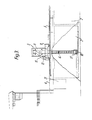
- the ship shown in Figs. 1 and 2 which generally is designated by 1, comprises a plurality of holds 2.
- the ship is provided with a trimming and emptying apparatus 3 according to the invention, for brevity called unloading apparatus, which is at work in the aft hold 2 of the ship.
- the unloading apparatus is in Fig. 1 shown in two alternative positions, one 3' during unloading of one of the other holds, and the other 3" in parked position close to the superstructure of the ship. It will be understood that the unloading apparatus is movable along rails 4 extending in the longitudinal direction of the ship.
- the ship is provided with a longitudinal belt conveyor 5 which is fed by the unloading apparatus 3, and which in turn feeds a pivotably supported belt conveyor 6 for landing the bulk material 7.
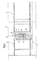
- the unloading apparatus comprises a chassis 8 which is drivable on rails 4.
- a housing 9 On the chassis a housing 9 is arranged which is movable over an opening 10 in the chassis in the transverse direction of the ship.
- a chute 11 From the housing 9 a chute 11 extends to a transverse belt conveyor 12 mounted on the chassis 8. The transverse belt conveyor feeds the longitudinal belt conveyor 5.
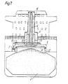
- Figs. 5-7 show further details of the unloading apparatus according to the invention. It will be seen that the housing 9 is provided with supports 13 for a telescoping extension 14 of the housing. This extension 14 is internally provided with a ⁇ hoisting means 15 for a lifting means for bulk material in the form of a bucket elevator. The housing is of course provided with guides (not shown) for the lifting means.
- the lifting means 16 is provided with a fork suspension 17 for two opposite rake means 18, 19.
- These rakes are attached to the fork suspension by one of their ends so that by means of suitable means (not shown) they can be pivoted between a generally vertical and a generally horizontal position, as suggested in Fig. 6.
- the rakes work towards each other as shown by the arrows on their bottom side, so that the reaction forces exerted on the fork suspension 17 are largely cancelled.
- Fig. 6 also shows the motion direction and possibilities for the various components comprised in the unloading apparatus according to the invention. It is also suggested that the lifting means 16 with the rakes 18, 19 may be pivoted about a vertical axis.
- Fig. 7 shows the lifting means 16 with the rakes 18, 19 in the upper position.
- the apparatus according to the invention may be driven from one hold to another without being hindered by the hatches 20.
- This condition also forms the starting point for the unloading.
- With the rakes in the upright position these are lowered together with the lifting means 16 down into the bulk material while they are driven in the usual way.
- the equipment is pressed down into the bulk material by means of its own weight, which, if necessary, may in increased by providing the lifting means 16 and/or the rakes 18, 19 with ballast tanks which may be filled with water.
- the free ends of the rakes clear the bottom side of the chassis 8, they may gradually be swung out to their most suitable position.
- the rakes may be swung independently of each other and thereby form different angles with the horizontal if this should be expedient.
- the chassis 8 and the housing 9 are driven in a pre-programmed pattern, so that the material is taken from both sides while the main movement proceeds in the longitudinal direction of the ship.
- the unloading is adjusted to the natural sliding angle of the material in order to use the least possible energy.
- Fig. 8 shows the unloading apparatus in an alternative position, the lifting means 16 with the rakes 18, 19 being pivoted 90° for the rakes to work in the longitudinal direction of the ship.
- This working position may be advantageous when the hatch coaming is relatively small with respect to the surface area of the hold.
- the pivotability of the rakes about a vertical axis is also of importance when they are used to trim the cargo in the hold. For this purpose the rakes are driven in the opposite direction so that they push the bulk material away from the middle of the hold towards its sides.
- the ship is provided with a recess 21 between the superstructure and the rear cargo room.
- This recess is used for parking the unloading apparatus as indicated by 3" in Fig. 1.
- the lifting means 1.6 with the rakes 18, 19 into the recess the housing extension 14 will come low enough in order not to block the view from the bridge. Furthermore, in this position the unloading apparatus will be relatively well protected and may be sufficiently supported.
- the rails 4 for the chassis 8 are arranged on the outside of the hatch coamings 22.
- the unloading apparatus may be driven from parking position to any of the holds without the necessity of removing any of the hatches 20 passed on the way.
- the ship can be provided with more than one unloading apparatus according to the invention if this should be expedient for reasons of unloading capacity. However, it is not necessary to store the unloading apparatus on board the ship when it is not in use. Instead it can be taken off the ship when unloading is finished for use with other ships.
- the apparatus may be provided with more than two rakes, i.a. four rakes working in two orthogonal directions.
- the lifting means being a bucket elevator in the example shown, may be replaced by any suitable lifting means, i.a. a screw conveyor, a suction device, a bucket wheel or the like, according to the properties of the material. If the hold is deep or it is desirable to make the housing for the lifting means lower, the lifting means may be divided into parts being vertically movable with respect to each other, the lower part delivering to the upper. With such a solution one can avoid having to use a telescoping extension of the housing.
- the pivotability of the rakes about a vertical axis which in the example shown is performed together with the lifting means, may alternatively take place independently of the pivoting of the lifting means.
- the apparatus may be installed in a very short time both in new and in existing ships without substantial modifications.
- the apparatus will be able to empty the holds almost completely so that use of other tools or machines becomes unnecessary during the final phases of the unloading.
- the apparatus can therefore work continuously and thereby save valuable unloading time. If the apparatus should be damaged when in use, it can be repaired on deck while the unloading may proceed with other means, for instance a grab.
- the unloading apparatus does not prevent the ship from other cargoes than bulk material.
Abstract
Description
- The present invention relates to an apparatus for trimming and emptying bulk material from a storage room or hold, comprising at least one rake means which is movable vertically and transversely of the direction of motion of the bulk material, and which is arranged to move a bulk material towards a lifting means.
- Such an apparatus is known i.a. from US-A-4 170 433. Here, each hold has a fixed vertical transporter or lifting means which is fed with bulk material by two orthogonally arranged rake means. Since each hold must have fixed equipment, this system entails large expenditures for ships having a plurality of holds.
- From US-A-4 350 467 a system of a somewhat different character is known. Here, one has a lifting means arranged in the forward part of a ship. This lifting means is fed by a belt conveyor which extends centrally near the bottom of all the holds. In order to move that part of the bulk material which will not slide by itself down towards the belt conveyor, one uses two rake means which may be raised and lowered in the hold and, furthermore, are pivotable about one end. These rakes may be moved from one hold to another by means of a carriage which can be driven in the longitudinal direction of the ship on the top side of the holds. In this case the rakes must be sufficiently long to reach the sides of the hold in order to completely empty the hold. For the same reason the hatchways of the holds must extend almost the entire length of the holds in order not to leave material by the transverse bulkheads separating the holds. However, the longitudinal conveyor at the bottom of the ship necessitates an open connection between all holds. This entails that such a system may not be used for oceangoing vessels, because for such vessels it is required that the holds be separated by means of watertight bulkheads.
- There is also known from GB-A-2 070 556 an apparatus in accordance with the preamble of claim 1, for trimming and emptying bulk material in a cargo or storage room, comprising feeding means which is movable vertically and transversely of its feeding direction and is arranged to move the bulk material towards a lifting means, said lifting means being vertically movable and pivotable about a vertical axis, said feeding means being at one end pivotably attached near the lower end of the lifting means.
- The fact that only one feeding means, namely a pick up head, is provided will give rise to unbalanced lateral forces that will subject the frames to considerable bending loads, thus necessitating the use of more material than otherwise necessary, thus increasing cost and weight, and causing friction which in turn increases energy consumption per unit cargo unloaded. The fact that the pick up head is a bucket elevator means that when it scoops up material to be unloaded it is moving the material in a direction away from, rather than towards, the main elevator. This means that it may have difficulties in removing the last rest of material from the cargo room. Furthermore, the bucket conveyor pick up head is not suitable for trimming cargo, i.e. spreading it out in the cargo room during loading.
- On the other hand, DE-A-2 144 637, shows a shipboard unloading device comprising a movable gantry-like structure supporting a rather complicated bucket elevator. This device has a very high centre of gravity, being detrimental to ship stability, and when not in use, it is difficult to park out of the way and protected from detrimental environmental effects, like salt water spray, icing etc.
- The purpose of the present invention is to provide a trimming and emptying apparatus for bulk material in a hold or storage chamber, of the kind disclosed by GB-A-2 070 556, and which does not suffer from the above drawbacks and deficiencies. This is obtained according to the invention by means of an apparatus for trimming and emptying bulk material in a cargo or storage room, comprising feeding means which is movable vertically and transversely of its feeding direction and is arranged to move the bulk material towards a lifting means, said lifting means being vertically movable, said feeding means being at one end pivotably attached near the lower end of the lifting means in a suspension device which is pivotable about a vertical axis, preferably together with the lifting means, characterized in that it comprises a chassis which runs along the top side of said room, that the lifting means is supported in a housing which is movable on the chassis generally transversely of the direction of motion of the chassis, and in that said feeding means comprises two feeding devices each constituted by a rake means arranged on opposite sides of the lifting means.
- Thus one obtains an apparatus which may be moved from one room to another, so that in case the ship has several cargo rooms, only one apparatus is necessary. Since no part of the unloading system remains permanently in any of the holds, these may be separated by means of watertight bulkheads so that the ship will fulfill the requirements for oceangoing vessels.
- Moreover, the arrangement according to the invention cancels lateral reaction forces of the rakes acting at the lower end of the main elevator.
- Since the housing is movable on the chassis generally transversely of the direction of motion of the chassis, the lifting means and the rakes are also movable together with the housing so that the rakes can be brought into less accessible parts of the holds, i.e. between webs and other reinforcements. The transverse movability of the rakes also entails that these may be made substantially shorter than half of the width of the room without sacrificing the ability of the system to completely empty the hold.
- Since the supporting means for the rakes are pivotable about a vertical axis, together with the lifting means, the rakes may reach all parts of the cargo room even though the hatchway of the latter does not extend in its entire length.
- According to a preferred embodiment of the invention, the housing is provided with a vertically telescoping extension wherein the lifting means is suspended. Thus, the housing will not extend higher than necessary whether the apparatus is in use or in parked condition. In this way it is easier to avoid the housing blocking the view from the bridge and avoid unnecessary stress and strain on the apparatus during transit in rough seas.
- The invention also comprises a ship having one or more cargo rooms which in the top is provided with at least one hatchway surrounded by a coaming, wherein the ship also comprises a trimming and emptying apparatus according to the invention as previously stated. The coaming may be provided with rails on the outside on which the chassis of the apparatus may run, and the ship may also advantageously be provided with a parking space for the apparatus. This parking space may advantageously comprise a recess into which parts of the apparatus may be lowered when it is not in use. Thereby, the apparatus may be secured more easily when it is not in use, it will be less subjected to inertia forces when the ship moves in heavy sea, and it will be less likely to block the view from the bridge of the ship.
- For the better understanding of the invention it will be described more closely with reference to the exemplifying embodiment shown in the appended drawings.
- Fig. 1 shows a side view, partly in section, of a ship provided with an apparatus according to the invention.
- Fig. 2 shows the ship of Fig. 1 in plan view.
- Fig. 3 shows a part of Fig. 1 at a larger scale.
- Fig. 4 shows a part of Fig. 2 at a larger scale.
- Fig. 5 generally shows a section along the line V-V in Fig. 1 at a larger scale.
- Fig. 6 shows a section like Fig. 5, but with an empty cargo room.
- Fig. 7 shows a section like Figs. 5 and 6, but with the cargo room full.
- The ship shown in Figs. 1 and 2, which generally is designated by 1, comprises a plurality of
holds 2. The ship is provided with a trimming and emptying apparatus 3 according to the invention, for brevity called unloading apparatus, which is at work in the aft hold 2 of the ship. The unloading apparatus is in Fig. 1 shown in two alternative positions, one 3' during unloading of one of the other holds, and the other 3" in parked position close to the superstructure of the ship. It will be understood that the unloading apparatus is movable along rails 4 extending in the longitudinal direction of the ship. Furthermore, the ship is provided with alongitudinal belt conveyor 5 which is fed by the unloading apparatus 3, and which in turn feeds a pivotably supported belt conveyor 6 for landing the bulk material 7. - From Figs. 3 and 4, which are parts of Figs. 1 and 2 at a larger scale, it will be evident that the unloading apparatus according to the invention comprises a
chassis 8 which is drivable on rails 4. On the chassis ahousing 9 is arranged which is movable over an opening 10 in the chassis in the transverse direction of the ship. From the housing 9 achute 11 extends to atransverse belt conveyor 12 mounted on thechassis 8. The transverse belt conveyor feeds thelongitudinal belt conveyor 5. - Figs. 5-7 show further details of the unloading apparatus according to the invention. It will be seen that the
housing 9 is provided withsupports 13 for atelescoping extension 14 of the housing. Thisextension 14 is internally provided with a · hoisting means 15 for a lifting means for bulk material in the form of a bucket elevator. The housing is of course provided with guides (not shown) for the lifting means. - At the bottom the lifting means 16 is provided with a
fork suspension 17 for two opposite rake means 18, 19. These rakes are attached to the fork suspension by one of their ends so that by means of suitable means (not shown) they can be pivoted between a generally vertical and a generally horizontal position, as suggested in Fig. 6. The rakes work towards each other as shown by the arrows on their bottom side, so that the reaction forces exerted on thefork suspension 17 are largely cancelled. Fig. 6 also shows the motion direction and possibilities for the various components comprised in the unloading apparatus according to the invention. It is also suggested that the lifting means 16 with therakes housing 9 in the transverse direction and the movability of thechassis 8 in the longitudinal direction of the ship (transversely of the drawing plane) make it possible for the rakes to reach the corners and other less accessible places in order to completely empty the hold. - Fig. 7 shows the lifting means 16 with the
rakes hatches 20. This condition also forms the starting point for the unloading. With the rakes in the upright position these are lowered together with the lifting means 16 down into the bulk material while they are driven in the usual way. The equipment is pressed down into the bulk material by means of its own weight, which, if necessary, may in increased by providing the lifting means 16 and/or therakes chassis 8, they may gradually be swung out to their most suitable position. It will be understood that the rakes may be swung independently of each other and thereby form different angles with the horizontal if this should be expedient. When the rakes have reached such a position that they can work fully, thechassis 8 and thehousing 9 are driven in a pre-programmed pattern, so that the material is taken from both sides while the main movement proceeds in the longitudinal direction of the ship. The unloading is adjusted to the natural sliding angle of the material in order to use the least possible energy. - Fig. 8 shows the unloading apparatus in an alternative position, the lifting means 16 with the
rakes - As shown i.a. in Figs. 1-4, the ship is provided with a recess 21 between the superstructure and the rear cargo room. This recess is used for parking the unloading apparatus as indicated by 3" in Fig. 1. By lowering the lifting means 1.6 with the
rakes housing extension 14 will come low enough in order not to block the view from the bridge. Furthermore, in this position the unloading apparatus will be relatively well protected and may be sufficiently supported. - It will be seen that the rails 4 for the
chassis 8 are arranged on the outside of thehatch coamings 22. Thus, the unloading apparatus may be driven from parking position to any of the holds without the necessity of removing any of thehatches 20 passed on the way. It will also be understood that the ship can be provided with more than one unloading apparatus according to the invention if this should be expedient for reasons of unloading capacity. However, it is not necessary to store the unloading apparatus on board the ship when it is not in use. Instead it can be taken off the ship when unloading is finished for use with other ships. - It will be understood that the invention may be modified and varied in a number of ways within the scope of the following claims. Thus, the apparatus may be provided with more than two rakes, i.a. four rakes working in two orthogonal directions. The lifting means, being a bucket elevator in the example shown, may be replaced by any suitable lifting means, i.a. a screw conveyor, a suction device, a bucket wheel or the like, according to the properties of the material. If the hold is deep or it is desirable to make the housing for the lifting means lower, the lifting means may be divided into parts being vertically movable with respect to each other, the lower part delivering to the upper. With such a solution one can avoid having to use a telescoping extension of the housing. The pivotability of the rakes about a vertical axis, which in the example shown is performed together with the lifting means, may alternatively take place independently of the pivoting of the lifting means.
- From the preceding description it will be clear that according to the invention a trimming and emptying apparatus for bulk material has been provided having very high flexibility and a number of advantages. Thus, the apparatus may be installed in a very short time both in new and in existing ships without substantial modifications. The apparatus will be able to empty the holds almost completely so that use of other tools or machines becomes unnecessary during the final phases of the unloading. The apparatus can therefore work continuously and thereby save valuable unloading time. If the apparatus should be damaged when in use, it can be repaired on deck while the unloading may proceed with other means, for instance a grab. Furthermore, the unloading apparatus does not prevent the ship from other cargoes than bulk material.
Claims (6)
Applications Claiming Priority (2)
| Application Number | Priority Date | Filing Date | Title |
|---|---|---|---|
| NO824032 | 1982-12-01 | ||
| NO824032A NO151404C (en) | 1982-12-01 | 1982-12-01 | LIFTING AND TRIMMING DEVICE FOR SHIPPING GOODS |
Publications (2)
| Publication Number | Publication Date |
|---|---|
| EP0127637A1 EP0127637A1 (en) | 1984-12-12 |
| EP0127637B1 true EP0127637B1 (en) | 1987-06-10 |
Family
ID=19886830
Family Applications (1)
| Application Number | Title | Priority Date | Filing Date |
|---|---|---|---|
| EP83903591A Expired EP0127637B1 (en) | 1982-12-01 | 1983-11-28 | Apparatus for trimming and emptying bulk material |
Country Status (10)
| Country | Link |
|---|---|
| US (1) | US4784560A (en) |
| EP (1) | EP0127637B1 (en) |
| JP (1) | JPS60500050A (en) |
| AU (1) | AU550799B2 (en) |
| DE (1) | DE3371977D1 (en) |
| DK (1) | DK157533C (en) |
| ES (1) | ES8503616A1 (en) |
| FI (1) | FI842938A (en) |
| NO (1) | NO151404C (en) |
| WO (1) | WO1984002112A1 (en) |
Families Citing this family (10)
| Publication number | Priority date | Publication date | Assignee | Title |
|---|---|---|---|---|
| JP2514212B2 (en) * | 1987-08-18 | 1996-07-10 | 住友重機械工業株式会社 | Unloader |
| NO891741L (en) * | 1989-04-26 | 1990-10-29 | Walter Nilsen | BULK MATERIAL LOADING SYSTEM. |
| US5348435A (en) * | 1991-07-08 | 1994-09-20 | Dms, Inc. | Bin unloading apparatus |
| GB9203536D0 (en) * | 1992-02-19 | 1992-04-08 | Strachan & Henshaw Ltd | Discharging bulk materials |
| FI98U1 (en) * | 1992-02-21 | 1992-04-28 | Ficote Oy | Foer ett siloliknande utrymme avsedd fraon ovansidan arbetande torvavlastare |
| US6010295A (en) * | 1998-03-19 | 2000-01-04 | Semisub Transshippers Inc. | Floating structure for the transfer of cargo |
| KR101167121B1 (en) | 2009-04-27 | 2012-07-20 | 현대제철 주식회사 | Apparatus for providing material |
| DE102011013329A1 (en) * | 2011-03-08 | 2012-09-13 | Roentdek-Handels Gmbh | pumped storage power plant |
| JP5824724B2 (en) * | 2012-03-02 | 2015-11-25 | 株式会社 商船三井 | Bulk cargo ship and bulk cargo ship handling method |
| US10968058B2 (en) * | 2017-07-31 | 2021-04-06 | Luis Sucre | U reclaimer utility device apparatus |
Citations (4)
| Publication number | Priority date | Publication date | Assignee | Title |
|---|---|---|---|---|
| US739760A (en) * | 1903-06-24 | 1903-09-22 | Carel C Vermeer | Apparatus for storing adn unloading materials. |
| DE2144637B2 (en) * | 1971-09-07 | 1975-02-27 | O & K Orenstein & Koppel Ag, 2400 Luebeck | Ship's own conveyor system |
| DE2628593A1 (en) * | 1975-06-26 | 1977-01-13 | Buehler Ag Geb | MOUNTING FOOT FOR SHIP UNLOADING SYSTEM |
| EP0055879A1 (en) * | 1980-12-29 | 1982-07-14 | Cornelis Spaans | Conveyor consisting of a cable having entraining members |
Family Cites Families (14)
| Publication number | Priority date | Publication date | Assignee | Title |
|---|---|---|---|---|
| US1058306A (en) * | 1912-02-29 | 1913-04-08 | Frederick H Kindl | Unloading apparatus. |
| US1584442A (en) * | 1925-09-30 | 1926-05-11 | Gaines O B Every | Cargo trimmer |
| US3144142A (en) * | 1962-10-01 | 1964-08-11 | Wallace Systems Inc W J | Self-unloading cargo ship |
| DE1208213B (en) * | 1964-02-04 | 1965-12-30 | Orenstein & Koppel Ag | Ship's own conveyor system |
| DE1262859B (en) * | 1964-02-17 | 1968-03-07 | Polysius S A R L | Device for the production of sausage-like moldings from cement raw material |
| US3497054A (en) * | 1967-09-05 | 1970-02-24 | Jack P Van Kleunen | Barge unloading system |
| US3857499A (en) * | 1973-10-31 | 1974-12-31 | Union Oil Co | Cargo handling equipment |
| JPS5522485Y2 (en) * | 1975-07-31 | 1980-05-29 | ||
| AU520761B2 (en) * | 1977-07-26 | 1982-02-25 | Mitsui Miike Seisakusho, K.K. | Conveying material vertically between two belts |
| SE419737C (en) * | 1978-04-12 | 1984-04-09 | Siwertell Ab | DEVICE FOR DISPOSAL OF BULK MATERIAL FROM A STORAGE SPACE |
| FI800631A (en) * | 1980-02-29 | 1981-08-30 | Kone Oy | KONTINUERLIG AVLASTNINGSANORDNING FOER MASSAMATERIAL |
| US4350467A (en) * | 1980-07-18 | 1982-09-21 | Paul Soros | Self-unloading cargo vessel |
| NO147376C (en) * | 1981-01-05 | 1984-07-03 | Norsk Hydro As | SHIPPING AND HANDLING EQUIPMENT FOR BULKGODS |
| JPS60197394A (en) * | 1984-03-15 | 1985-10-05 | 日本たばこ産業株式会社 | Knife grinder for rotary drum type cutter |
-
1982
- 1982-12-01 NO NO824032A patent/NO151404C/en unknown
-
1983
- 1983-11-28 AU AU22691/83A patent/AU550799B2/en not_active Ceased
- 1983-11-28 EP EP83903591A patent/EP0127637B1/en not_active Expired
- 1983-11-28 WO PCT/NO1983/000052 patent/WO1984002112A1/en active IP Right Grant
- 1983-11-28 DE DE8383903591T patent/DE3371977D1/en not_active Expired
- 1983-11-28 JP JP58503768A patent/JPS60500050A/en active Pending
- 1983-11-30 ES ES527682A patent/ES8503616A1/en not_active Expired
-
1984
- 1984-07-23 FI FI842938A patent/FI842938A/en not_active Application Discontinuation
- 1984-07-31 DK DK371484A patent/DK157533C/en not_active IP Right Cessation
-
1987
- 1987-04-03 US US07/035,279 patent/US4784560A/en not_active Expired - Fee Related
Patent Citations (4)
| Publication number | Priority date | Publication date | Assignee | Title |
|---|---|---|---|---|
| US739760A (en) * | 1903-06-24 | 1903-09-22 | Carel C Vermeer | Apparatus for storing adn unloading materials. |
| DE2144637B2 (en) * | 1971-09-07 | 1975-02-27 | O & K Orenstein & Koppel Ag, 2400 Luebeck | Ship's own conveyor system |
| DE2628593A1 (en) * | 1975-06-26 | 1977-01-13 | Buehler Ag Geb | MOUNTING FOOT FOR SHIP UNLOADING SYSTEM |
| EP0055879A1 (en) * | 1980-12-29 | 1982-07-14 | Cornelis Spaans | Conveyor consisting of a cable having entraining members |
Also Published As
| Publication number | Publication date |
|---|---|
| DK371484D0 (en) | 1984-07-31 |
| FI842938A0 (en) | 1984-07-23 |
| DE3371977D1 (en) | 1987-07-16 |
| NO151404B (en) | 1984-12-27 |
| AU2269183A (en) | 1984-06-18 |
| DK157533B (en) | 1990-01-22 |
| WO1984002112A1 (en) | 1984-06-07 |
| EP0127637A1 (en) | 1984-12-12 |
| ES527682A0 (en) | 1985-03-16 |
| NO824032L (en) | 1984-06-04 |
| JPS60500050A (en) | 1985-01-17 |
| ES8503616A1 (en) | 1985-03-16 |
| US4784560A (en) | 1988-11-15 |
| DK157533C (en) | 1990-07-16 |
| AU550799B2 (en) | 1986-04-10 |
| NO151404C (en) | 1985-04-10 |
| FI842938A (en) | 1984-07-23 |
| DK371484A (en) | 1984-07-31 |
Similar Documents
| Publication | Publication Date | Title |
|---|---|---|
| US7708514B2 (en) | Automated shipboard material handling and storage system | |
| US2988036A (en) | Barge cargo ship | |
| US4043285A (en) | Container ship | |
| KR960016210B1 (en) | Ship weight cargo loading and unloading system | |
| US4106641A (en) | Universal gantry crane | |
| US3687309A (en) | Device for transloading floating containers | |
| US3591023A (en) | Mechanically programmable marine transport cargo handling and stowage system | |
| EP0127637B1 (en) | Apparatus for trimming and emptying bulk material | |
| US2568330A (en) | Extensible ramp for ships | |
| US4568232A (en) | Barge mounted horizontal boom bulk unloader | |
| US4498584A (en) | Stackable container for use in a containerization system | |
| US5028194A (en) | Marine crane improvement | |
| CN101112944B (en) | Floating type ship unloading equipment | |
| CN1226865A (en) | Container handling means for container ship | |
| US4483655A (en) | Vessel loading method | |
| US3889621A (en) | Anchor handling vessel | |
| US6789493B2 (en) | Method and arrangement for shipping reels; tweendeck and tweendeck arrangement in cargo space of ship | |
| CA1045469A (en) | Ship carrying containers and the like | |
| EP1135290B1 (en) | Lifeboat system | |
| US4067284A (en) | Barge-carrying ship | |
| FI80416B (en) | FARTYG OCH DESS LASTNINGS- OCH LOSSNINGSSYSTEM. | |
| CN201056432Y (en) | Floating type vessel removing device | |
| CA1258651A (en) | Apparatus for trimming and emptying bulk material | |
| RU121228U1 (en) | FLOATER-LOADER | |
| US3504650A (en) | Cargo ships |
Legal Events
| Date | Code | Title | Description |
|---|---|---|---|
| PUAI | Public reference made under article 153(3) epc to a published international application that has entered the european phase |
Free format text: ORIGINAL CODE: 0009012 |
|
| AK | Designated contracting states |
Designated state(s): DE FR GB NL SE |
|
| 17P | Request for examination filed |
Effective date: 19841016 |
|
| GRAA | (expected) grant |
Free format text: ORIGINAL CODE: 0009210 |
|
| AK | Designated contracting states |
Kind code of ref document: B1 Designated state(s): DE FR GB NL SE |
|
| REF | Corresponds to: |
Ref document number: 3371977 Country of ref document: DE Date of ref document: 19870716 |
|
| ET | Fr: translation filed | ||
| PLBE | No opposition filed within time limit |
Free format text: ORIGINAL CODE: 0009261 |
|
| STAA | Information on the status of an ep patent application or granted ep patent |
Free format text: STATUS: NO OPPOSITION FILED WITHIN TIME LIMIT |
|
| 26N | No opposition filed | ||
| PGFP | Annual fee paid to national office [announced via postgrant information from national office to epo] |
Ref country code: FR Payment date: 19921119 Year of fee payment: 10 |
|
| PGFP | Annual fee paid to national office [announced via postgrant information from national office to epo] |
Ref country code: NL Payment date: 19921130 Year of fee payment: 10 |
|
| PG25 | Lapsed in a contracting state [announced via postgrant information from national office to epo] |
Ref country code: NL Effective date: 19940601 |
|
| NLV4 | Nl: lapsed or anulled due to non-payment of the annual fee | ||
| PG25 | Lapsed in a contracting state [announced via postgrant information from national office to epo] |
Ref country code: FR Effective date: 19940729 |
|
| REG | Reference to a national code |
Ref country code: FR Ref legal event code: ST |
|
| EAL | Se: european patent in force in sweden |
Ref document number: 83903591.2 |
|
| PGFP | Annual fee paid to national office [announced via postgrant information from national office to epo] |
Ref country code: DE Payment date: 19981105 Year of fee payment: 16 |
|
| PGFP | Annual fee paid to national office [announced via postgrant information from national office to epo] |
Ref country code: GB Payment date: 19981123 Year of fee payment: 16 |
|
| PGFP | Annual fee paid to national office [announced via postgrant information from national office to epo] |
Ref country code: SE Payment date: 19981127 Year of fee payment: 16 |
|
| PG25 | Lapsed in a contracting state [announced via postgrant information from national office to epo] |
Ref country code: GB Free format text: LAPSE BECAUSE OF NON-PAYMENT OF DUE FEES Effective date: 19991128 |
|
| PG25 | Lapsed in a contracting state [announced via postgrant information from national office to epo] |
Ref country code: SE Free format text: LAPSE BECAUSE OF NON-PAYMENT OF DUE FEES Effective date: 19991129 |
|
| EUG | Se: european patent has lapsed |
Ref document number: 83903591.2 |
|
| GBPC | Gb: european patent ceased through non-payment of renewal fee |
Effective date: 19991128 |
|
| PG25 | Lapsed in a contracting state [announced via postgrant information from national office to epo] |
Ref country code: DE Free format text: LAPSE BECAUSE OF NON-PAYMENT OF DUE FEES Effective date: 20000901 |