EP0127498B1 - Procédé de réglage automatique de la teneur en bore soluble de l'eau de refroidissement d'un réacteur nucléaire à eau sous pression - Google Patents
Procédé de réglage automatique de la teneur en bore soluble de l'eau de refroidissement d'un réacteur nucléaire à eau sous pression Download PDFInfo
- Publication number
- EP0127498B1 EP0127498B1 EP84400812A EP84400812A EP0127498B1 EP 0127498 B1 EP0127498 B1 EP 0127498B1 EP 84400812 A EP84400812 A EP 84400812A EP 84400812 A EP84400812 A EP 84400812A EP 0127498 B1 EP0127498 B1 EP 0127498B1
- Authority
- EP
- European Patent Office
- Prior art keywords
- dilution
- boration
- group
- zone
- reactor
- Prior art date
- Legal status (The legal status is an assumption and is not a legal conclusion. Google has not performed a legal analysis and makes no representation as to the accuracy of the status listed.)
- Expired
Links
Images

Classifications
-
- G—PHYSICS
- G21—NUCLEAR PHYSICS; NUCLEAR ENGINEERING
- G21C—NUCLEAR REACTORS
- G21C7/00—Control of nuclear reaction
- G21C7/06—Control of nuclear reaction by application of neutron-absorbing material, i.e. material with absorption cross-section very much in excess of reflection cross-section
- G21C7/08—Control of nuclear reaction by application of neutron-absorbing material, i.e. material with absorption cross-section very much in excess of reflection cross-section by displacement of solid control elements, e.g. control rods
-
- G—PHYSICS
- G21—NUCLEAR PHYSICS; NUCLEAR ENGINEERING
- G21C—NUCLEAR REACTORS
- G21C7/00—Control of nuclear reaction
- G21C7/06—Control of nuclear reaction by application of neutron-absorbing material, i.e. material with absorption cross-section very much in excess of reflection cross-section
- G21C7/22—Control of nuclear reaction by application of neutron-absorbing material, i.e. material with absorption cross-section very much in excess of reflection cross-section by displacement of a fluid or fluent neutron-absorbing material, e.g. by adding neutron-absorbing material to the coolant
-
- G—PHYSICS
- G21—NUCLEAR PHYSICS; NUCLEAR ENGINEERING
- G21D—NUCLEAR POWER PLANT
- G21D3/00—Control of nuclear power plant
- G21D3/08—Regulation of any parameters in the plant
- G21D3/12—Regulation of any parameters in the plant by adjustment of the reactor in response only to changes in engine demand
- G21D3/16—Varying reactivity
-
- Y—GENERAL TAGGING OF NEW TECHNOLOGICAL DEVELOPMENTS; GENERAL TAGGING OF CROSS-SECTIONAL TECHNOLOGIES SPANNING OVER SEVERAL SECTIONS OF THE IPC; TECHNICAL SUBJECTS COVERED BY FORMER USPC CROSS-REFERENCE ART COLLECTIONS [XRACs] AND DIGESTS
- Y02—TECHNOLOGIES OR APPLICATIONS FOR MITIGATION OR ADAPTATION AGAINST CLIMATE CHANGE
- Y02E—REDUCTION OF GREENHOUSE GAS [GHG] EMISSIONS, RELATED TO ENERGY GENERATION, TRANSMISSION OR DISTRIBUTION
- Y02E30/00—Energy generation of nuclear origin
- Y02E30/30—Nuclear fission reactors
Definitions
- the invention relates to a method for automatically adjusting the soluble boron content of the cooling water of a pressurized water nuclear reactor.
- Pressurized water nuclear reactors comprise a core constituted by assemblies arranged vertically and side by side in a tank containing pressurized water ensuring the cooling of the core and the transport of the heat from this core to the steam generators.
- the steam supplied by the steam generators makes it possible to drive a turbine which itself drives a turbo-alternator producing electric current.
- the operation of the reactor is generally ensured by the displacement in the vertical direction, inside the core, of control rods absorbing the neutrons.
- the movement of a regulating group made up of highly absorbent bars is automatically controlled using the difference between the actual average temperature as an adjustment parameter. of the core and a reference temperature which is a linear function of the power which the nuclear reactor must supply to the turbine.
- This additional means consists of a system for borification and dilution of the reactor cooling water, that is to say a set of means making it possible to vary the soluble boron content of the reactor cooling water.
- nuclear which can be introduced in the form of boric acid or, on the contrary, diluted by the introduction of pure water.
- the increase in the concentration of soluble boron in fact makes it possible to increase the absorption of neutrons by the cooling fluid and therefore to decrease the power of the recator. Dilution obviously has the opposite effect.
- the borification and dilution system of the reactor cooling water makes it possible to complete the action of the groups of control rods and in particular to correct the long-term effects due to variations in reactivity of the reactor.
- These long-term effects accompanying variations in the reactivity of the reactor include in particular the formation and disappearance of xenon by nuclear reaction in the reactor core.
- the appearance and transformation of xenon themselves have important effects on reactivity and on the axial distribution of power in the reactor core.
- the axial power distribution in the reactor core that is to say the power distribution in the vertical direction, is in fact neither homogeneous nor constant for various reasons, the main ones being that the control rods used for the reactor lines are generally inserted over part of the height of the core only, that this insertion is variable over time and that the density of the cooling water and the concentration of xenon in the core of the reactor are not constant according to its height.
- One of the aims sought during the operation of the reactor is to prevent the power distribution in the core from being too unbalanced between the upper part and the lower part of the heart.
- axial power imbalance ⁇ I a parameter representative of the power imbalance in the heart, called “axial power imbalance ⁇ I "and defined as follows: where P H is the power in the upper half of the core, P B the power in the lower half of the core and is the axial power imbalance expressed in% of the nominal power.
- the deviation of the value of the measured axial imbalance from a reference power axial imbalance ⁇ I ref which corresponds to the value of the ⁇ I measured at 100% of the reactor power is determined, the control rods being almost extracted and the xenon being in equilibrium throughout the core of the reactor.
- control rods comprising in particular the displacement of a regulation group as a function of the difference in the temperature of the core with respect to a reference temperature
- the boron content of the cooling water in order to be able to comply with the instructions for positioning the control rods as a function of the power level of the reactor. These positioning instructions are established so as to maintain the deviation of the power imbalance from the reference imbalance in a zone of small amplitude surrounding the zero value.
- the means of borication and the means of dilution are controlled manually by an operator. This partially manual driving mode can be considered relatively satisfactory if the power plant is used at a constant power level or with very slow variations in power levels.
- Such an automatic adjustment system is however complex since it requires the continuous determination of the boron concentration of the cooling fluid and the establishment of a correlation between the value of the desirable concentration and the value of different parameters of conduct of the reactor.
- the object of the invention is therefore to propose a method for automatic adjustment of the soluble boron content of the cooling water of a pressurized water nuclear reactor the conduct of which is ensured by the displacement in the vertical direction of bars control system absorbing neutrons in the reactor core consisting of assemblies arranged vertically and side by side and by adjusting the soluble boron content of the water under pressure by means of borication and means for diluting this water, the control rods comprising at least one regulating group consisting of highly absorbent rods which are moved automatically as a function of the difference between the average temperature of the core and a reference temperature as a function of the power which the reactor must supply and means being associated with the reactor for determining the axial power imbalance in the core and the deviation of this axial imbalance with respect to u n reference imbalance corresponding to the minimum insertion of the control rods in the core and to the balance of the xenon concentration in this core, this adjustment process being able to act in a safe manner according to a simple principle, to assist the group of regulation and allow
- FIG. 1 is a diagram giving the shape of the domains corresponding to borication and to dilution as a function of the difference between the axial power imbalance and the reference axial imbalance in the core of a nuclear reactor and of the position d '' a regulation group composed of highly absorbent control rods.
- the mode of piloting the reactor is that described in French patent FR-A-2 395 572.
- a first set of groups of lightened control bars in anti-reactivity is used which is moved according to the power required by the turbine at nuclear reactor and only according to this power.
- a regulation group R distinct from the preceding groups and consisting of highly absorbent bars is also moved in the reactor core to effect temperature regulation of the latter.
- This regulation group R is moved as a function of the difference between the real average temperature of the core and a reference temperature which is a linear function of the power demanded by the turbine.
- the real average temperature of the core is determined from the measurement of the temperature of the water in the primary circuit in the hot branch and in the cold branch of this circuit.
- the regulation group R is effectively moved in one direction or another only if the difference ⁇ T between the actual temperature and the reference temperature exceeds in absolute value a certain value corresponding to the half-width of the dead band of displacement of the regulatory group.
- the positions of the group R have been represented corresponding to the maximum insertion of this group into the heart and its maximum extraction, that is to say at the lowest position and at the highest position of the regulating group.
- the parameter representing the position of group R has been plotted on the ordinate and the second adjustment parameter, namely the difference between the axial power imbalance and the reference axial imbalance has been plotted on the abscissa.
- the characteristic parameter of the position of the group R was chosen as the number of steps to be taken in the direction of extraction to bring the group into its position, starting from the maximum insertion position.
- Figure 1 shows very schematically how are determined the zones of borication and dilution separated by a neutral zone which corresponds to the zone of maneuver of group R without intervention of the means of borication or dilution.
- This maneuvering zone has two distinct parts depending on the value of the deviation of the axial power imbalance from the reference imbalance.
- the maneuvering area of group R is only limited by the insertion limit at its part lower and by the extraction limit at its upper part.
- X and Y are determined according to the operating conditions of the nuclear reactor. These values are chosen in particular so as to be able to control the deviation of the axial power imbalance from the reference imbalance in a sufficiently strict manner, avoiding too frequent use of the borication and dilution system, in particular during Reciprocating movements of the power regulation groups (called gray groups) and of the temperature regulation group or group R.
- Y will be chosen less than 5%.
- the regulation group R is only allowed to move at the top of the core, between its limit extraction position and a lower position such as the area of maneuver widens when ⁇ I moves away from ⁇ I ref.
- a value will be chosen for the width of the neutral zone which is a function of the efficiency of the borication and dilution system and of the regulation group R.
- a dilution zone 2 and a borication zone 3 are defined, bounded on the right and on the left by two lines parallel to the ordinate axis whose abscissae depend on the power level of the reactor. r.
- the power regulation groups or gray groups have a position which depends only on the power level requested from the reactor.
- a reference temperature which is compared to the real average temperature of the core determined from temperature measurements in the hot branch and in the cold branch of the primary circuit. The difference ⁇ T between the average temperature and the reference temperature makes it possible to move the regulation group R if 4T is greater than the width of the dead band of this group R.
- the automatic action on the dilution or borication means results from the comparison of the pair of values corresponding to the position extracted from the group R and to the deviation of axial power imbalance with the pairs of values corresponding to each of the zones 1, 2 and 3 shown in FIG. 1 and corresponding respectively to the neutral zone, the dilution zone and the borication zone.
- control of the dilution or borication means is therefore done independently of the control of the regulation group R.
- the presence of the operating point in the neutral zone 1 causes the dilution or borication means to stop if either of these means were in operation previously. This corresponds to a transition from the operating point of zone 2 or of zone 3 to zone 1. If the means "of borication or dilution were not in operation, these means remain at a standstill and this corresponds to maintaining the operating point in zone 1.
- the passage of the operating point from one zone to another may correspond to an arrival of group R at one of its effective displacement limits, if the position of group R defining one of the two adjustment parameters is the actual instantaneous position of group R.
- a measurement of the axial power imbalance is carried out by neutron measurements at different heights in the core and the deviation of this axial imbalance from the reference imbalance is calculated.
- the second adjustment parameter namely the position of the regulation group R in the core
- a signal proportional to the temperature difference at T, borication or dilution can be triggered independently of the arrival of group R at one of its displacement terminals.
- each temperature signal ⁇ T can make a displacement of the group R correspond by a certain proportionality factor
- this fictitious position of the group R as the value of one of the two adjustment parameters, it is possible to trigger a dilution or borication action (or a stop of the dilution or a stop of the borication) before and independently of any movement of group R.
- the upper limit of the neutral zone corresponding to the lower limit of the dilution zone this is fixed at a few displacement steps above the top of the heart.
- the height of the neutral zone above the top of the core will for example be chosen equal to 4 steps of displacement of the group R corresponding to a ⁇ T of 0.83 ° C.
- the displacement of the operating point in this zone therefore does not correspond to an actual displacement of the group R but to a variation in the average temperature of the primary fluid below the reference temperature. It is therefore necessary to tolerate maximum cooling of the core equivalent to the width of the temperature dead band.
- one acts as if the group R is located in the dilution zone and one triggers the dilution means which cause an increase in reactivity of the core and a heating of this one to bring back its value to the reference temperature.
- a temperature correction is thus carried out without displacement of the regulation group R. It is therefore seen that the method according to the invention makes it possible to act in anticipation and to avoid movements of the regulation group R.
- FIG. 2 we see a diagram representing the dilution and borication zones as a function of the two adjustment parameters represented more precisely and in a particular embodiment, with regard to the values retained for the zone limits.
- This width actually represents the displacement of the group R up to the top of the core which does not really correspond to the upper limit of the neutral zone and to the lower limit of the dilution zone which is 4 steps above the top of the heart. This corresponds to a possible cooling of the average core temperature of 0.83 ° C.
- the left limit of the dilution and borication zones is variable depending on the power.
- zone 01 the dilution by introducing pure water into the primary circuit of the reactor is modulated as a function of the deviation of the operating point from the upper limit of the neutral zone corresponding to the horizontal 229 steps.
- the injection of pure water is therefore carried out with an increasing flow from the value 0 to its maximum value, depending on whether the operating point is at the lower limit or at the upper limit of zone D1.
- Such a modulation makes it possible to adapt the effect of the dilution to what is necessary to maintain the temperature of the reactor above a limit not far from the reference temperature, taking into account the effect of xenon accompanying the variations in reactivity.
- zone D2 dilution takes place with the maximum flow rate to maintain the core temperature and the axial power imbalance at suitable values.
- borication its temperature regulation action at the same time as maintaining the axial distribution as close as possible to its reference value must allow a production of effluents lower or at most equivalent to those produced in the in the case of manual control of the means of borication and dilution.
- the borication limit has been set at a value equal to ⁇ I ref - 3%, with regard to the axial power imbalance.
- zone B1 inside borication zone 3 the triggering of the borication is delayed as a function of the difference between the measured axial imbalance ⁇ I and the value ⁇ I ref-3% and of the cumulative time of overshoot.
- a proportional and integral action regulator is used for this, which makes it possible to trigger the borication action only if the disturbances of the axial power imbalance are prolonged beyond the usual time of the average disturbances. If the difference between the measured ⁇ I and ⁇ I ref-3% is greater than a threshold value supplied to the regulator, the borification is immediate.
- This device makes it possible to avoid untimely borication actions while taking into account the effect of xenon accompanying certain disturbances of the axial power imbalance.
- the volume of each dose is a function of the temperature error signal OT. This function is updated according to the fuel depletion. The interval between injecting two doses is chosen so that the previous dose has finished its effect before authorizing a second injection.
- the interval between the sending of two successive doses of boric acid will therefore be reduced.
- the borication must be all the more rapid as the operating point translating the position of the group R is further from the lower limit of the neutral zone, that is to say from the upper limit of the borication zone.
- the interval between two doses will therefore be a decreasing monotonic function of the deviation of the position of the group R with respect to the lower limit of the neutral zone.
- a rapid borification results in a rapid extraction of the regulation group R and therefore a rapid displacement of the axial power imbalance ⁇ I towards the positive values so that it is necessary to limit this evolution of the atl especially as approximates the right limit ⁇ I ref - 3% of the borication zone.
- the interval between the injection of two successive doses will therefore also be a decreasing monotonic function of the difference between the measured atl and the limit ⁇ I ref - 3%.
- the greater of the two intervals determined as a function of the distance of the group R from the lower limit of the neutral zone and as a function of the interval of the DI with respect to the DI ref. - 3% respectively is used for the regulation of the means of borication.
- zone B2 the borication is immediate but the interval between the injections of two successive doses is always a function of one or the other of the two preceding parameters.
- zone B3 the borication is immediate and the interval between the doses is a function only of the deviation of the position signal of group R with respect to the lower limit of the neutral zone.
- zones B1 and B3 have shown the direction of increase in the borication rate as a function of the value of the axial power imbalance and of the position of the group R with respect to the lower limit of the neutral zone respectively.
- Dilution can be done by modulating pure water flow or by successive doses of pure water injected at constant flow.
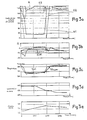
- FIGS. 3a to 3e we see the evolution of different parameters over time, in the case of the operation of a nuclear reactor on which a rapid decrease in power is achieved, at 5% per minute, from 100% up to 50% of the nominal power, then a stabilization of the power at 50% of the nominal power for one hour and finally a rapid resumption of charge at 5% per minute with stabilization at 100% of the nominal power.
- FIG. 3a the displacements of the groups of control rods have been represented in a diagram giving the number of steps extracted from the absorbent groups as a function of time.
- FIG. 3a shows the operating band of group R at the top of the heart.
- FIG. 3b shows the evolution of the axial power imbalance with respect to the reference axial imbalance and with respect to a band of width more or less 5% around the reference ⁇ I.
- the evolution of the average temperature of the core is represented compared to the evolution of the reference temperature which is a function of the power level of the reactor.
- figure 3d we have represented the evolution of the boron concentration and in figure 3e the concentration of xenon, as a function of time.
- the gray groups G1, G2, G3 are successively inserted into the reactor core to a position determined by the value of the power demanded.
- the relatively low efficiency of the light gray groups in anti-reactivity leads to a displacement of the group R in insertion beyond the neutral zone.
- the axial power imbalance ⁇ I decreases sharply to take a value less than ⁇ I ref -%.
- the width of the group R maneuvering band is then 10 steps.
- the group regulation R moves in insertion or extraction, in the same direction as the gray groups, until the reference temperature stabilizes at its new level.
- the the regulating group then returns to its operating strip by the reverse movement.
- the operating point whose coordinates correspond to the position of the group R and to the axial power imbalance is caused to move either in the borication zone or in the dilution zone. If borication or an effective dilution were then carried out, this action would in most cases go in a direction aggravating the reactivity effect resulting from the variation in the concentration of xenon which accompanies the variation in reactivity.
- a transient operating phase is rapid if the difference between the requested position and the measured position of the gray groups exceeds a certain threshold. If this threshold is exceeded, a signal controls the blocking of borication and dilution.
- the gray groups have arrived at the requested position, for example the insertion position shown in FIG. 3a, the group R has not yet returned to its operating band. The position of the operating point would then command borication in the operating case shown in FIGS. 3a to 3e. This action is not desirable since group R continues its extraction to return to its operating band, the gray bars being stationary and the power at its new level.
- a second blocking of the borication system is therefore introduced, which is activated by a signal sent when the regulating group R moves towards the neutral zone. This blocking is also maintained for the thirty seconds following the stopping of the regulation group R even if this group has not yet joined the neutral zone.
- borication or dilution
- the action of borication is blocked if the group R moves quickly, which is the case for a phase of operation in rapid transient.
- the action of borication (or dilution) is authorized if the time interval between two steps of movement of the regulation group R is greater than thirty seconds. Indeed, in this case, it is considered that the new equilibrium of the group R has been reached and a borication (or dilution) action is triggered to bring the regulation group back to the neutral zone.
- the regulation group R continues to move in the direction of extraction until it reaches the upper limit of the neutral zone.
- the extraction of the gray groups at the end of the power plateau leads to a rise in the reference temperature and a decrease in the axial power imbalance which returns to the value of the axial reference imbalance.
- the operating point then arrives in zone D1 of the diagram, which causes a modulation of the dilution rate as a function of the deviation of the operating point from the upper limit of the neutral zone.
- the injection rate is then reduced since the operating point is close to the limit of the neutral zone.
- Figure 3e shows that the concentration of xenon remained relatively stable throughout the transient.
- the main advantages of the process according to the invention are that it makes it possible to carry out all the dilution and borication operations fully automatically, taking into account the position and movements of the regulating group R and the value of the axial power imbalance.
- the temperature regulation is carried out automatically by the displacement of the group R assisted by the means of borication and dilution.
- the evolution of xenon is also perfectly controlled even in fast transients.
- the automatic control allows an early action of the borification or dilution means, independently of any movement of the temperature regulation group.
- the method according to the invention applies not only in the case of a driving mode using light gray groups in anti-reactivity and a very absorbent regulation group, called mode G, but also in the case where only heavily used groups are used absorbents, for example in the driving mode called mode A.
- the definition of the limits of the neutral zone, the dilution zone and the borication zone depends on the operating conditions of the reactor and the accepted safety standards. The numerical values given in the examples are therefore in no way limiting. The limits of the borication and dilution domains can be easily deduced from the operating trapezium of the reactor defining the operating limits of the latter.
- the dilution and borication means can be controlled so as to act in advance, by adding to the position signal of the temperature regulation group a signal proportional to the difference between the average core temperature and the reference temperature. In certain cases, however, the signal corresponding to the actual position of group R will always be used. This will always be the case, in particular when the reactor is operating in remote control or for frequency adjustment.
- the automatic control of the borication means and of the dilution means can be carried out by any means known to those skilled in the art making it possible to compare signals with predetermined values defining operating ranges of the borication or dilution means. It will be possible to visualize the position of the operating point relative to the neutral zone and to the borication and dilution zones.
- the invention applies in all cases where a pressurized water nuclear reactor uses a temperature control group consisting of bars of absorbent material and a modification of the soluble boron content of the pressurized water, for operating the reactor.
Landscapes
- Physics & Mathematics (AREA)
- Engineering & Computer Science (AREA)
- Plasma & Fusion (AREA)
- General Engineering & Computer Science (AREA)
- High Energy & Nuclear Physics (AREA)
- Chemical & Material Sciences (AREA)
- Chemical Kinetics & Catalysis (AREA)
- Monitoring And Testing Of Nuclear Reactors (AREA)
- Pharmaceuticals Containing Other Organic And Inorganic Compounds (AREA)
- Control Of Non-Electrical Variables (AREA)
Applications Claiming Priority (2)
| Application Number | Priority Date | Filing Date | Title |
|---|---|---|---|
| FR8306545 | 1983-04-21 | ||
| FR8306545A FR2544907B1 (fr) | 1983-04-21 | 1983-04-21 | Procede de reglage automatique de la teneur en bore soluble de l'eau de refroidissement d'un reacteur nucleaire a eau sous pression |
Publications (2)
| Publication Number | Publication Date |
|---|---|
| EP0127498A1 EP0127498A1 (fr) | 1984-12-05 |
| EP0127498B1 true EP0127498B1 (fr) | 1987-01-21 |
Family
ID=9288079
Family Applications (1)
| Application Number | Title | Priority Date | Filing Date |
|---|---|---|---|
| EP84400812A Expired EP0127498B1 (fr) | 1983-04-21 | 1984-04-20 | Procédé de réglage automatique de la teneur en bore soluble de l'eau de refroidissement d'un réacteur nucléaire à eau sous pression |
Country Status (8)
| Country | Link |
|---|---|
| US (1) | US4844856A (es) |
| EP (1) | EP0127498B1 (es) |
| JP (1) | JPS59208491A (es) |
| KR (1) | KR910000920B1 (es) |
| DE (1) | DE3462194D1 (es) |
| ES (1) | ES530984A0 (es) |
| FR (1) | FR2544907B1 (es) |
| ZA (1) | ZA841805B (es) |
Families Citing this family (10)
| Publication number | Priority date | Publication date | Assignee | Title |
|---|---|---|---|---|
| FR2901401A1 (fr) * | 2006-05-22 | 2007-11-23 | Areva Np Sas | Methode de regulation de parametres de fonctionnement du coeur d'un reacteur nucleaire a eau sous pression |
| KR101146950B1 (ko) * | 2010-10-15 | 2012-05-23 | 한국수력원자력 주식회사 | 원자로 붕소농도 자동제어장치 |
| FR2972839B1 (fr) * | 2011-03-15 | 2013-03-29 | Areva Np | Procede d'optimisation du pilotage d'un reacteur nucleaire a eau pressurisee lors d'un suivi de charge |
| US8699653B2 (en) * | 2011-10-24 | 2014-04-15 | Westinghouse Electric Company, Llc | Method of achieving automatic axial power distribution control |
| JP6412099B2 (ja) | 2013-03-15 | 2018-10-24 | セラダイン,インコーポレイティド | 原子炉を冷却する方法及び、多面体水素化ホウ素アニオン又はカルボランアニオンを含む原子炉 |
| WO2015079075A1 (es) | 2013-11-26 | 2015-06-04 | Ingenieria Y Marketing, S.A. | Equipo portátil de boración de aguas en flujo continuo |
| CA2946854A1 (en) | 2014-04-25 | 2015-10-29 | Ceradyne, Inc. | Pool including aqueous solution of polyhedral boron hydride anions or carborane anions and methods of using the same |
| WO2019164584A2 (en) * | 2017-12-29 | 2019-08-29 | Nuscale Power, Llc | Controlling a nuclear reaction |
| KR102160064B1 (ko) * | 2018-09-06 | 2020-09-25 | 한국수력원자력 주식회사 | 붕소농도 조절을 포함하는 부하추종운전시스템 및 이를 이용한 부하추종운전방법 |
| EP4415001A1 (en) | 2021-10-05 | 2024-08-14 | Ingeniería Y Marketing, S.A. | Portable device for the boration of continuously flowing water |
Family Cites Families (12)
| Publication number | Priority date | Publication date | Assignee | Title |
|---|---|---|---|---|
| US3380889A (en) * | 1966-03-30 | 1968-04-30 | Westinghouse Electric Corp | Boric acid removal process and apparatus |
| US3551289A (en) * | 1968-01-24 | 1970-12-29 | Westinghouse Electric Corp | Nuclear reactor |
| BE755919A (fr) * | 1969-09-27 | 1971-02-15 | Siemens Ag | Dispositif de regulation pour reacteur nucleaire a eau sous pression |
| US3998693A (en) * | 1970-11-23 | 1976-12-21 | Combustion Engineering, Inc. | Thermal margin control |
| DE2337354C3 (de) * | 1973-07-23 | 1981-06-25 | Siemens AG, 1000 Berlin und 8000 München | Vorrichtung zur Regelung eines Druckwasserreaktors mit verstellbaren Steuerstäben |
| US4057463A (en) * | 1974-08-29 | 1977-11-08 | Westinghouse Electric Corporation | Method of operating a nuclear reactor which maintains a substantially constant axial power distribution profile with changes in load |
| US4129475A (en) * | 1975-07-31 | 1978-12-12 | Westinghouse Electric Corp. | Method of operating a nuclear reactor |
| US4075059A (en) * | 1976-04-28 | 1978-02-21 | Combustion Engineering, Inc. | Reactor power reduction system and method |
| US4222822A (en) * | 1977-01-19 | 1980-09-16 | Westinghouse Electric Corp. | Method for operating a nuclear reactor to accommodate load follow while maintaining a substantially constant axial power distribution |
| FR2395572A1 (fr) * | 1977-06-23 | 1979-01-19 | Framatome Sa | Procede de controle des effets de reactivite dus aux variations de puissance dans les reacteurs nucleaires a eau pressurisee |
| FR2438320A1 (fr) * | 1978-10-05 | 1980-04-30 | Framatome Sa | Procede de conduite d'un reacteur nucleaire refroidi a l'eau legere |
| FR2493582A1 (fr) * | 1980-11-03 | 1982-05-07 | Framatome Sa | Procede de conduite d'un reacteur nucleaire par deplacement, dans le coeur de ce reacteur, de groupes de barres de commande |
-
1983
- 1983-04-21 FR FR8306545A patent/FR2544907B1/fr not_active Expired
-
1984
- 1984-03-12 ZA ZA841805A patent/ZA841805B/xx unknown
- 1984-03-15 US US06/589,788 patent/US4844856A/en not_active Expired - Lifetime
- 1984-03-26 ES ES530984A patent/ES530984A0/es active Granted
- 1984-04-20 DE DE8484400812T patent/DE3462194D1/de not_active Expired
- 1984-04-20 EP EP84400812A patent/EP0127498B1/fr not_active Expired
- 1984-04-20 JP JP59081008A patent/JPS59208491A/ja active Granted
- 1984-04-20 KR KR1019840002086A patent/KR910000920B1/ko not_active IP Right Cessation
Also Published As
| Publication number | Publication date |
|---|---|
| FR2544907B1 (fr) | 1985-07-19 |
| KR910000920B1 (ko) | 1991-02-18 |
| ZA841805B (en) | 1984-10-31 |
| JPS59208491A (ja) | 1984-11-26 |
| DE3462194D1 (en) | 1987-02-26 |
| US4844856A (en) | 1989-07-04 |
| EP0127498A1 (fr) | 1984-12-05 |
| ES8504402A1 (es) | 1985-04-01 |
| JPH0412436B2 (es) | 1992-03-04 |
| ES530984A0 (es) | 1985-04-01 |
| FR2544907A1 (fr) | 1984-10-26 |
| KR840008508A (ko) | 1984-12-15 |
Similar Documents
| Publication | Publication Date | Title |
|---|---|---|
| EP0127498B1 (fr) | Procédé de réglage automatique de la teneur en bore soluble de l'eau de refroidissement d'un réacteur nucléaire à eau sous pression | |
| EP1860664B1 (fr) | Méthode de régulation de paramétres de fonctionnement du coeur d'un réacteur nucléaire à eau sous pression. | |
| CA1097441A (en) | Method for operating a nuclear reactor to accommodate load follow while maintaining a substantially constant axial power distribution | |
| CA1094233A (fr) | Procede de controle des effets de reactivite dus aux variations de puissance dans les reacteurs nucleaires a eau pressurisee | |
| EP2686851B1 (fr) | Procede de pilotage d'un reacteur nucleaire a eau pressurisee lors d'un suivi de charge | |
| FR3002073A1 (fr) | Dispositif d'injection de securite a multiples niveaux et systeme d'injection de securite passif comportant ce dispositif | |
| FR3077412A1 (fr) | Procede de regulation de parametres operatoires d'un reacteur nucleaire et reacteur nucleaire correspondant | |
| EP2798642B1 (fr) | Procede de pilotage d'un reacteur nucleaire a eau pressurisee | |
| EP0336338B1 (fr) | Procédé de détermination et d'évaluation de la capacité de retour en puissance d'un réacteur nucléaire à eau pressurisée | |
| EP0010036A1 (fr) | Procédé de conduite d'un réacteur nucléaire refroidi à l'eau légère | |
| EP0094884B1 (fr) | Procédé et dispositif de réglage du pH de l'eau de refroidissement d'un réacteur nucléaire à eau sous pression | |
| EP1269482A1 (fr) | Procede d'incineration d'elements chimiques transuraniens et reacteur nucleaire mettant en oeuvre ce procede | |
| EP3234949B1 (fr) | Procédé de gestion de l'arrêt d'un réacteur nucléaire à eau pressurisée | |
| EP0277594B1 (fr) | Procédé de détermination du seuil d'alarme du rapport d'échauffement critique et dispositif de mise en oeuvre de ce procédé. | |
| EP0281805B1 (fr) | Procédé de détection de la chûte d'un élément antiréactif dans le réacteur d'une centrale nucléaire et centrale protégée contre une telle chûte | |
| FR3120734A1 (fr) | Procédé et système de pilotage d’une centrale nucléaire | |
| EP0128834A1 (fr) | Procédé de pilotage d'un réacteur nucléaire | |
| EP0040160B1 (fr) | Procédé de régulation de la pression du circuit primaire pendant les phases de mise à l'arrêt d'un réacteur nucléaire à eau sous pression | |
| JP2559377B2 (ja) | 蒸気発生プラントの制御装置 | |
| FR3122030A1 (fr) | Procédé et ensemble de pilotage d’un réacteur nucléaire, réacteur nucléaire équipé d’un tel ensemble | |
| EP0802410A1 (fr) | Procédé de mesure de la concentration en lithium de l'eau de refroidissement d'un réacteur nucléaire | |
| FR2467467A1 (fr) | Procede de reglage primaire de la frequence electrique delivree par une centrale nucleaire a eau legere | |
| WO2015001102A1 (fr) | Procede de pilotage en prolongation de cycle d'un reacteur nucleaire a eau pressurisee | |
| JP2553152B2 (ja) | 原子炉制御棒の自動制御方法 | |
| JPH08136693A (ja) | 原子炉の加熱装置 |
Legal Events
| Date | Code | Title | Description |
|---|---|---|---|
| PUAI | Public reference made under article 153(3) epc to a published international application that has entered the european phase |
Free format text: ORIGINAL CODE: 0009012 |
|
| AK | Designated contracting states |
Designated state(s): BE DE GB SE |
|
| 17P | Request for examination filed |
Effective date: 19841217 |
|
| 17Q | First examination report despatched |
Effective date: 19860402 |
|
| GRAA | (expected) grant |
Free format text: ORIGINAL CODE: 0009210 |
|
| AK | Designated contracting states |
Kind code of ref document: B1 Designated state(s): BE DE GB SE |
|
| REF | Corresponds to: |
Ref document number: 3462194 Country of ref document: DE Date of ref document: 19870226 |
|
| PLBE | No opposition filed within time limit |
Free format text: ORIGINAL CODE: 0009261 |
|
| STAA | Information on the status of an ep patent application or granted ep patent |
Free format text: STATUS: NO OPPOSITION FILED WITHIN TIME LIMIT |
|
| 26N | No opposition filed | ||
| EAL | Se: european patent in force in sweden |
Ref document number: 84400812.8 |
|
| REG | Reference to a national code |
Ref country code: GB Ref legal event code: IF02 |
|
| PGFP | Annual fee paid to national office [announced via postgrant information from national office to epo] |
Ref country code: GB Payment date: 20030416 Year of fee payment: 20 |
|
| PGFP | Annual fee paid to national office [announced via postgrant information from national office to epo] |
Ref country code: SE Payment date: 20030422 Year of fee payment: 20 |
|
| PGFP | Annual fee paid to national office [announced via postgrant information from national office to epo] |
Ref country code: DE Payment date: 20030430 Year of fee payment: 20 |
|
| PGFP | Annual fee paid to national office [announced via postgrant information from national office to epo] |
Ref country code: BE Payment date: 20030514 Year of fee payment: 20 |
|
| PG25 | Lapsed in a contracting state [announced via postgrant information from national office to epo] |
Ref country code: GB Free format text: LAPSE BECAUSE OF EXPIRATION OF PROTECTION Effective date: 20040419 |
|
| BE20 | Be: patent expired |
Owner name: *FRAMATOME ET CIE Effective date: 20040420 |
|
| REG | Reference to a national code |
Ref country code: GB Ref legal event code: PE20 |
|
| EUG | Se: european patent has lapsed |